Page is loading ...

2
D
F
GB
I
E
Sicherheitshinweise
☺ Prüfen Sie vor jedem Start den festen Sitz des Motors und der Luftschraube - insbesondere nach dem Transport, härteren
Landungen sowie Abstürzen. Prüfen Sie ebenfalls vor jedem Start den festen Sitz und die richtige Position der Tragflächen auf
dem Rumpf.
☺ Akku erst einstecken, wenn Ihr Sender eingeschaltet ist und Sie sicher sind, daß das Bedienelement für die Motorsteuerung auf
"AUS" steht.
☺ Im startbereiten Zustand nicht in den Bereich der Luftschraube greifen.
Vorsicht in der Luftschraubendrehebene - auch Zuschauer zur Seite bitten!
☺ Zwischen den Flügen die Motortemperatur durch vorsichtige Fingerprobe prüfen und
vor einem Neustart den Motor ausreichend abkühlen lassen. Die Temperatur ist richtig, wenn Sie den Motor problemlos berühren
können. Insbesondere bei hohen Außentemperaturen kann dieses bis zu 15 Minuten dauern.
☺ Denken Sie immer daran: Niemals auf Personen und Tiere zufliegen.
Conseils de sécurité
☺ Avant chaque décollage, vérifiez la fixation du moteur et de l'hélice, notamment après le transport, après les atterrissages
violents et après un “Crash”. Vérifiez également, avant chaque décollage la fixation ainsi que le positionnement de l’aile par
rapport au fuselage.
☺ Ne branchez l’accu de propulsion que si vous êtes sûr que votre émetteur est allumé et que l’élément de commande moteur est
en position “ARRET”.
☺ Ne mettez pas vos doigts dans l’hélice! Attention à la mise en marche, demandez également aux spectateurs de reculer.
☺ Entre deux vols, vérifiez en posant un doigt dessus, la température du moteur, laissezle refroidir suffisamment avant le prochain
décollage. La température est correcte si vous pouvez maintenir votre doigt ou votre main sur le moteur. Le temps de refroidissement
peut varier jusqu’à 15 minutes s’il fait particulièrement chaud.
☺ Pensez-y toujours: ne volez jamais vers ou au-dessus des personnes ou des animaux.
Safety notes
☺ Before every flight check that the motor and propeller are in place and secure - especially after transporting the model, and after
hard landings and crashes. Check also that the wing is correctly located and firmly secured on the fuselage before each flight.
☺ Don’t plug in the battery until you have switched on the transmitter, and you are sure that the motor control on the transmitter is set
to “OFF”.
☺ When the model is switched on, ready to fly, take care not to touch the propeller. Keep well clear of the propeller disc too, and ask
spectators to stay back.
☺ Allow the motor to cool down after each flight. You can check this by carefully touching the motor case with your finger. The
temperature is correct when you can hold your finger on the case without any problem. On hot days this may take up to 15
minutes.
☺ Please keep in mind at all times: don’t fly towards people or animals.
Note di sicurezza
☺ Prima di ogni decollo controllare che il motore e la eliche siano fissati stabilmente - specialmente dopo il trasporto, atterraggi duri
e se il modello è precipitato. Controllare prima del decollo anche il fissaggio e la posizione corretta delle ali sulla fusoliera.
☺ Collegare la batteria solo quando la radio è inserita ed il comando del motore è sicuramente in posizione ”SPENTO”.
☺ Prima del decollo non avvicinarsi al campo di rotazione della eliche. Attenzione alla eliche in movimento - pregare che eventuali
spettatori si portino alla dovuta distanza di sicurezza!
☺ Tra un volo e l’altro controllare cautamente con le dita la temperatura del motore e farli raffreddare sufficientemente prima di ogni
nuovo decollo. La temperatura è giusta se si possono toccare senza problemi. Specialmente con una temperatura esterna alta
questo può durare fino a 15 minuti.
☺ Fare attenzione: Non volare mai nella direzione di persone ed animali.
Advertencias de seguridad
☺ Compruebe antes de cada despegue que el motor y la hélice estén fuertemente sujetados, sobretodo después de haberlo
transportado, de aterrizajes más fuertes así como después de una caída. Compruebe igualmente antes de cada despegue que
las alas estén bien sujetas y bien colocadas en el fuselaje.
☺ Conectar la batería, cuando la emisora esté encendida y Usted esté seguro que el elemento de mando para el motor esté en
”OFF”.
☺ No meter la mano en la zona inmediata a la hélice cuando el avión esté a punto de despegar. ¡Cuidado con la zona de la hélice!
¡Pedir a los espectadores que se aparten!
☺ Entre los vuelos hay que comprobar cuidadosamente la temperatura del motor con el dedo y dejar que el motor se enfríe antes
de volver a despegar. La temperatura es correcta, si puede tocar el motor sin problemas. Sobretodo en el caso de temperaturas
del ambiente muy altas, esto puede tardar unos 15 minutos.
☺ Recuerde: No volar nunca hacía personas o animales.

23
GB
# 21 4193
Examine your kit carefully!
MULTIPLEX model kits are subject to constant quality checks throughout the production process, and we sincerely hope that you
are completely satisfied with the contents of your kit. However, we would ask you to check all the parts before you start construction,
as we cannot exchange components which you have already worked on. If you find any part is not acceptable for any
reason, we will readily correct or exchange it. Just send the component to our Model Department. Please be sure to include the
purchase receipt and a brief description of the fault.
We are constantly working on improving our models, and for this reason we must reserve the right to change the kit contents in
terms of shape or dimensions of parts, technology, materials and fittings, without prior notification. Please understand that we
cannot entertain claims against us if the kit contents do not agree in every respect with the instructions and the illustrations.
Caution!
Radio-controlled models, and especially model aircraft, are by no means playthings. Building and operating them safely
requires a certain level of technical competence and manual skill, together with discipline and a responsible attitude at
the flying field. Errors and carelessness in building and flying the model can result in serious personal injury and
damage to property. Since we, as manufacturers, have no control over the construction, maintenance and operation of
our products, we are obliged to take this opportunity to point out these hazards and to emphasise your personal
responsibility.
Additional items required:
For the electric and glow powered models:
Receiving system (in the model)
MULTIPLEX Micro IPD receiver 35 MHz A-band Order No. 5 5971
alternatively: 40 MHz band Order No. 5 5972
or MULTIPLEX RX-9 Synth DS IPD receiver 35 MHz A-band Order No. 5 5890
MULTIPLEX Mini HD servo, 3 x (4 x for glow version)
Elevator / Rudder / Aileron / Throttle Order No. 6 5123
Additional items for the electric version:
Power set:
MULTIPLEX 680G electric power set Order No. 33 2668
Permax 680/8.4 V, 3:1 gearbox (600 DP), propeller adaptor, spinner and propeller
Speed controller:
MULTIPLEX PiCO-Control 400 Duo Speed controller Order No. 7 5024
Flight battery:
MULTIPLEX Permabatt NiMH flight pack 8/3000 mAh Order No. 15 6027
Additional items for the glow version:
MULTIPLEX Permabatt NiMH receiver battery 4/1500 mAh Order No. 15 6007
MULTIPLEX switch harness with charge socket, black Order No. 8 5039
Two-stroke motor, approx. 5 cc (.25 - .36 cu. in.)
or
Four-stroke motor, approx. 6.5 cc (.26 - .30), weight no greater than approx. 300 g!
Propeller, spinner, fueltank, electric starter, fuel and glowplugs.
Adhesives: cyano-acrylate (“cyano”) and activator; 5-minute epoxy
Use medium-viscosity cyano glue (not styrofoam cyano). It is important to use activator when using cyano. Epoxy adhesives
produce what initially appears to be a sound joint, but the bond is only superficial, and the hard resin breaks away from the parts
under load.
Tools:
Scissors, balsa knife, combination pliers, 2.5 and 4 mm Ø twist drills, cross-point screwdriver, small round file.
Specification:
Wingspan 1630 mm
Fuselage length 1170 mm
All-up weight, electric 680 motor / 8 x SC cells approx. 2380 g
All-up weight, glow approx. 5 cc motor approx. 1950 g
Wing area approx. 45 dm²
Wing loading (FAI) approx. 53 g/ dm²
RC functions Aileron, elevator, rudder and motor; optional aero-tow release
Note: please remove the illustration pages from the centre of the instructions.

24
Important note
This model is not made of styrofoam™, and it is not
possible to glue the material using white glue or epoxy.
Please be sure to use cyano-acrylate glue exclusively,
preferably in conjunction with cyano activator (kicker). We
recommend medium-viscosity cyano. This is the
procedure: spray cyano activator on one face of the
Elapor®; allow it to air-dry, then apply cyano adhesive to
the other face. Join the parts, immediately position them
accurately, and wait a few seconds for the glue to harden.
Please take care when handling cyano-acrylate adhesives.
These materials harden in seconds, so don’t get them on
your fingers or other parts of the body. We strongly
recommend the use of goggles to protect your eyes. Keep
the adhesive out of the reach of children.
1. Before assembling the model
Check the contents of your kit.
You will find Figs. 1 + 2 + 3 and the Parts List helpful here.
Note: the Parts List states the correct length of the control
“snakes”, but they are supplied oversized. You will therefore
find the following lengths in the kit:
2 off 3/2 Ø x 825 mm snake outer sleeve
1 off 3/2 Ø x 750 mm snake outer sleeve
2 off 2/1 Ø x 820 mm snake inner tube
1 off 2/1 Ø x 600 mm snake inner tube
Electric or glow version?
The Magister kit can be assembled either as an electric-
powered model or a glow-powered version. The parts which
differ in the two versions are the cowl, the fuselage nose, the
motor mount and various internal parts such as fueltank and
speed controller. The building instructions describe in parallel
how to make both versions - text and pictures which are not
specifically marked apply to both versions.
The texts and pictures marked “GP” apply to the glow version
only.
If you are a newcomer to model flying and have no experience
handling internal combustion engines, we recommend that you
complete the model with an electric power system. Compared
with a glowplug motor an electric power system has the great
advantage of excellent reliability and simple maintenance: just
charge the batteries, and away you go.
2. Preparing the control “snakes”
The snake outer and inner tubes should first be cut to the lengths
stated in the next column. This is done by placing the tubes on
a hard surface and notching them all round using a balsa knife
(roll it tube to and fro under the blade), after which the excess
can simply be broken off. Write the purpose of tube on a scrap
of masking tape and stick the tape to the tubes.
3/2 mm Ø snake outer sleeves
825 mm: 53 575 mm and 54 250 mm
825 mm: 51 408 mm and 51 408 mm
750 mm: 52 440 mm and 55 305 mm
2/1 mm Ø snake outer sleeves
820 mm: 57 460 mm and 59 350 mm
820 mm: 56 408 mm and 56 408 mm
600 mm: 58 600 mm
The short pieces left over are not required for the model.
Fig. 3
Permax 680/8.4 V geared motor # 33 2671
For the electric version we recommend this geared motor.
Assemble the gearbox as described in the instructions supplied
with it. Use the propeller and spinner supplied in the set.
Attach the gearbox housing to the electric motor bulkhead 43
using three screws (included in the power set). Fix the two motor
mounts 41 to the motor bulkhead using the screws 34. Note
the installed position of the motor!
Fig. 04
Fix the motor mounts 41 to the firewall 42 using the screws 34.
Fig. 05
Attach the bulkhead braces 40 to the firewall 42 using the screws
34.
Fig. 08
Preparing the motor mount
GP:
Attach the two motor mounts 41 to the motor using two screws
34 on each side. You will need to drill 2.5 mm Ø holes
beforehand to accept the screws.
Position the motor on the two motor mounts so that there is
about 5 mm clearance to the fuselage nose when the spinner
is fitted.
Fig. 06 GP
GP:
Fix the motor mounts 41 to the firewall 42 using the screws 34.
Fig. 07 GP
Preparing the wing and tailplane retainer plates
Roughen the joint surfaces of the hank nuts 33 using coarse
abrasive paper and glue them in the holes in the tailplane
retainer plate 82 using 5-minute epoxy.
Fig. 09
Press the captive nuts 32 into the wing retainer plate 80 and
secure them with 5-minute epoxy.
Fig. 10
Preparing the main undercarriage mount
Glue the channeled undercarriage rail 83 and the two support
blocks 84 to the retainer plate 81 using 5-minute epoxy, cyano
or white glue. Hold the parts together using screw-clamps or a
vice until the glue has set hard.
Fig. 11
Mark a point 12.5 mm from each end of the channel in the rail
83. Drill two 4 mm Ø holes at right-angles through the rail
channel and the two support blocks 84, one at the front of the
channel, one at the rear.
Figs. 12 + 13
Check that the undercarriage legs 61 fit correctly, and round
off the edges of the holes in the channeled rail to allow for the
radius of the bends. It should be possible to press the two legs
into the channel full-depth, so that they lie flush at the top.
Preparing the fuselage
If you are making the electric version, open up the cooling slots
in the left and right fuselage shells 3 and 4. This is easiest with
a sharp balsa knife and a small round file.
Fig. 14:
GP:
The glow fuselage nose 7 has to be cut away along the recessed
lines to clear your motor. Use a sharp balsa knife for this, and

25
trim the opening to fit neatly round the motor. It may be
necessary to extend the opening right to the front, depending
on the motor you are using. Don’t leave any very small areas
projecting, as they will just break off.
Fig. 15 GP
Installing the aero-tow release
Apply activator to the fuselage insert 5 and glue the aero-tow
mechanism 76 in the channel in the insert.
Fig. 16
If you intend to use the aero-tow release at any time, it is
important not to allow glue to get on the fuselage insert 5 when
gluing the fuselage shells together. To install the aero-tow servo
at a later stage, slice through the side lugs of the fuselage insert
using a balsa knife, and pull the insert up and out.
To operate the aero-tow release you will need one additional
servo. The servo can be installed at this stage or at any later
time.
Connect the tow release pushrod (e.g. 1 mm Ø spring steel
wire with one Z-bend) to the innermost hole in the servo output
arm and slide the servo into the recess in the fuselage insert.
Set the servo output arm to the “towline locked” end-point and
cut off the projecting pushrod at a point just above the tow
mechanism. Carefully round off the cut end with abrasive paper
to avoid it snagging the towline.
Place or glue the fuselage insert 5 in the left-hand fuselage
shell 3.
Fig. 17
Preparing the noseleg snake
Slip the steel pushrod 70 for the steerable noseleg into the
snake outer sleeve 55 and solder the threaded coupler 71 to
the plain end; be sure to sand the end of the rod thoroughly
before soldering. Alternatively the coupler can be glued to the
end using UHU Plus Endfest 300 (slow-setting epoxy). In this
case allow the epoxy to cure overnight.
Fig. 18
Fit the pushrod assembly in the channel in the fuselage shell 4
running to the rudder servo recess, Z-bend first. Set the snake
outer 55 projecting by about 15 mm and glue it to the fuselage
shell, applying 5-minute epoxy inside and out.
Fig. 19
Assembling the fuselage
Apply activator to the joint surface of the right-hand fuselage
shell 4 where it meets the fuselage nose 6 / 7GP and allow it to
air-dry. Apply cyano to the joint surface of the fuselage nose 6
/ 7 GP and glue it to the fuselage shell 4.
Temporarily place the prepared motor mount assembly in the
left-hand fuselage shell 3 and check that it is a snug fit. Do the
same with the retainer plates for the undercarriage, wing and
tailplane.
When you are confident that everything fits properly glue these
assemblies in the left-hand fuselage shell one by one.
Caution: important!
The left and right fuselage shells can now be offered up to
each other, so that you can check that they mate together fully:
ensure that the various components fit exactly in the appropriate
recess in the opposite shell; if not, trim the right-hand shell
until they do.
Once you are sure that everything fits properly, apply activator
to the joint surfaces of the left-hand fuselage shell 3.
Apply cyano to the joint areas of the right-hand fuselage shell -
including the plastic motor mount parts - this is very important.
The joints between the wooden parts and the fuselage
mouldings can be reinforced later from the outside, as they are
mechanically locked in place anyway. It is essential to work
quickly when joining the fuselage shells - a second pair of hands
is a great help at this stage. Fit the two fuselage shells together
and ensure that the projecting plates fit correctly in the recesses
on the opposite side. Press the fuselage shells together
completely and ensure that the fuselage joint line is straight,
as this ensures a true fuselage.
Fig. 20
Assembling the noseleg unit
Fit a grubscrew 66 into each of the collets 64 (4.2 mm I.D.)
using the allen key 29.
Secure the nosewheel 63 on the noseleg unit 60 by placing a
collet on each side of it. Check that the wheel has sufficient
clearance to rotate freely, then tighten the grubscrews.
Fig. 21
Press the steering arm insert 67 into the steering arm 77,
cylindrical face first, and secure it with two grubscrews 66.
Fig. 22
The noseleg assembly can now be fitted into the integral bush
in the motor bulkhead from the underside. Fit the collet 64
between the top brackets, followed by the steering arm 77. Set
the noseleg flush with the top bracket, then tighten the collet
against the bottom bracket. Set the steering arm at right-angles
(90° to the direction of flight), resting against the top bracket.
Adjust the nosewheel to the “straight ahead” position, then
tighten the grubscrews.
Connect the clevis to the outermost hole in the steering arm.
Glue the snake outer to the projecting lug of the bulkhead brace
40 using 5-minute epoxy.
Fig. 23
Assembling the main undercarriage
Locate the two collets 65 (5.1 mm I.D.) with an additional 1 mm
Ø hole and fit a grubscrew 66 in each using the allen key 29.
Insert the pre-formed damper wire 62 in the extra hole and fix
it to the main undercarriage unit 61 using the collet 65. Repeat
the procedure with the second main undercarriage leg.
Fit the wheels 63 on the legs and secure each with a collet 64.
Fig. 24
Place the undercarriage retainer strap 78 over the channeled
rail 83 in the fuselage recess, with the hooked slot at the rear,
and mark the position of the holes using the retainer strap as a
guide. Drill 1.5 mm Ø holes at the marked points.
Insert the main undercarriage legs in the holes in the channeled
rail 83; the undercarriage legs should now rest snugly side by
side in the channel. Fix the undercarriage retainer strap 78 to
the fuselage using the four screws 68.
Fig. 25
Connect the rubber band 69 to the hook on the undercarriage
retainer strap 78, run it around the damper wire 62 and connect
it to the hook again. The rubber band significantly reduces the
model’s tendency to bounce on landing.
Fig. 26
GP:
Preparing the throttle linkage for the glow motor
Solder the M2 threaded coupler 73 to the steel throttle pushrod
49.
Screw the plastic clevis 36 on the coupler. Slip the steel pushrod
49 through the snake outers 54 and 59.
Fig. 27 GP

26
GP:
Installing the throttle servo and throttle pushrod for the
glow motor, connecting the linkage
Assemble a pushrod connector consisting of parts 25, 26, 27
and 28 for the throttle servo which controls the glowplug motor,
and mount the connector on the servo output arm. You will
need to drill out the output arm to 2.5 mm Ø to accept the
connector. Secure the nut on the pushrod connector with a
drop of cyano or 5-minute epoxy. Press the throttle servo into
the recess in the fuselage below the wing saddle, and secure it
with a little 5-minute epoxy applied to the top of the servo
mounting lugs.
Slip the throttle pushrod from the motor through the slot in the
firewall 42 to the pushrod connector on the throttle servo.
Connect the plastic clevis to the carburettor throttle arm, and
clamp the pushrod in the pushrod connector on the servo using
the allen key 29. The grubscrew 28 can be tightened by gripping
the allen key in a pair of pliers and passing it through the opening
in the wing mount.
Figs. 28 GP + 29 GP
GP:
Installing and connecting the fueltank
Select a suitable fueltank for the motor you intend to use, install
it in the model and connect it to the motor, referring to the
instructions provided by the motor manufacturer. It is important
to check that the tank fits in the available space in the fuselage.
When installing the fueltank note that the throttle pushrod must
run along the fuselage side to one side of the tank. You may
need to bend the pushrod slightly to clear the tank you are
installing.
Fig. 30 GP
Releasing the ailerons and rudder
The control surfaces are supplied still attached to the wing and
tailplane by means of one or two small, recessed lugs. The
particle foam itself acts as the hinge - no additional hinge tape
or similar is necessary. Remove the lugs by making two paral-
lel cuts spaced about 1 mm apart using a balsa knife. Flex the
control surfaces repeatedly up and down in order to free up the
hinge. Caution: take care not to separate the control surfaces
from the wing or tailplane at the hinge axis.
You may find that odd foam particles are missing along the
hinge line; this is of no importance, and is not grounds for
complaint.
Preparing the pushrod connectors
Fit the elevator and rudder pushrod connectors 25 in the
outermost hole of the horns 24 and secure them with the
washers 26 and nuts 27. Caution: note the correct orientation
of the connectors. Tighten the nuts carefully, ensure that the
connectors swivel smoothly, then apply a tiny drop of cyano
(on a pin) to prevent them shaking loose. Fit the socket-head
grubscrews (28) in the pushrod connectors 25 using the allen
key 29.
Figs. 31 + 3
Fit the pushrod connectors 25 in the second hole from the
outside of the aileron horns 24 and prepare them as described
above.
Caution: 1 x left, 1 x right.
Apply activator to the horn recesses in the elevator 14 and
rudder 15, and glue the prepared horns 24 in them using cyano.
Note that the row of holes must face the hinge line. Caution:
check correct horn orientation.
Figs. 31 + 33 + 38
Attaching the tail panels
Glue the fin 15 in the recess in the fuselage, taking care to set
it exactly at 90° to the wing and tailplane saddles. Check first
and trim if necessary.
Fig. 32
Glue the plastic bushes 35 in the tailplane 14, flush with the top
surface. Fix the tailplane to the fuselage using the screws 31
and check that it is correctly positioned (90° to the fin, parallel
to the wing saddle). The screws can be tightened using the
plastic combination tool 79, or any standard screwdriver.
Fig. 34
Installing the servos in the fuselage
Set the servos to neutral (centre) from the transmitter and fit
the output levers on them with the arms at 90° to the long case
sides at neutral. Temporarily fit the servos in the sides of the
fuselage; you may need to make minor adjustments to suit the
servos you are using. Pierce the tunnels for the servo leads
using a round file or bradawl, and thread the leads through into
the fuselage. Shrink pieces of heat-shrink sleeve round the
servos (or wrap tape round them), then glue them in place.
Note: don’t omit the tape or heat-shrink sleeve, otherwise the
glue may penetrate the servo case and jam the mechanism.
Fig. 35
Installing the linkages in the fuselage
The elevator and rudder linkages take the form of the snake
outer sleeves 51, the snake inner tubes 56 and the pre-formed
steel rods 46. Fit these parts together and connect the pre-
formed wire ends to the servo output arms.
Figs. 35 + 37
Connect the elevator and rudder pushrods to the servo output
arms at a lever length of around 13 mm (i.e. distance from
linkage hole to output shaft centre).
The nosewheel is steered by the rudder servo. Set the rudder
servo and nosewheel to neutral by screwing the clevis 72 in or
out.
Figs. 35 + 23
Fit the other end of the steel pushrods 46 through the cross-
holes in the pushrod connectors 25. Press the snake outers
into the channels in the fuselage. You will need to bend the
steel pushrod 46 at the rudder horn to obtain the correct angle;
use a pair of pliers for this.
Figs. 38 + 36
The snake outer sleeves 51 can now be glued to the fuselage
over their full length. Check that the snakes operate smoothly,
and take care to avoid glue getting into the outer sleeve. Finally
centre the servos and control surfaces again and tighten the
socket-head grubscrews 28 in the pushrod connectors 25.
The wing joiner system
Carefully glue the wing joiner covers 12 and 13 in the wing
panels 10 and 11, applying glue to the bottom and both sides.
Take particular care to keep the glue away from the surfaces
into which the wing joiner tube 45 will be fitted later. The next
step is to check that the joiner tube 45 fits, but not until you are
sure that there is no active adhesive inside the socket. It is a
good idea to spray activator into the opening and wait for it to
take effect. If you neglect this, you may find that the wings can
never be separated again!
Fig. 39
Preparing for installation of the aileron servo
Both ailerons are actuated by snakes from a single central servo
installed in the left-hand wing panel. This arrangement ensures

27
that a simple 4-channel radio control system can be used to
control the model. An articulated pushrod connector is mounted
on the servo output disc to provide an easy means of engaging
and disengaging the second linkage. The pushrod in the right-
hand wing is fixed permanently to the swivelling part of the
connector. The wire pushrod for the left-hand aileron is
connected to the servo output disc using a simple Z-bend. The
servo lead runs to the fuselage through the tunnel in front of
the wing joiner tube. The unsupported length of the pre-formed
pushrod presents no problems.
Mount the articulated connector housing 37 in the outermost
hole of the servo output disc using the M1.6 x 4 mm countersunk
screw 39 - see Fig. 43. Tighten the screw carefully: just to the
point where the articulated housing swivels smoothly, but does
not wobble. It is important that the housing should be free-
moving, but not sloppy. You may need to tighten the screw
slightly after the first few flights. Fit the socket-head grubscrew
28 in the articulated connector barrel 38, and snap the barrel
38 into the housing.
Figs. 40 + 43
Note: it is very easy to disconnect the pushrod connector using
a screwdriver with a blade tip approx. 4 mm wide. Simply slip
the screwdriver between the articulated connector housing and
the barrel and twist it gently - the barrel pops out, and can later
be re-fitted in exactly the same position.
Checking the wing joiner system
Plug the wing panels together using the joiner tube 45. Trim
the parts if necessary to obtain a close fit.
Fig. 41
Installing the aileron servo and snakes
The left-hand aileron linkage consists of the snake outer sleeve
52, the snake inner tube 57 and the pre-formed steel rod 47.
Fit these parts together and connect the pre-formed end to the
servo output disc adjacent to the articulated pushrod connector.
Caution: the pre-formed pushrod must be fitted between the
servo and the output disc, or it will foul the articulated connector.
Glue the aileron servo in the servo recess as described for the
rudder and elevator servos.
The right-hand aileron linkage consists of the snake outer sleeve
53, the snake inner tube 58 and the steel rod 48.
Figs. 42 + 43
Carefully curve the snake outer sleeves to follow the line of the
channels in the wings, fit them in the channels running to the
ailerons and secure them with cyano. The outer sleeve should
end short of the aileron, approximately at the end of the inte-
gral pushrod fairing, and should not be glued in place over the
last 4 cm.
The prepared aileron horns 24 - with the row of holes facing
the hinge line - can now be glued in the horn recesses in the
ailerons, after applying activator as previously described. Fit
the other ends of the steel pushrods 47 / 48 through the cross-
holes in the pushrod connectors 25. Set the servo and ailerons
to neutral (centre), adjust the pushrod lengths at the pushrod
connectors and tighten the clamping screws. Caution: check
that the two wings make full contact at the root before you tighten
the screws.
Figs. 44
Check that the joined wings can be attached to the fuselage
correctly using the screws 31 and the wing retainer straps 30.
Trim carefully if necessary. You can use the combination tool
79 supplied to tighten the screws.
Fig. 45
Trimming the cowl / canopy to fit
GP:
The glow version cowl / canopy 9 has to be cut away and
trimmed to clear the motor and carburettor. At the same time
mark the position of the needle valve and cut a clearance hole
for it. This is one area where a compromise has to be struck
between open access and smooth good looks. We recommend
that you err on the side of good access, and allow plenty of
clearance. A soldering iron is a useful tool for cutting narrow
slots.
Attaching the cowl / canopy
The electric cowl / canopy 8 is fitted by sliding it into the fuselage
from the front, towards the wing; it can then be folded down
into position at the front.
Fig. 46
Installing the canopy latches
Glue the canopy latches 22 to both sides of the front fuselage
area.
Fig. 47
Connect the latch straps 75 to the canopy latches 22 on both
sides and position the appropriate cowl / canopy (8 or 9) on the
fuselage. Fix the two latch straps 75 to the cowl / canopy using
one screw 23 each, holding them under slight tension. Check
that the latches operate reliably, then apply a little cyano to the
area of the screw head to provide extra strength where the
latch straps are screwed. To improve the appearance of the
latches the screw-heads can be coloured black using a black
waterproof felt-tip pen.
Fig. 48
Soldering the speed controller to the motor
The speed controller # 7 5024 can now be soldered to the motor
terminals. Take care to maintain correct polarity: the single-
stage gearbox reverses the direction of rotation, so the positi-
ve wire must be soldered to the negative motor terminal.
Complete the soldering as quickly as possible to avoid heat
damage, applying solder whilst the iron is in contact.
The motor is supplied with a suppressor already fitted - when
soldering the speed controller leads to the terminals make sure
that the wire ends of the capacitor are soldered in place at the
same time.
Fitting the propeller and spinner
The propeller and spinner are included in the Electric Power
Set 680G # 33 2668. Mount these parts on the motor as
described in the instructions supplied in the set.
GP:
Installing the receiver battery and switch harness
If you are building the glow version, you have to install a sepa-
rate receiver power supply consisting of a receiver battery and
a switch harness. Fix the battery in the fuselage using Velcro
tape. Check the CG position before you position the battery
permanently.
The switch can be installed inside the fuselage or on the outside,
in which case you will need to cut a suitable hole for it.
Installing the flight battery and receiver
The flight pack and receiver are installed as follows: the flight
battery should be positioned in the fuselage under the wing,
with the receiver below it. Check the CG position before you
position these items permanently. Glue the Velcro tape
(“mushroom” face) to the inside of the fuselage floor at the
flight battery / receiver location. Note that the adhesive of the

28
tape is not strong enough on its own for this application; glue
the tape in place with cyano.
The final position of the flight pack is determined when you set
the correct Centre of Gravity. It should then be marked clearly.
Ensure that the Velcro tape which holds the battery in place
makes good contact. If you neglect this, you may lose your
battery in flight.
Check before every flight that the battery is securely fixed.
Temporarily complete all the electrical connections as described
in the radio control system instructions.
Do not connect the flight battery to the speed controller
until you have switched on the transmitter and are sure
that the throttle control is at the “OFF” position.
Connect the servo plugs to the receiver. Switch the transmitter
on, then connect the flight battery in the model to the speed
controller, and the controller to the receiver. It is essential that
your speed controller is what is known as a BEC type (Battery
Eliminator Circuit - the flight pack powers the receiving system).
Switch the motor on briefly and check once more the direction
of rotation of the propeller. Remember to hold the model
securely when test-running the motor, and remove all loose,
light objects in front of and behind the model - before the
propeller removes them for you. If the propeller spins in the
wrong direction, swap over the connections at the motor
terminals - not at the flight battery!
Caution: keep well clear of the propeller when the battery
is connected - serious injury hazard!
Deploying the receiver aerial on the underside of the
fuselage
The receiver aerial should be threaded through a hole in the
underside of the fuselage, then deployed aft in the direction of
the tailplane.
This is done by piercing a tunnel through the fuselage side to
the outside, threading the aerial through it and taping it full-
length to the fuselage.
Setting the control surface travels
The control surface travels must be set correctly to ensure that
the model has harmonious, well-balanced control response:
Elevator
up (stick back) 15 mm
down (stick forward) 12 mm
Rudder
left and right each 25 mm
Ailerons (opposite directions)
up 15 mm
For a right-hand turn the right aileron (as seen from behind the
model) must deflect up. The “down” travel is not critical, and
will be correct automatically.
Always measure the control surface travels at the widest part
of the surface.
If your radio control system does not allow you to set these
precise travels, don’t worry, as they are not crucial. If the
discrepancy is large, you may have to re-position the appropriate
pushrod connector, mounting it in a different hole.
Applying the glass filament tape
The strips of glass filament tape 16 (self-adhesive glass fibre
rovings) supplied in the kit are applied to the top and bottom of
the wing panels 10 + 11. The tape should be stuck behind the
recess for the front wing retainer strap 30, extending out to the
wingtip (55 mm from the leading edge). The tape should not be
under tension. On the underside of the wing apply the tape in
the corresponding position and cut it away at the servo recess
- in this area the wing joiner bears the flight loads in any case.
Stick the filament tape in place before applying the decals.
Caution: keep the wings perfectly flat while you are applying
the tape - they should not be bent or curved! The main purpose
of the glass tape is to reduce the flexing of the wings when the
flight loads are fairly high.
Gilding the lily - applying the decals
The kit is supplied with a multi-colour decal sheet 2. Cut out
the individual name placards and emblems and apply them to
the model in the position shown in the kit box illustration, or in
an arrangement which you find pleasing. The decals adhere
strongly, so make sure they are positioned correctly first time!
Balancing
The Magister, like any other aircraft, must be balanced at a
particular point in order to achieve stable flying characteristics.
Assemble your model ready to fly, and install the flight battery.
The Centre of Gravity (CG) should be about 85 mm from
the leading edge at the root, measured at the fuselage.
Mark this point on both sides of the fuselage. Support the
model at this point on two fingertips and it should balance level.
If not, you can move the flight battery forward or aft to correct
the balance point. Once the correct position is found, mark the
location of the battery inside the model to ensure that it is always
replaced in the same position.
The CG location is not critical - 10 mm forward or aft of the
stated position presents no problems.
Fig. 49
Preparing for the first flight
For the first flight wait for a day with as little breeze as possible.
The early evening is often a good time.
Be sure to carry out a range check before the first flight.
Just before the flight, charge up the transmitter battery and the
flight pack using the recommended procedures. Ensure that
“your” channel is not already in use before you switch on the
transmitter.
Ask your assistant to walk away from the model, holding the
transmitter. The aerial should be fitted but completely collapsed.
Your assistant should operate one of the functions constantly
while you watch the servos. The non-controlled servo should
stay motionless up to a range of about 60 m, and the controlled
one should follow the stick movements smoothly and without
any delay. Please note that this check can only give reliable
results if the radio band is clear of interference, and if no other
radio control transmitters are in use - even on different channels.
If the range check is successful, repeat it with the motor running.
There should be only a very slight reduction in effective radio
range with the motor turning.
If you are not sure about anything, please don’t risk a flight.
Send the whole system (including battery, switch harness and
servos) to the service department of your RC system
manufacturer and ask them to check it.
The first flight ...
The Magister should always be launched exactly into any wind.
If you are a beginner to model flying we strongly
recommend that you ask an experienced model pilot to
help you for the first few flights.

29
Taking off from a hard strip
If you have access to a hard landing strip, a ground take-off is
the safest option.
Point the model directly into wind and open the throttle gradually
so that the aircraft accelerates. Keep the model on track using
the nosewheel / rudder. Apply full-throttle to continue
accelerating. When the model reaches flying speed apply gentle
up-elevator to lift off. Allow the model to climb at a steady, fairly
shallow angle, taking care to keep the airspeed up.
From a closely mown grass strip a ground take-off works just
like on a hard strip, but the ground-roll will be longer. If you do
not have access to a take-off strip, a hand-launch works fine.
Caution: if your assistant is an experienced hand-launcher then
you can be confident of success; if not, watch out!
Hand launching
Don’t try unpowered test-glides with this model. The Magister
should always be hand-launched with the motor running at full-
throttle, and always exactly into wind.
Ask an experienced modeller to hand-launch your model for
you: he should run forward for two or three paces, then give
the aircraft a powerful straight launch, wings and fuselage level.
Use the controls to hold the model in a steady, gentle climb -
remember to keep the rate of ascent shallow and the airspeed
high!
Allow the aeroplane to climb to a safe height, then adjust the
trim sliders on the transmitter until it flies in a perfectly straight
line “hands off”.
While the model is still at a safe altitude, switch off the motor
and try out the controls on the glide. Carry out a “dry run” landing
approach at a safe height so that you are prepared for the real
landing when the battery runs flat (or the glow motor stops).
Don’t try any tight turns at first, and especially not on the landing
approach at low altitude. It is always better to land safely at
some distance from you, than to force the model back to your
feet and risk a heavy landing.
Safety
Safety is the First Commandment when flying any model aircraft.
Third party insurance should be considered a basic essential.
If you join a model club suitable cover will usually be available
through the organisation. It is your personal responsibility to
ensure that your insurance is adequate (i.e. that its cover
includes electric / glow powered model aircraft).
Make it your job to keep your models and your radio control
system in perfect order at all times. Check the correct charging
procedure for the batteries you are using. Make use of all sen-
sible safety systems and precautions which are advised for
your system. An excellent source of practical accessories is
the MULTIPLEX main catalogue, as our products are designed
and manufactured exclusively by practising modellers for other
practising modellers.
Always fly with a responsible attitude. You may think that flying
low over other people’s heads is proof of your piloting skill;
others know better. The real expert does not need to prove
himself in such childish ways. Let other pilots know that this is
what you think too. Always fly in such a way that you do not
endanger yourself or others. Bear in mind that even the best
RC system in the world is subject to outside interference. No
matter how many years of accident-free flying you have under
your belt, you have no idea what will happen in the next minute.
We - the MULTIPLEX team - hope you have many hours of
pleasure building and flying your new model.
MULTIPLEX Modellsport GmbH & Co. KG
Product development and maintenance
Klaus Michler
Replacement parts - Magister
# 22 4187 Moulded fuselage components
# 22 4188 Moulded wing components
# 22 4189 Moulded tail components
# 72 3189 Wing joiner tube
# 72 4197 Decal sheet
# 33 2681 600P 3:1 gearbox
# 33 2670 Permax 680/8.4V motor with 15-tooth pinion
# 73 4348 12 x 8” propeller
# 45 3115 44 mm Ø spinner
Our comprehensive range of products includes dozens of small
items and other accessories suitable for this model. Please refer
to the current main catalogue or visit our web site:
www.multiplex-rc.de
Our products are supplied exclusively through specialist model
shops.

30
Part No. Description Material Dimensions
No. off
1 1 Building instructions Paper, 80 g/m² A4
2 1 Decal set Printed adhesive film 700 x 1000 mm
3 1 L.H. fuselage shell Moulded Elapor foam Ready made
4 1 R.H. fuselage shell Moulded Elapor foam Ready made
5 1 Fuselage insert, aero-tow release Moulded Elapor foam Ready made
6 1 Fuselage nose, electric version Moulded Elapor foam Ready made
7 1 Fuselage nose, glow version Moulded Elapor foam Ready made
8 1 Cowl / canopy, electric version Moulded Elapor foam Ready made
9 1 Cowl / canopy, glow version Moulded Elapor foam Ready made
10 1 L.H. wing panel Moulded Elapor foam Ready made
11 1 R.H. wing panel Moulded Elapor foam Ready made
12 1 L.H. wing joiner cover Moulded Elapor foam Ready made
13 1 R.H. wing joiner cover Moulded Elapor foam Ready made
14 1 Tailplane Moulded Elapor foam Ready made
15 1 Fin Moulded Elapor foam Ready made
16 2 Glass filament tape, pair of strips Self-adhesive glass 25 x 800 mm
Small items
20 3 Velcro tape, “mushroom” Plastic 25 x 60 mm
21 3 Velcro tape, “felt” Plastic 25 x 60 mm
22 2 Canopy latch Inj. moulded plastic Ready made
23 2 Countersunk chipboard screw Metal 5 x 25 mm
24 4 Glue-fitting control surface horn Inj. moulded plastic Ready made
25 5 Pushrod connector, 6 mm Ø Metal Ready made
26 5 Washer Metal M2
27 5 Nut Metal M2
28 6 Socket-head grubscrew Metal M3
29 1 Allen key Metal 1.5 mm A/F
30 2 Wing retainer strap Inj. moulded plastic Ready made
31 4 Screw Plastic M5 x 50 mm
32 2 Captive nut Metal M5
33 2 Hank nut Metal M5
34 12 Screw Metal 2.9 x 16 mm
35 2 Glue-fitting bush Inj. moulded plastic M5
36 1 Throttle clevis Inj. moulded plastic M2
37 1 Articulated connector housing Plastic Ready made
38 1 Articulated connector barrel, 6 Ø Metal Ready made
39 1 Countersunk machine screw Metal M1.6 x 4 mm
Motor mount, complete / glow and electric versions
40 2 Bulkhead brace Inj. moulded plastic Ready made
41 2 Motor mount Inj. moulded plastic Ready made
42 1 Firewall Inj. moulded plastic Ready made
43 1 Motor bulkhead, electric version Inj. moulded plastic Ready made
Wire and rod
45 1 Wing joiner tube GRP tube 10 Ø - 0.4 x 1 x 800 mm
46 2 Pre-formed steel pushrod, ele. / rudder Metal 0.8 Ø x 492 mm
47 1 Pre-formed steel pushrod, L.H. aileron Metal 0.8 Ø x 547 mm
48 1 Pre-formed steel pushrod, R.H. aileron Metal 0.8 Ø x 700 mm
49 1 Steel pushrod, throttle Metal 0.8 Ø x 350 mm
51 2 Snake outer sleeve, elevator / rudder Plastic 3/2 Ø x 408 mm
52 1 Snake outer sleeve, L.H. aileron Plastic 3/2 Ø x 440 mm
53 1 Snake outer sleeve, R.H. aileron Plastic 3/2 Ø x 575 mm
54 1 Snake outer sleeve, throttle Plastic 3/2 Ø x 250 mm
55 1 Snake outer sleeve, noseleg Plastic 3/2 Ø x 305 mm
56 2 Snake inner tube, elevator / rudder Plastic 2/1 Ø x 408 mm
57 1 Snake inner tube, L.H. aileron Plastic 2/1 Ø x 460 mm
58 1 Snake inner tube, R.H. aileron Plastic 2/1 Ø x 600 mm
59 1 Snake inner tube, throttle Plastic 2/1 Ø x 350 mm
# 21 4193
E

31
Part No. Description Material Dimensions
No. off
Undercarriage components
60 1 Noseleg unit Spring steel 4 Ø, ready made
61 2 Main undercarriage leg Spring steel 4 Ø, ready made
62 1 Damper wire Spring steel 1 Ø, ready made
63 3 Lightweight wheel Plastic 73 Ø, hub 4 mm
64 5 Collet Metal 4.2 / 8 Ø x 5 mm
65 2 Collet with supplementary 1 mm hole Metal 5.2 / 8 Ø x 8 mm
66 9 Socket-head grubscrew Metal M3 x 3 mm
67 1 Steering arm insert Metal 8 A/F / 4.1 Ø x 7.5 mm
68 4 Screw Metal 2.2 x 13 mm
69 2 Rubber band Rubber 20 x 8 x 1 mm
70 1 Pre-formed steel pushrod for noseleg Metal 1.3 Ø x 386 mm
71 1 Threaded coupler, nosewheel Metal M2.5
72 1 Clevis Metal M2.5
73 1 Threaded coupler, throttle pushrod Metal M2
1 Plastic parts set Separate bag: see below
Plastic parts (in undercarriage parts set)
75 2 Canopy latch strap Inj. moulded plastic Ready made
76 1 Aero-tow release Inj. moulded plastic Ready made
77 1 Steering arm, 2-shank Inj. moulded plastic Ready made
78 1 Undercarriage retainer strap Inj. moulded plastic Ready made
79 1 Combination tool Inj. moulded plastic Ready made
Die-cut wooden parts
80 1 Wing retainer plate Plywood Die-cut, 3 mm
81 1 Undercarriage retainer plate Plywood Die-cut, 3 mm
82 1 Tailplane retainer plate Plywood Die-cut, 3 mm
Sawn wooden parts
83 1 Channeled undercarriage rail Obechi 30 x 15 x 110 mm
84 2 Undercarriage support block Obechi 25 x 30 x 30 mm

32
GB
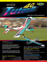
Main
undercarriage leg
Noseleg unit
Spinner
Fuselage
Canopy
L.H. wing
panel
Rudder
Aileron
Fin
Tailplane
R.H. wing
panel
Longitudinal axis
lateral axis
vertical axis
Basic information relating to model aircraft
Any aircraft, whether full-size or model, can be controlled around the three primary axes: vertical (yaw), lateral (pitch) and longitu-
dinal (roll).
When you operate the elevator, the model’s attitude alters around the lateral axis. If you apply a rudder command, the model swings
around the vertical axis. If you move the aileron stick, the model rolls around its longitudinal axis. External influences such as air
turbulence may cause the model to deviate from its intended flight path, and when this happens the pilot must control the model in
such a way that it returns to the required direction. The basic method of controlling the model’s height (altitude) is to vary motor
speed (motor and propeller). The rotational speed of the motor is usually altered by means of a speed controller. Applying up-
elevator also causes the model to gain height, but at the same time it loses speed, and this can only be continued until the model
reaches its minimum airspeed and stalls. The maximum climb angle varies according to the power available from the motor.
Wing section
The wing features a cambered airfoil section over which the air
flows when the model is flying. In a given period of time the air
flowing over the top surface of the wing has to cover a greater
distance than the air flowing under it. This causes a reduction in
pressure on the top surface, which in turn creates a lifting force
which keeps the aircraft in the air. Fig. A
Centre of Gravity (CG)
To achieve stable flying characteristics your model aircraft must
balance at a particular point, just like any other aircraft. It is
absolutely essential to check and set the correct CG position
before flying the model for the first time.
The CG position is stated as a distance which is measured aft
from the wing root leading edge, i.e. close to the fuselage. Sup-
port the model at this point on two fingertips (or - better - use the
MPX CG gauge, # 69 3054); the model should now hang level.
Fig. B
If the model does not balance level, the installed components
(e.g. flight battery) can be re-positioned inside the fuselage. If
this is still not sufficient, attach the appropriate quantity of trim
ballast (lead or plasticene) to the fuselage nose or tail and secure
it carefully. If the model is tail-heavy, fix the ballast at the fuselage
nose; if the model is tail-heavy, attach the ballast at the tail end
of the fuselage.
The longitudinal dihedral is the difference in degrees between
the angle of incidence of the wing and of the tail. Provided that
you work carefully and attach the wing and tailplane to the
fuselage without gaps, the longitudinal dihedral will be correct
automatically.
If you are sure that both these settings (CG and longitudinal
dihedral) are correct, you can be confident that there will be no
major problems when you test-fly the model. Fig. C
Control surfaces, control surface travels
The model will only fly safely, reliably and accurately if the control
surfaces move freely and smoothly, follow the stick movements
in the correct “sense”, and move to the stated maximum travels.
The travels stated in these instructions have been established
during the test-flying programme, and we strongly recommend
that you keep to them initially. You can always adjust them to
meet your personal preferences later on.
Transmitter controls
The transmitter features two main sticks which the pilot moves
to control the servos in the model, which in turn operate the
control surfaces.
The functions are assigned according to Mode A, although other
stick modes are possible.
The transmitter controls the control surfaces as follows:
Rudder (left / right) Fig. D
Elevator (up / down) Fig. E
Aileron (left / right) Fig. F
Throttle (motor off / on) Fig. G
Unlike the other controls, the throttle stick must not return to the
neutral position automatically. Instead it features a ratchet so
that it stays wherever you put it. Please read the instructions
supplied with your radio control system for the method of setting
up and adjusting the transmitter and receiving system.
/