Page is loading ...

1
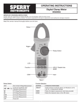
I. DISPLAY FUNCTIONS & SYMBOLS
Rotary Switch
OPERATING INSTRUCTIONS
True-RMS, Autoranging Multimeter
DM6650T
Read this owner’s manual thoroughly before use and save.
AC & DC Voltage Capacitance Test
AC - Alternating Current Hz% Frequency and Duty Cycle Test
DC - Direct Current mA - Millamp
Ohm - Resistance A - Amp
Diode Test NCV Non-Contact Voltage Sensing
Continuity Test OFF Power off
Rotary Switch
Hold/Light Button
LCD Display
Select Button
Functional Buttons
10A MAX
and mA / μA Terminals
COM Terminal
Figure 1
Input Terminal
VΩHz

2
Functional Buttons
Display Symbols
BUTTON OPERATION PERFORMED
HOLD/LIGHT Button Press and hold for 2 seconds to turn the display backlight on or off
HOLD/LIGHT Button Press to step through the available functions
Select Button Press to step through the available functions.
RANGE • Press RANGE to enter the manual ranging mode; the Meter beeps
• Press RANGE to step through the ranges available for the selected function; the Meter beeps
• Press and hold RANGE for 2 seconds to return to autoranging; the Meter beeps
MAX/MIN Press to select the maximum or minimum value. Press and hold to exit.
REL ▲• Press to enter REL mode
• Press again to exit REL mode
Data hold is active
Sleep Mode
Negative reading
AC AC measurement
DC DC measurement
AUTORANGE Auto ranging mode
OL The input value is too large for the selected range
Test of diode
The continuity buzzer is on.
Maximum and Minimum reading.
The battery is low.
Warning: To avoid false readings, which could lead to possible electric shock or personal injury,
replace the battery as soon as the battery indicator appears .
Sensor test is in progress
The REL is on to display the stored value minus the present value
Ω: Ohm. The unit of resistance
kΩ: kilohm. 1 x 10³ or 1000 ohms
MΩ: Megaohm. 1 x 10⁶ or 1,000,000 ohms
V: Volts. The unit of voltage
mV: Millivolt. 1 x 10⁻³ or 0.001 volts.
A: Amperes (amps). The unit of current
mA: Milliamp. 1 x 10⁻³ or 0.001 amperes
µA : Microamp. 1x 10⁻⁶ or 0.000001 amperes
F: Farad. The unit of capacitance
µF : Microfarad. 1 x 10⁻⁵ or 0.000001 farads.
nF : Nanofarad. 1 x 10⁻⁹ or 0.000000001 farads.
Hz: Hertz. The unit of frequency in cycles/second.
kHz: Kilohertz. 1 x 10³ or 1,000 hertz.
MHz: Megahertz. 1 x 10⁶ or1 ,000,000 hertz.
NCV Non-Contact Voltage measurement

3
DANGER is reserved for conditions and actions that are likely to cause serious or fatal injury.
WARNING is reserved for conditions and actions that can cause serious or fatal injury.
CAUTION is reserved for conditions and actions that can cause injury or instrument damage.
II. SAFETY WARNINGS
• This instruction manual contains warnings and safety rules which must be observed by
the user to ensure safe operation of the instrument and retain it in safe condition.
• Read through and understand the instructions contained in this manual before using the instrument.
• Keep the manual at hand to enable quick reference whenever necessary.
• The instrument is to be used only in its intended applications.
• Understand and follow all the safety instructions contained in the manual.
• It is essential that all safety instructions are adhered to.
• Failure to follow the safety instructions may cause injury, instrument damage
The symbol indicated on the instrument means that the user must refer to the related parts in the
manual for safe operation of the instrument. It is essential to read the instructions wherever the symbol
appears in the manual.
DANGER
• Never make measurement on a circuit in which voltage over 1000V exists.
• Do not exceed the CAT rating of the measuring device
• Do not attempt to make measurement in the presence of flammable gases.
The use of the instrument may cause sparking, which can lead to an explosion.
• Never use the instrument if its surface or your hand is wet.
• Do not exceed the maximum allowable input of any measuring range.
• Never open the battery cover during a measurement.
• The instrument is to be used only in its intended applications or conditions.
Use in other than as intended may cause instrument damage or serious personal injury.
WARNING
• Never attempt to make any measurement if any abnormal conditions are noted, such as broken case,
cracked test leads and exposed metal part.
• Do not turn the function selector switch with plugged in test leads connected to the circuit under test.
• Do not install substitute parts or make any modification to the instrument.
Return the instrument to your distributor for repair or recalibration.
• Do not try to replace the batteries if the surface of the instrument is wet.
• Always switch off the instrument before opening the battery compartment cover for battery replacement.
• Set the Function Switch to an appropriate position before starting measurement.
• Firmly insert the test leads.
• Disconnect the test leads from the instrument for current measurement.
• Do not expose the instrument to the direct sun, high temperature and humidity or dewfall.
• Be sure to power off the instrument after use. When the instrument will not be in use for a long period,
place it in storage after removing the batteries.
• Use only a soft cloth dampened with water or neutral detergent for cleaning the meter.
Do not use abrasives, solvents or harsh chemicals. Allow to dry thoroughly before use.
CAUTION

4
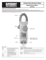
Measurement categories (Over-voltage categories)
To ensure safe operation of measuring instruments, IEC61010 establishes safety standards for various electrical
environments, specified as CAT I through CAT IV, and called measurement categories. Higher-numbered categories
correspond to electrical environments with greater momentary energy, so a measuring instrument designed for CAT III
environments can endure greater momentary energy than one designed for CAT II.
• CAT I: Secondary electrical circuits connected to an AC electrical outlet through a transformer or similar device.
• CAT II: Primary electrical circuits of equipment connected to an AC electrical outlet by a power cord.
• CAT III: Primary electrical circuits of the equipment connected directly to the distribution panel, and feeders
from the distribution panel to outlets.
• CAT IV: The circuit from the service drop to the service entrance, and to the power meter and primary over
current protection device (distribution panel).
Incoming wire Interior wiring
CAT. III
Transformer CAT. II
CAT. I
CAT. IV
Socket
Symbols
Caution, risk of danger, refer to the operating manual before use
Caution, risk of electric shock
AC (Alternating Current)
DC (Direct current)
AC/DC Selectable (Alternating Current/Direct Current)
Earth (ground) Terminal
The equipment is protected throughout by
double insulation or reinforced insulation
Application around and removal from hazardous
live conductors is permitted.
Conforms to Standards of European Union
Designates the product as recyclable
electronic waste per WEEE Directive
III. GENERAL SPECIFICATIONS
• Maximum Voltage between any Terminals and Grounding:
Refer to the different ranges input protection voltage ..
• Fused Protection for mA / μA Input Terminal:600mA H 1000V Ø6.35x31.8mm.
• Fused Protection for 1 OA Input Terminal:10A H 1000V Ø10.3x38.1 mm.
• Display: Maximum reading 6000 (frequency 9999), analogue bar graph 61 segments.
• Measurement Speed: Updates 2-3 times/second.
• Range: Auto or Manual
• Polarity Display: Auto
• Overload indication: Display OL
• Battery Deficiency: Display
• Temperature:
- Operating: 0˚C to +40˚C (32˚F to +104˚F)
- Storage: -10˚C to +50˚C (14˚F to +122˚F)
• Relative Humidity:
- ≤75% @ 0˚C - 30˚C below
- ≤50%@ 30˚C~40˚C
• Battery Type: One piece of 9V (NEDA1604 or 6F22 or 006P).
• Dimensions (HxWxL): (180 x 87 x 47)mm.
• Weight:Approximate 370g (battery included).
• Safety/Compliances:
EN 61010-1,EN 61010-2-030 CAT 1111000V, CAT IV 600Vovervoltage and double insulation standard.
• Certifications:
• Accuracy Specifications:
- Accuracy ± a% reading + b digits guarantee for 1 year.
- Operating temperature 18˚C~28˚C
- Relative Humidity <75%

5
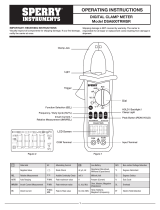
IV. OPERATING INSTRUCTIONS
A. AC/DC VOLTAGE MEASUREMENT (See Figure 2)
To measure voltage, connect the Meter as follows:
1. Insert the red test lead into the input terminal and the black test lead into the COM terminal.
2. Set the rotary switch to or : DC measurement is default or press the SELECT button to
switch show the AC and DC symbols.
3. Connect the test leads across with the object being measured.
The measured value shows on the display and will also show the TRMS value.
Display TRMS Value: If the frequency and duty cycle values are needed at this moment, press the Hz
button to obtain relative data. The input amplitude concerning these two aspects should follow the
requirements as stated below:
- Input Amplitude: (DC electric level is zero)
- Input Amplitude: ≥rangeX30%
- Frequency respouse: ≤1kHz
NOTE: In each range, the Meter has an input impedance of 10Ω except the mV range where the input
impedance is 3000MΩ. This loading effect can cause measurement errors in high impedance
circuits. If the circuit impedance is less than or equal to 10KΩ, the error is negligible (0.1 % or less).
B. AC/DC CURRENT MEASUREMENT (See Figure 3)
To measure current, connect the Meter as follows:
1. Insert the red test lead into the mA / μA or 10AMax input terminal and the black test lead
into the COM terminal.
2. Set the rotary switch to μA, mA, or A.
3. The Meter defaults to the DC current measurement mode. show the AC and DC symbols current
measurement function, press the SELECT button.
4. Connect the test lead in series to the return circuit to be tested.
The measured value shows on the display and will also show the TRMS value.
5. Press Hz% to obtain the frequency and duty cycle value.
Display TRMS Value: If the frequency and duty cycle values are needed, press the Hz/% button
to obtain relative data. The input amplitude concerning these two aspects should follow the
requirements as stated below:
- Input Amplitude: (DC electric level is zero)
- lnputAmplitude: ≤rangeX30%
- Frequency response: ≤1kHz
NOTE:
• If the value of current to be measured is unknown, use the maximum measurement position, and reduce the range step by step until a
satisfactory reading is obtained.
• Each measurement time for >5A current should be less than 10 seconds and the interval time
between 2 measurements should be greater than 15 minutes.
• When current measurement has been completed, disconnect the connection between the testing leads
and the circuit under test, and remove the testing leads from the input terminals of the Meter.
C. MEASURING RESISTANCE (See Figure 4)
To measure resistance, connect the Meter as follows:
1. Insert the red test lead into the input terminal and the black test lead into
the COM terminal.
2. Set the rotary switch to Ω resistance measurement (Ω) is default or press the SELECT button
to select Ω measurement mode.
3. Connect the test leads across with the object being measured. If there is lead on the resistor
or SMT resistor. The measured value shows on the display.
NOTE:
• The test leads can add 0.2Ω to 0.5Ω of error to resistance measurements. To obtain precision
readings in low-resistance measurement, short-circuit the input terminals beforehand and use
the relative measurement function button REL ▲ .This will automatically subtract the value
measured when the testing leads are short circuited from the reading.
• If Ω reading with shorted test leads is not ≤0.5Ω, check for loose test leads or other reasons.
• For high-resistance measurements (>1MΩ), it is normal to take several seconds to obtain a
stable reading. To obtain stable reading, use shorter test leads to carry out readings.
• The LCD displays OL indicating open-circuit for the tested resistor or the resistor value is
higher than the maximum range of the Meter.
• When the resistance measurement has been completed, disconnect the connection between
the testing leads and the circuit under test, and remove the testing leads from the input terminals of the Meter.
Figure 2
Figure 3
Figure 4
VΩHz
VΩHz

6
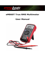
D. TESTING FOR CONTINUITY (See Figure 5)
To test for continuity, connect the Meter as follows:
1. Insert the red test lead into the input terminal and the black test lead into the COM terminal.
2. Set the rotary switch to Ω and press SELECT button to select the measurement mode.
3. The buzzer sounds continuously if the resistor to be tested is <10Ω.
The buzzer does not sound if the resistor to be tested is >35Ω.
NOTE:
• Open circuit voltage is around 0.45V
• When continuity testing has been completed, disconnect the connection between
the testing leads and the circuit under test, and remove the testing leads away from
the input terminals of the Meter.
E. TESTING DIODES (See Figure 6)
To test diodes, connect the Meter as follows:
1. Insert the red test lead into the input terminal and the black test lead
into the COM terminal.
2. Set the rotary switch to Ω and press the SELECT button to select measurement mode.
NOTE:
• In a circuit, a good diode should still produce a forward voltage drop reading of 0.5V to 0.8V;
however, the reverse voltage drop reading can vary depending on the resistance of other
pathways between the probe tips.
• Connect the test leads to the proper terminals as said above to avoid error display. The LCD
will display OL indicating diode being tested is open or polarity is reversed. The unit of diode
is Volt (V), displaying that the forward voltage drop readings.
• When diode testing has been completed, disconnect the connection between the
testing leads and the circuit under test, and remove the testing leads from the input terminals
of the Meter.
F. CAPACITANCE MEASUREMENT (See Figure 7)
To measure capacitance, connect the Meter as follows:
1. Insert the red test lead into the input terminal and the black test lead
into the COM terminal.
2. Set the rotary switch to Ω and press SELECT button to select nF measurement mode.
• At that time, the Meter will display a fixed value as below which is the Meter internal
fixed distributed capacitance value. To ensure accuracy when measuring a small value
of capacitance, the tested value must subtract this value, REL mode can help on that.
Around 10nF
3. Connect the test leads across with the object being measured.
The measured value shows on the display.
NOTE:
• It takes a longer time when the tested capacitor is more than 100μF
• The LCD displays OL indicating the tested capacitor is shorted or it
exceeds the maximum range.
• When capacitance measurement has been completed, disconnect all connections
between the test leads, capacitor and the Meter.
G. FREQUENCY MEASUREMENT (See Figure 7)
To measure frequency, connect the Meter as follows:
1. Insert the red test lead into the input terminal and the black test lead
into the COM terminal.
2. Set the rotary switch to Hz%; frequency measurement (Hz) is default or press
Hz% button to select Hz measurement mode.
3. Connect the test leads across with the object being measured.
The measured value shows on the display.
4. If you need to measure duty cycle, press Hz% button to select % measurement mode
NOTE:
• Input Amplitude: (DC electric level is zero)
When 10Hz~10MHz: 200mV≤a ≤30Vrms
• When frequency measurement has been completed, disconnect the connection
between the testing leads and the circuit under test, and remove the testing leads
away from the input terminals of the Meter.
Figure 5
Figure 6
Figure 7
Figure 8
VΩHz
VΩHz
VΩHz
VΩHz

7
H. NCV (NON-CONTACT VOLTAGE)
To use the meter as a NCV (Non-Contact Voltage) Sensor, set it up as follows:
1. From the Off position, set the rotary switch to the NCV.
2. The meter will now function as a non-contact voltage sensor to indicate the presence of nearby AC voltage.
3. The meter will display a voltage reading when detecting the electric field of AC voltage while in NCV mode.
NOTE:
• The NCV sensor location is marked on the top of the meter by a ▲ .
I. OPERATION OF HOLD MODE
To avoid possibility of electric shock, do not use Hold mode to determine if circuits are without power.
The Hold mode will not capture unstable or noisy readings. The Hold mode is applicable to all measurement functions.
• Press HOLD to enter Hold mode; the Meter beeps.
• Press HOLD again to exit Hold mode; the Meter beeps.
• In Hold mode, is displayed.
J. RANGE BUTTON
• Press RANGE to enter the manual ranging mode; the Meter beeps.
• Press RANGE to step through the ranges available for the selected function; the Meter beeps.
• Press and hold RANGE for over 2 seconds to return to autoranging; the Meter beeps.
NOTE:
• When using the manual range mode, always start from the highest range and work your way down through the ranges
until you find the appropriate range.
K. MAX MIN BUTTON
• Press MAX MIN to start recording of maximum and minimum values. This sets the display to show high (MAX) and low (MIN)
readings. The Meter enters the manual ranging mode after pressing MAX MIN button.
• Press and hold MAX MIN for over 2 seconds to exit the MAX MIN mode and return to the present measurement range.
L. RELATIVE VALUE MODE
The REL mode applies to all measurement functions except frequency/duty cycle measurements.
It subtracts a stored value from the present measurement value and displays the result.
For instance, if the stored value is 20.0V and the present measurement value is 22.0V, the reading would be 2.0V. If a new
measurement value is equal to the stored value then it will display O.OV.
To enter or exit REL mode:
• Press REL ▲ to enter REL mode, and the present measurement range is locked and display "0"as the stored value.
• Press REL ▲ again to reset the stored value and exit REL mode.
M. SELECT BUTTON
Used for selecting the required measurement function when there is more than one function at one position of the rotary switch.
N. DISPLAY BACKLIGHT
• Press and hold the HOLD/LIGHT button for over 2 seconds to turn the Display Backlight on.
• The display backlight will automatically turn off around after 10 seconds.
O. AUTO POWER OFF
• To conserve battery life the meter powers off automatically after 15 minutes of non use.
• To disable Auto Off, press and hold the SELECT button while turning the rotary switch from the Off position when turning the
meter on. Auto Off will be disabled until the next time the meter is turned off.
WARNING

8
V. ACCURACY SPECIFICATIONS
DC VOLTAGE
RANGE RESOLUTION ACCURACY
60mV 0.01mV ±(0.8%+3)
600mV 0.1mV
6V 0.001V
±(0.5%+1)
60V 0.01V
600V 0.1V
1000V 1V ±(1.0%+3)
- True RMS is applicable from 10% of range to
100% of range.
- AC crest factor can be up to 3.0 except
1000V where it is 1.5.
- A residual reading of 10 digits with test leads
shorted, will not affect stated accuracy.
AC VOLTAGE
RANGE RESOLUTION ACCURACY
60mV 0.01mV ±(1.2%+5) ±(2.0%+5)
600mV 0.1mV
6V 0.001V
±(1.0%+3) ±(1.5%+5)
60V 0.01V
600V 0.1V
1000V 1V ±(1.2%+5) ±(3.0%+5)
CAPACITANCE
RANGE RESOLUTION ACCURACY
40nF 0.01nF
±(3.0%+5)
400nF 0.1nF
4μF 0.001μF
40μF 0.01μF
400μF 0.1μF ±(4.0%+5)
4000μF 1μF unspecified
RESISTANCE
RANGE RESOLUTION ACCURACY
600Ω0.1Ω±(1.2%+2)
6kΩ0.001kΩ
±(1.0%+2)
60kΩ0.01kΩ
600KΩ0.1kΩ
6MΩ0.001MΩ±(1.2%+2)
60MΩ0.01MΩ+(1.5%+2)
DC CURRENT
RANGE RESOLUTION ACCURACY
600μA 0.1μA
(1.0%+3)
6000μA 1μA
60mA 0.01mA
600mA 0.1mA
6A 0.001A
(1.2%+5)
10A 0.01A
- When ≥5A: Continuous measurement is allowed.
- When >5A: Continuous measurement less than
10 seconds at an interval more than 15 minutes.
AC CURRENT
RANGE RESOLUTION ACCURACY
600μA 0.1μA
(1.2%+5)
6000μA 1μA
60mA 0.01mA
(1.5%+5)
600mA 0.1mA
6A 0.001A
(2.0%+5)
10A 0.01A
- When ≥5A: Continuous measurement is allowed.
- When >5A: Continuous measurement less than
10 seconds at an interval more than 15 minutes.
- True RMS is applicable from 10% of range to
100% of range.
- AC crest factor can be up to 3.0 except 1000V
where it is 1.5.
- A residual reading of 10 digits with test leads
shorted, will not affect stated accuracy.
FREQUENCY
RANGE RESOLUTION ACCURACY
10Hz~10MHz 0.01Hz (0.1%+4)
- Overload Protection: 1000V DC/AC
- Input Amplitude: (DC electric level is zero)
- When measuring on line frequency or duty cycle
under AC Voltage and Current measurement mode,
the input amplitude and frequency response must
satisfy the following requirement:
Input amplitude ≥range x 30%
Frequency response: ≤1kHz
DIODE TEST
RESOLUTION REMARKS OVERLOAD PROTECTION
0.001V Open circuit
voltage around 2.8V 1000V DC/AC
CONTINUITY TEST
RESOLUTION OVERLOAD PROTECTION
0.1Ω 1000V DC/AC
- Open circuit voltage is around 0.45V.
- Broken circuit resistance value is around > 350Ω,
the buzzer does not beep.
- Good circuit resistance value is ≤10Ω on, the buzzer
beeps continuously.

9
VI. MAINTENANCE
A. Replacing the Battery (See Figure 12)
To replace the battery:
1. Turn the Meter”s power off and remove all connections from the terminals.
2. Remove the screw from the tilt stand/battery compartment and
separate the battery compartment and the tilt stand from the case bottom.
3. Remove the battery from the battery compartment.
4. Replace the battery with a new 9V battery (attached to the tilt stand).
5. Rejoin the tilt stand/battery compartment with the case bottom and
reinstall the screw.
B. Testing the Meters Fuse (See Figure 13)
To test the meter’s fuse connect the Meter as follows:
1. Insert the red test lead into the V input terminal.
2. Set the rotary switch to Ω resistance measurement (Ω) is default or press the
SELECT button to select Ω measurement mode.
3. Insert the other end of the test lead into the 10AMAX and observe the reading on
the display. You should see a reading <0.5 Ohms. If you see (OL), the fuse is bad.
4. Repeat step (4.) for the mA / μA terminal.
NOTE:
• When the fuse test has been completed, disconnect the connection between the
testing leads and the circuit under test, and remove the testing leads from the input
terminals of the Meter.
C. Replacing the Fuses (See Figure 13)
To replace the meter’s fuse:
1. Turn the Meter power off and remove all the connections from the terminals.
2. Remove the screw from the tilt stand/battery compartment and separate
the battery from the case bottom.
3. Remove the two screws from the case bottom, and separate the case top from the case bottom.
4. Remove the fuse by gently prying one end loose, then take out the fuse from its bracket.
5. Install ONLY replacement fuses with the identical type and specification as follows and make sure the fuse is fixed firmly in the
bracket.
mA / μA range: F1, 600mA H 1000V, Ø6.35x31.8mm
10A range: F2, 10A H 1000V, Ø10.3 x 38.1 mm
6. Rejoin the case bottom and case top, and reinstall the screw.
7. Rejoin the tilt stand/battery compartment and case bottom, and reinstall the screw.
Figure 12
Figure 13
NON-CONTACT VOLTAGE DETECTION
RANGE RESOLUTION ACCURACY
50VAC
50Hz/60Hz
0mm: buzzer beep (insulated wire)
120VAC 0-5mm: buzzer beep (electric outlet)
500VAC <12in: buzzer beep

10
Sperry Instruments
800-645-5398
Menomonee Falls, WI 53051
sperryinstruments.com SPR_TL_066_1017
SPERRY INSTRUMENTS LIMITED LIFETIME WARRANTY
Subject to the exclusions and limitations detailed below, Sperry Instruments provides a limited lifetime warranty on products
of its manufacture will be free from defects in materials and workmanship under normal use and service.
Limited
Limited means that Sperry Instruments warrants to the original purchasers of products from Sperry Instruments authorized
distributors at the time of shipment such products shall be free of defects in material and workmanship while the tool is used
under normal working conditions. Standard wear and tear, dulling over time, overloading, misuse, and acts of God are not
covered under warranty. This warranty does not cover batteries, fuses, or test leads.
When a warranty claim arises, the purchaser must contact Sperry Instruments. If the defect comes under the terms of this
limited warranty, Sperry Instruments will arrange, at its sole discretion, one of the following options:
• Product will be replaced
The purchaser is solely responsible for determining the suitability of Sperry products for the purchaser’s use or resale, or
for incorporating them into articles or using them in the purchaser’s applications. The distributor is authorized to extend the
foregoing limited warranty to its original purchasers in connection with the sales of Sperry products, provided that such products
shall not have been altered by the distributor. The distributor shall be fully responsible for any warranties the distributor makes to
its purchasers which are broader or more extensive than Sperry’s limited warranty.
Lifetime Warranty
Warranty Limitation: The forgoing warranties are exclusive and are in lieu of all other express and implied warranties whatsoever,
including but not limited to implied warranties of merchantability and fitness for a particular purpose. The foregoing warranties
do not cover ordinary wear and tear, abuse, misuse, overloading, alterations, products which have not been installed, operated
or maintained in accordance with Sperry’s written instructions. Test leads, fuses, batteries and calibration are not covered under
any implied warranty. “Lifetime” of products that are no longer offered by Sperry will be either repaired or replaced with an item
of Sperry Instruments choice of similar value. Lifetime is defined as 5 years after Sperry discontinued manufacturing the product,
but the warranty period shall be at least ten years from date of purchase. Original proof of purchase is required to establish
original ownership of product.
No warranty will be honored unless an invoice or other proof of purchase date is provided to Sperry Instruments. Hand written
receipts or invoices will not be honored.
©2016 Product Power, LLC All rights reserved.
- See more at: https://www.sperryinstruments.com/en/Resources/Warranty-Information
/