Page is loading ...

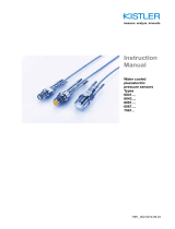
Instruction
Manual
Piezoelectric
Pressure Sensors
Type 601C…
Type 603C…
60xC_002-741e-06.23


Foreword
60xC_002-741e-06.23 Page 1
Foreword
Thank you for choosing a Kistler quality product charac-
terized by technical innovation, precision and long life.
Information in this document is subject to change without
notice. Kistler reserves the right to change or improve its
products and make changes in the content without obli-
gation to notify any person or organization of such
changes or improvements.
© 2015 … 2023 Kistler Group. All rights reserved. Except
as expressly provided herein, no part of this manual may
be reproduced for any purpose without the express prior
written consent of Kistler Group. Kistler Group products
are protected by various intellectual property rights. For
more details visit www.kistler.com. The Kistler Group in-
cludes Kistler Holding AG and all its subsidiaries in
Europe, Asia, the Americas and Australia.
Kistler Group
Eulachstrasse 22
8408 Winterthur
Switzerland
Tel. +41 52 224 11 11
www.kistler.com

Piezoelectric Pressure Sensor Type 601C/603C
Page 2 60xC_002-741e-06.23
Content
1. Introduction ................................................................................................................................. 4
2. General functional description .................................................................................................. 5
2.1 PE pressure sensors ........................................................................................................... 6
2.1.1 Measuring chain (PE) ............................................................................................. 6
2.1.2 Characteristics of PE sensors and measuring chains............................................ 7
2.2 IEPE pressure sensors ....................................................................................................... 8
2.2.1 Measuring chain (IEPE) ......................................................................................... 8
2.2.2 Characteristics of IEPE sensors and measuring chains ........................................ 9
3. Equipment .................................................................................................................................. 10
3.1 Sensor housing ................................................................................................................. 10
3.2 Sensor dummy .................................................................................................................. 11
3.3 Seal (Sensor) .................................................................................................................... 11
3.4 Floating clamp nut ............................................................................................................. 11
3.5 Adapter .............................................................................................................................. 12
3.6 Seal (adapter) ................................................................................................................... 13
4. Mounting & installation ............................................................................................................. 14
4.1 Mounting options ............................................................................................................... 14
4.1.1 Direct vs. adapter mounting (sensors with standard housing) ............................. 14
4.1.2 Direct mounting (sensor with short housing) ........................................................ 15
4.1.3 Flush vs. passage mounting ................................................................................ 15
4.2 Installation ......................................................................................................................... 18
4.2.1 Floating clamp nut and adapter ............................................................................ 18
4.2.2 Connector extender Type 6482A ......................................................................... 19
4.2.3 Cabling ................................................................................................................. 20
4.3 Manufacturing of mounting hole ........................................................................................ 21
4.3.1 Direct flush mounting (ISO) .................................................................................. 21
4.3.2 Direct flush mounting (ANSI) ................................................................................ 23
4.3.3 Direct passage mounting (ISO) ............................................................................ 25
4.3.4 Direct passage mounting (ANSI) .......................................................................... 27
4.3.5 Adapter Mounting (ISO) ....................................................................................... 29
4.3.6 Adapter Mounting (ANSI) ..................................................................................... 30
5. Operational Considerations ..................................................................................................... 31
5.1 Electrical noise .................................................................................................................. 31
5.1.1 PE sensors ........................................................................................................... 31
5.1.2 IEPE sensors ........................................................................................................ 33
5.2 Ground Loops ................................................................................................................... 36
5.3 Thermal effects ................................................................................................................. 37
5.3.1 Thermal Zero Shift................................................................................................ 37
5.3.2 Thermal Sensitivity Shift ....................................................................................... 38
5.3.3 Thermal Shock ..................................................................................................... 39
5.4 High frequency response, low-pass filter and sampling rate ............................................ 42
6. Maintenance and calibration .................................................................................................... 43
6.1 Maintenance ...................................................................................................................... 43
6.1.1 Sensors ................................................................................................................ 43
6.1.2 Connectors ........................................................................................................... 43
6.2 Calibration ......................................................................................................................... 45
6.3 Warranty ............................................................................................................................ 45

Introduction
60xC_002-741e-06.23 Page 3
6.4 Disposal instructions for electrical and electronic equipment ............................................ 45
7. Conformity declaration .............................................................................................................. 46
Total pages 46

Piezoelectric Pressure Sensor Type 601C/603C
Page 4 60xC_002-741e-06.23
1. Introduction
First of all we would like to thank you for trusting Kistler
and using one of our sensors for your measurements.
Please take the time to thoroughly read this instruction
manual. It will help you with the installation, maintenance
and use of this product.
To the extent permitted by law Kistler does not accept
any liability if this instruction manual is not followed or
products other than those listed under Accessories are
used.
This manual covers several general purpose piezoelec-
tric pressure sensors that are suited for a variety of appli-
cations. Please see below list for an overview of sensors
covered by this manual:
601CAA
601CAB
601CBA00001.5
601CBA00003.5
601CBA00007.0
601CBA00014.0
601CBA00035.0
601CBA00070.0
601CBA00250.0
603CAA
603CAB
603CBA00014.0
603CBA00035.0
603CBA00070.0
603CBA00350.0
603CBA00690.0
603CBA01000.0
This manual might have changed since last downloaded,
please check the Kistler webpage for the newest version.
For full sensor specifications please refer to the data
sheet. If you need any additional help beyond what can
be found either on-line or in this manual, please don’t
hesitate to contact your local Kistler sales offices.

General functional description
60xC_002-741e-06.23 Page 5
2. General functional description
Due to their high natural frequencies, piezoelectric pres-
sure sensors can be used for a variety of applications
where dynamic pressures need to be measured. Another
unique characteristic of piezoelectric pressure sensors is
their ability to measure small pressure fluctuations that
are superimposed on top of high static pressures with
highest resolution.
Please notice that as with any piezoelectric sensor, true
static measurements are impossible. Piezoresistive pres-
sure sensors are the right choice when measuring static
pressures.
At the core of a piezoelectric pressure sensor there’s a
synthetic crystal, with quartz being the most used materi-
al by sensor manufacturers. Kistler additionally grows
own high performance crystals called PiezoStar. Sensors
based on PiezoStar crystals show several advantages
over quartz based sensors as for example higher operat-
ing temperatures, higher sensitivities, etc.
The pressure to be measured acts on the sensor’s dia-
phragm and coverts it into a proportional force which then
acts on the crystal. The compressed crystal produces a
charge which is proportional to the pressure. The charge
itself is being picked-up by the sensors electrode and
taken to the plug. Finally the charge signal needs to be
converted, by a charge amplifier, into a voltage to be
read.
Two variants of piezoelectric sensors are available,
charge output (PE) and voltage output (IEPE). The fol-
lowing chapters will give you an overview on the charac-
teristics of both variants, with their corresponding ad-
vantages and disadvantages compared to each other
and with that give you the chance to select the best op-
tion for your corresponding measurement task.

Piezoelectric Pressure Sensor Type 601C/603C
Page 6 60xC_002-741e-06.23
2.1 PE pressure sensors
Piezoelectric pressure sensors with charge output are re-
ferred to as PE throughout this document.
2.1.1 Measuring chain (PE)
PE sensors deliver a charge signal; hence the sensitivity
is given as pico-coulombs per unit of pressure (e.g.
pC/bar or pC/psi). Pressure applied to a PE sensor pro-
duces a negative going charge signal (hence the nega-
tive sensitivity of PE sensors), which then is turned into a
positive voltage signal by the external charge amplifier.
Contrary to IEPE sensors, PE sensors don’t need to be
powered as a charge signal is produced as soon as
pressure is applied to the piezoelectric material. However
a special high impedance cable supplied by Kistler is es-
sential to transport the incredibly small charges.
Kistler offers dual-mode (PE and IEPE) multi-channel
charge amplifiers with integrate DAQ (digital and analog
outputs) which can be connected directly to a PC through
an Ethernet cable or through its analog outputs to an ex-
ternal DAQ system. Alternatively Kistler offers single-
mode charge amplifiers with analog outputs which can
then be connected to an external DAQ system.

General functional description
60xC_002-741e-06.23 Page 7
2.1.2 Characteristics of PE sensors and measuring chains
Here’s an overview on the main characteristics of PE
sensors and measuring chains:
Dynamic and quasi-static pressure measurements
As already mentioned true static measurements are
impossible with any piezoelectric sensor. However
with PE sensors quasi-static measurements can be
performed. The duration over which so-called quasi-
static measurements can be performed depends on
the insulation resistance of the sensor and its con-
necting cable (the higher the better), and the time
constant adjusted on the external charge amplifier.
Extreme wide operating temperature range
Since no electronics are built into the sensor it’s pos-
sible to operate and measure within an extreme tem-
perature range. The operating temperature range is
shown on the data sheet and is wider for sensors
based on PiezoStar than quartz crystals.
Adjustable FSO pressure range
The Full Scale Output (usually ±10 V) pressure range
can be adjusted by the external charge amplifier. This
means that the same sensor can be used to measure
a few mbar or, by changing the measuring range on
the charge amplifier, a few hundred bars. This makes
the measurement chain very flexible so that it can be
used for different measurement tasks and be adjusted
to whatever scale is needed.
Need for special high impedance cables
The charge signal of the PE sensor needs to be
transmitted through a special high insulation re-
sistance cable that can be purchased at Kistler. The
use of cheaper standard cables leads to drift and is
therefore not recommended. Also, high impedance
cables should be protected against humidity.
Connectors need to be kept clean
The connectors (of the sensor, high insulation re-
sistance cable and charge amplifier), must be protect-
ed against contamination and humidity in order to
keep the high insulation. All plugs must be kept as
clean and dry as possible and should therefore always
be capped in order to keep contamination out when
not connected.

Piezoelectric Pressure Sensor Type 601C/603C
Page 8 60xC_002-741e-06.23
2.2 IEPE pressure sensors
Piezoelectric pressure sensors with voltage output are re-
ferred to as IEPE or Piezotron sensors throughout this
document. IEPE stands for Integrated Electronics Piezo
Electric and refers to an industry standard for piezoelec-
tric sensors with integrated electronic circuits that convert
a charge into a voltage signal. Piezotron is the registered
trademark of Kistler for IEPE sensors.
2.2.1 Measuring chain (IEPE)
IEPE sensors deliver a voltage signal; hence the sensitiv-
ity is given as Millivolt per unit of pressure (e.g. mV/bar or
mV/psi). Pressure applied to an IEPE sensor produces a
positive voltage signal (hence the positive sensitivity of
IEPE sensors).
Contrary to PE sensors, IEPE sensors need to be pow-
ered due to the built-in electronics. However a standard
two-wire cable suffices to power the sensor and transmit
the voltage signal to an IEPE-coupler. An IEPE-Coupler
is an electronic circuit that supplies constant current exci-
tation to IEPE sensors and decouples the subsequent
voltage signal. So you just see the pressure signal.
Kistler offers dual-mode (PE and IEPE) multi-channel
charge amplifiers with integrated IEPE-Coupler and DAQ
(digital and analog outputs) which can be connected di-
rectly away to a PC through an Ethernet cable or through
its analog outputs to an external DAQ system. Alterna-
tively Kistler offers single or multi-channel IEPE-Couplers
that can then be connected to an external DAQ system
and of course IEPE sensors can directly be connected to
any IEPE compatible DAQ.

General functional description
60xC_002-741e-06.23 Page 9
2.2.2 Characteristics of IEPE sensors and measuring chains
Only dynamic pressure measurements
Whilst quasi-static measurements are possible with
PE sensors, this is not the case for IEPE due to the
fixed time constant in the built-in charge amp. Never-
theless IEPE sensors are well suited to measure dy-
namic pressures and pressure pulsations.
Limited operating temperature range
The operating temperature range of IEPE sensors is
limited due to the integrated electronics and is shown
in the data sheet.
Fixed FSO pressure range
The Full Scale Output (usually nominal ±5 V) pressure
range of IEPE sensors is fixed by the settings of the
integrated electronics and can’t be adjusted.
Use of standard cables
IEPE sensors can be operated with standard two-wire
cables. Standard cables can be used in harsh envi-
ronments and are less sensitive to dirty and humid
environments. IEPE sensors are also the preferred
choice when very long cables are needed.
Compatible with IEPE systems
IEPE sensors can be connected directly to
IEPE-DAQ’s or to a DAQ, through an external IEPE-
coupler, if already available, without the need to pur-
chase an external charge amplifier. Sometimes an ex-
ternal IEPE-coupler might offer some technical ad-
vantages, as for example a higher power supply to
drive longer cables or power supplies with lower noise
for a better signal quality.

Piezoelectric Pressure Sensor Type 601C/603C
Page 10 60xC_002-741e-06.23
3. Equipment
3.1 Sensor housing
PE pressure sensors come with a standard or short
housing, whereas IEPE sensors are only available with a
standard housing. Please notice that the connector for
the short housing is different than for the standard hous-
ings.
T
y
pe Output si
g
nal Housin
g
Connecto
r
60xC
AA
Char
g
e
(
PE
)
Standard 10-32
60xC
A
B Char
g
e
(
PE
)
Shor
t
M4
60xCBA… Volta
g
e
(
IEPE
)
Standard 10-32
Whenever possible it’s recommended to use a piezoelec-
tric sensor with a standard housing.
The sensor version with short housing was primarily de-
veloped to be used with a connector extender of Type
6482A.
Fig. 1: Standard housing vs. short housing

Equipment
60xC_002-741e-06.23 Page 11
3.2 Sensor dummy
It’s recommended to replace the sensor by a sensor
dummy when not being used for measurements or tests
where pressures may exceed the maximum overload
pressure indicated in the datasheet. Using a dummy sen-
sor allows prolonging the life time of the sensor resp.
prevents the sensor being damaged by a too high pres-
sure.
T
y
pe Housin
g
Connecto
r
6487A
A
Standard 10-32
6487AB Shor
t
M4
3.3 Seal (Sensor)
Below table lists all available sensor seals. Five replace-
able copper seals of Kistler Type 1131BA0.15 are part of
each sensor delivery. The Cu and Ni seals must be re-
placed after each sensor deinstallation. The S.S. seal
can be used up to 10 times if only tighten at 2Nm (for
pressures up to ca. 250 bar), but only once if tightened
with ca. 4 to 5Nm (for highest pressures).
T
y
pe Material
1131BA0.15 Cu
1131BB0.20 Ni
1131BC1.15 Stainless Steel 1.4305
(for RTV recess mounting)
3.4 Floating clamp nut
All of the piezoelectric pressure sensors listed in the in-
troduction of this instruction manual utilize a floating
clamp nut to secure the sensor either into a mounting
adapter or into an appropriately dimensioned mounting
bore (direct mounting). The next chapters will provide
some more details on direct and adapter mounting of the
sensors.
The floating clamp nut needs to be ordered separately as
there are different options to choose from. The table be-
low lists all available types.
T
y
pe Hex Thread
6423B00 8 mm M7x0.75
6423B11 9/32” 5/16-24 UNF
Fig. 2: Floating clamp nut

Piezoelectric Pressure Sensor Type 601C/603C
Page 12 60xC_002-741e-06.23
3.5 Adapter
Fitting sensors into a mounting adapter greatly simplifies
the installation process (for more information see “Mount-
ing Options” chapter). Please find below an overview of
available adapters and floating clamp nuts that fit the cor-
responding adapter:
Type Material
Adapter
Thread Hex Floating
Clamp Nut
6503C0A Stainless Steel
(
1.4542
)
M10x1 11 mm 6423B00
6503C1A Stainless Steel
(
1.4542
)
3/8-24
UNF 7/16” 6423B11
6503C0D PEEK GF30
(
Ground Isolated
)
M10x1 11 mm 6423B00
6503C1D PEEK GF30
(
Ground Isolated
)
3/8-24
UNF 7/16” 6423B11
6503C3A Stainless Steel
(
1.4542
)
1/8-27
NPTF 7/16” 6423B11
6507B0A Stainless Steel
(
1.4542
)
M3x0.5 8 mm 6423B00
6507B1A Stainless Steel
(
1.4542
)
5-40 UNC 11/32” 6423B11
6509B Stainless Steel
(
1.4542
)
M14x1.25 18 mm 6423B00
Stainless steel adapters (except Type 6503C3A) include
one tube of lubrication grease Type 1063. It’s strongly
recommended to apply a thin film of lubricating grease of
Kistler Type 1063 to the external thread of the adapter
before mounting. The lubrication prevents seizing of the
threads and surfaces when demounting the adapter as
well as sealing against high pressures.
Below list gives an overview on the approximate pres-
sures up to which the adapters are tight (check chapter
4.2.1 for corresponding tightening torques).
6503CxA (with S.S. seal) 1 000 bar / 14 500 psi
6503CxA (with Cu seal) 300 bar / 4 350 psi
6503CxD (w/o seal)1) 100 bar / 1 450 psi
6503C3A (w/o seal) 1 000 bar / 14 500 psi2)
6507BxA (with Cu seal) 300 bar / 4 350 psi
6509B (with Cu seal) 300 bar / 4 350 psi
1) Max. static temperature 100°C (212°F), use compensation sleeve
(delivered with 6503CxD adapters) from 60°C (140°F) on. To be
mounted between sensor and floating clamp nut.
2) Reduced max. pressure for materials with hardness higher than
200 HB.
Fig. 3: Kistler lubrication grease,
Type 1063

Equipment
60xC_002-741e-06.23 Page 13
3.6 Seal (adapter)
One replaceable seal of each type is part of the adapter de-
livery. Stainless steel gaskets are recommended for high
pressure applications and/or hard sealing surfaces while
copper gaskets are recommended for low pressure applica-
tions, gaseous media and/or soft sealing surfaces. Below
table lists all seal types in case replacement is needed.
T
y
pe Material Adapte
r
1113C0B Stainless Steel 1-4301 / 304 6503C0A
1113C0C Cu
1113C1B Stainless Steel 1-4301 / 304 6503C1A
1113C1C Cu
1117B0C Cu 6507B0A
6507B1
A
1111 Cu 6509B

Piezoelectric Pressure Sensor Type 601C/603C
Page 14 60xC_002-741e-06.23
4. Mounting & installation
4.1 Mounting options
4.1.1 Direct vs. adapter mounting (sensors with standard housing)
Sensors with charge output (PE) and voltage output (IE-
PE) are available with standard housing. Sensors with a
standard housing can either be installed directly or with
an adapter.
Direct Mounting
When the mounting location space is restricted, the sen-
sor can be located in an appropriately dimensioned
mounting bore, and then held in place with a floating
clamp nut. Please note that for a reliable and accurate
pressure measurement a precise machining of the
mounting hole with special reamer and taps is required
(for details on mounting hole fabrication please see cor-
responding chapter).
Adapter Mounting
Fitting sensors into a mounting adapter greatly simplifies
the installation process (when space and wall thickness
are not a premium). Use of a Kistler mounting adapter
will eliminate the need to provide a precise mounting con-
figuration and allow the installer to provide only a thread-
ed hole of the size and depth required for the adapter se-
lected. Special reamers or taps are not required when us-
ing an adapter (for details on mounting thread fabrication
please see corresponding chapter).
Adapter seal
(e.g. 1113C0C)
Adapter
(e.g. 6503C0A)
Fig. 4: Direct vs. adapter mounting
of sensor with standard housing
Floating Clamp Nut
(e.g. 6423B00)
Sensor seal
(e.g. 1131Bx)
Sensor with standard housing
(e.g. 601CAA, 601CBAxxxxx.x)
Cable with 10-32 connector
(e.g. 1631C)

Mounting & installation
60xC_002-741e-06.23 Page 15
4.1.2 Direct mounting (sensor with short housing)
Sensors with charge output (PE) are also available with
short housing. For the mounting of these sensors a con-
nector extender of Type 6482A is required. This mount-
ing form is mostly only used where mechanical structures
cannot be weakened.
Connector extenders are made to order and are therefore
not stock items (unlike floating clamp nuts of Type
6423B). Customers can choose between three different
connectors, two different threads and a variable length
(see sensor datasheet for different options and ordering
key).
Please note that for a reliable and accurate pressure
measurement a precise machining of the mounting hole
with special reamers and taps is required (same as for di-
rect mounting of sensors with standard housing).
4.1.3 Flush vs. passage mounting
Ideally for best accuracy, minimal rise time and max. fre-
quency response a pressure sensor should be mounted
with its sensing diaphragm flush with the pressure cham-
ber inner wall. Flush mounting of pressure sensors is de-
sirable for minimizing turbulences, avoiding cavity effects
or avoiding an increase in a chamber volume too.
However sometimes, due to access restrictions to the
pressure chamber or due to severe environments (e.g.
particle impingement, high temperatures, etc.), this is not
possible and therefor a passage mounting is required.
Fig. 5: Direct mounting of sensor with
short housing
Sensor seal
(e.g. 1131Bx)
Sensor with short
housing
(601CAB)
Cable with 10-32,
BNC or
TNC connector
Connector Extender
(
6482Axxx
)
Max. operating
temperature
of connector
extender
165°C/329°F
Fig. 6: Flush (direct / adapter) vs. passage (direct/ adapter) mounting

Piezoelectric Pressure Sensor Type 601C/603C
Page 16 60xC_002-741e-06.23
With passage mountings, acoustic oscillations may occur
in the cavity if the gas to be measured is stimulated by a
fast pressure change at the entrance of the passage.
This effect is commonly referred to as the ‘organ-pipe
effect’. The pressure oscillation in the cavity is superim-
posed to the regular pressure and may affect the signal
quality by making important information like maximum
pressures difficult to extract.
When a sensor installation requires a passage mounting,
it’s recommended to model (e.g. Bergh & Tijdeman,
Helmholtz, organ-pipe acoustical models) the natural fre-
quency of the passage accurately and to design the size
and shape of the passage to optimize the signal quality.
Nominally, the suggested passage diameter would be
equal or greater than 20% of the passage length.
Below drawing shows the dead volume in front of the
pressure sensors installed in a Type 6507B and Type
6509B adapter and in the graphs the estimated acoustic
resonances.
Fig. 8: Dead volume of Type 6507B adapter with corresponding acoustic resonances
Fig. 7: Acoustic oscillations in an
indicator passage. The fast pressure
rise at the beginning of the combus-
tion excites the oscillation.

Mounting & installation
60xC_002-741e-06.23 Page 17
Fig. 9: Dead volume of Type 6509B adapter with corresponding acoustic resonances

Piezoelectric Pressure Sensor Type 601C/603C
Page 18 60xC_002-741e-06.23
4.2 Installation
4.2.1 Floating clamp nut and adapter
It’s mandatory to use a torque wrench for tightening the
floating clamp nut and sensor in order to ensure tightness
at the max. specified pressures. Following table gives on
overview on the corresponding torques to be applied
when using a Kistler adapter. For different materials resp.
material strengths, the max. tightening torque may differ
from below recommended values.
1) For 6503CxD adapters only 1 Nꞏm (8.9 inꞏlbf)
2) For 6509B adapter only 2 Nꞏm (17.7 inꞏlbf)
The adapter should whenever possible be mounted and
tightened first (without sensor) and then in a second step
the sensor with the floating clamp nut. For demounting
start first with the floating clamp nut, then the sensor and
finally the adapter.
It’s strongly recommended to apply a thin film of lubricat-
ing grease of Kistler Type 1063 to the external thread of
the stainless steel adapters (except Type 6503C3A) be-
fore mounting. The lubrication prevents seizing of the
threads and surfaces when demounting the adapter as
well sealing against high pressures. Stainless steel
adapters (except Type 6503C3A) include one tube of lu-
brication grease Type 1063.
Fig. 10: Kistler lubrication grease, Type 1063
Floatin
g
clamp nut Nꞏm inꞏlbf
6423B00 1, 2) 2 … 5 17.7 … 44.3
6423B11 1) 2 … 5 17.7 … 44.3
Adapte
r
Nꞏm inꞏlbf
6503C0A / 6503C1A
(
with S.S. seal
)
10 88.5
6503C0A / 6503C1A
(
with Cu seal
)
4 35.4
6503C0D / 6503C1D 2 17.7
6503C3
A
20 177.0
6507B0A / 6507B1
A
1 8.9
6509B 15 132.7
/

