Page is loading ...

THE INFORMATION CONTAINED IN THIS DRAWING IS
THE SOLE PROPERTY OF SYNERGY MFG. ANY
REPRODUCTION IN PART OR WHOLE WITHOUT THE
WRITTEN PERMISSION OF SYNERGY MFG IS
PROHIBITED.
Revisions
Rev.
Description
Date
Approved
A
Initial Release Per ECO 20-108
12/7/2020
KB
Front Track Bar Bracket
Installation Instructions
Applications:
2018+ Jeep JL Wrangler
2020+Jeep JT Gladiator
TITLE:
FRONT TRACK BAR BRACKET
INSTALLATION INSTRUCTIONS
SIZE
DWG NO:
REV
A
8855-01-INST
A
SCALE: N/A
PAGE 1 OF 8

FRONT TRACK BAR BRACKET
INSTALLATION INSTRUCTIONS
DOC NO. 8855-01-INST PAGE 2 OF 8
Thank you for purchasing the best aftermarket products available for your vehicle. We strongly feel that the
parts you are about to install should meet or exceed your expectations for performance. Proper assembly is
critical to the performance of these components and the vehicle as a whole. Please take the time to carefully
read these instructions and familiarize yourself with the installation procedure before working on your vehicle.
If you have any questions PLEASE contact Synergy Manufacturing BEFORE beginning installation. Thanks
again for supporting Synergy – enjoy the performance benefits of the best aftermarket products available for
your vehicle!
Synergy Manufacturing
Phone: (805) 242-0397
Email: [email protected]
Modifying or otherwise altering vehicle components may cause the vehicle to handle differently than originally
designed. It is the driver’s responsibility to familiarize themselves with the performance and handling
characteristics of the modified vehicle. Vehicles with larger diameter than stock tires must be driven carefully
and cannot be expected to perform as stock or meet OEM performance with regard to handling, braking, or
crash performance. Ensure all replacement components are compatible with vehicle capacities so as not to
overload components, especially tires. It is up to the individual to ensure that the vehicle and all components
are compatible with the intended vehicle use, including load ratings, road conditions, and driver abilities.
Thorough and frequent vehicle inspections are recommended to ensure a safe and reliable state of readiness,
especially after off-highway use. PARTS LIST
8855-01 Part Title
QTY
Part Number
Description
1
885501-PC
JL FRONT TRACK BAR BRACKET, POWDER COATED
1
885502-01-PC
JL FRONT SWAY BAR LINK RELOCATION TAB, POWDER COATED
1
885503-PL
JL FRONT TRACK BAR BRACKET, NUT TAB, PLATED
1
805504-PL
FRONT TRACK BAR SPACER, 1.4” LONG, PLATED
1
NA
M14-2.00 X 80MM HEX HEAD BOLT, CLASS 10.9, ZINC PLATED
1
NA
M14-2.00 X 70MM HEX HEAD BOLT, CLASS 10.9, ZINC PLATED
2
NA
M12-1.75 X 40MM HEX HEAD BOLT, CLASS 10.9, ZINC PLATED
2
NA
M14-2.00 TOP LOCK NUT, CLASS 10.9, ZINC PLATED
2
NA
M12-1.75 TOP LOCK NUT, CLASS 10.9, ZINC PLATED
4
NA
M14 FLAT WASHER, CLASS 10.9, ZINC PLATED
4
NA
M12 FLAT WASHER, CLASS 10.9, ZINC PLATED
1
NA
1/2-20 X 3.0”, HEX HEAD BOLT, GRADE 8, ZINC PLATED
1
NA
1/2” FLAT SAE WASHER, GRADE 8, ZINC PLATED

FRONT TRACK BAR BRACKET
INSTALLATION INSTRUCTIONS
DOC NO. 8855-01-INST PAGE 3 OF 8
GENERAL NOTES
• These instructions are also available on our website; www.synergymfg.com. Check the website before
you begin for any updated instructions and additional photos for your reference.
• To avoid bump steer, this bracket MUST be used with the 8800-01 draglink in the flipped position, or
a knuckle that flips the drag link to the top like the Reid JL001L-F/JL001R-F.
• You must use a minimum of 3” of front bump stop extension (PN:8057-10) to prevent the track bar
and bracket from hitting the bottom of the frame at full jounce travel.
• This bracket must be used with some form of sway bar disconnects and is designed to work with the
8859-01 Front Sway Bar Links with Quick Disconnects. Suspension systems designed to work with
the steering correction kit will allow enough suspension travel to overwhelm the stock Rubicon
electronic sway bar system and cause sway bar link or mount failure.
• This bracket can also be used with the 8807-03 or 8807-04 Synergy Steering Stabilizer Relocation kits
by substituting the lower through bolt for the stud in the relocation kits.
TOOLS REQUIRED
• 18mm, 21mm, 22mm Sockets and Wrenches
• 3/4” Sockets and Wrenches
• Prybar
• Torque Wrench
ESTIMATED INSTALLATION TIME
1.5 Hours
INSTALLATION
1. Installation can be done on the ground or in the air on a lift. Pulling the wheels and tires off will allow
you more room to work, but isn’t required for installation. Disconnect the sway bar links from the axle
mounts on each side of the axle and rotate the sway bar and end links up out of the way.
2. Remove the steering stabilizer followed by the front axle track bar bolt and pull the track bar up out
of the bracket. Support the passenger side of the track bar by tieing up the end so it does not fall
down in your way while working on the axle. See Figure 1.

FRONT TRACK BAR BRACKET
INSTALLATION INSTRUCTIONS
DOC NO. 8855-01-INST PAGE 4 OF 8
Figure 1. Draglink End Supported
3. Place the Synergy Front Track Bar Bracket over the factory track bar mount on the front axle of the
Jeep. The Synergy bracket should overlap the front of the factory mount and fit in between the sway
bar mounting tabs. See Figure 2.
Figure 2. Synergy Bracket Loosely Installed
4. Insert the 805504-PL 1.4” long spacer inside the Synergy bracket and factory track bar mount where
the factory track bar bolt goes. Install the M14-2.00 x 80mm long bolt with a washer on it in the lower
hole of the Synergy bracket and through the factory track bar bolt holes. The bolt should pass through
the Synergy bracket, factory mount, spacer, Synergy mount, and exit the back of the factory mount.
Use another washer and an M14-2.00 top lock nut to keep the bolt from falling out. Do not tighten yet.
See Figure 3.
SPACER

FRONT TRACK BAR BRACKET
INSTALLATION INSTRUCTIONS
DOC NO. 8855-01-INST PAGE 5 OF 8
Figure 3. Spacer Installed Inside Bracket
5. Install the 1/2-13 x 3.0” long bolt and washer through the sway bar mounting holes in the side of the
bracket. Use the included nut tab on the inside of the bracket and hand tighten. See Figure 4 and 5.
Figure 4. 1/2” Bolt Through Side Figure 5. Nut Tab on Inside of Bracket
6. Drop the track bar down into the Synergy bracket and use the M14-2.00 x 70mm, remaining 14mm
washers, and an M14-2.00 top lock nut to hold the track bar in place. You may have to lower the axle
relative to the chassis or adjust the length of the track bar if you have an adjustable track bar in order
to get the bolt hole and track bar to line up properly. See Figure 6.
7. Torque all the bolts in the bracket to specification. Torque both M14-2.00 bolts to 125lb-ft, and torque
the 1/2”-13 bolt to 80lb-ft. See Figure 6.
Figure 6. Track Bar Installed into Bracket
1/2” Bolt
M14-2.00 x 80mm
NUT TAB
M14-2.00 x 70mm - 125lb-ft
M14-2.00 x 80mm - 125lb-ft
1/2-13 x 3.0 - 80lbs-ft

FRONT TRACK BAR BRACKET
INSTALLATION INSTRUCTIONS
DOC NO. 8855-01-INST PAGE 6 OF 8
8. Install the 885502-01-PC Synergy Sway Bar Relocation Bracket on the driver’s side of the front axle.
Installation is best done with the driver’s side spring removed, but may be done with it in place.
These instructions assume the bracket is being used with Synergy springs. If using with a stock
lower spring isolator, the isolator must be trimmed as shown in Figures 7 and 8.
Figures 7 and 8. Trimming Stock Lower Spring Isolator
9. The Synergy sway bar relocation bracket has a radius to accommodate the axle tube. Insert the
relocation bracket between stock axle side sway bar link bracket and the coil spring mount on the
driver’s side. It may be necessary to tap the bracket into place using a soft face hammer.
See Figure 9.
Figure 9. Sway Bar Bracket Orientation
10. Align the inner Synergy sway bar link relocation bracket hole with the hole in the lower spring perch.
Loosely install an M12 bolt through the spring perch and the Synergy sway bar link relocation bracket.
Use a washer under the head of the bolt and under the nut. Install the hardware with the bolt head facing
‘in’, towards the center of the vehicle.
11. It may be necessary to use a soft face mallet (or a block of wood with a metal hammer) in order to get
the stock sway bar mount hole to line up. Once the forward hole is aligned, loosely install an M12 bolt
through the stock sway bar mount and the Synergy sway bar link relocation bracket.

FRONT TRACK BAR BRACKET
INSTALLATION INSTRUCTIONS
DOC NO. 8855-01-INST PAGE 7 OF 8
12. Use a washer under the head of the bolt and under the nut. Install the M12 bolt with the bolt head
facing ‘out’ towards the wheel. Figure 10 shows a correctly installed bracket.
Figure 10. Correctly Installed Bracket
13. With all 4 pieces of hardware installed, torque the M12 bolts and nuts to 70lb-ft.
14. Re-install sway bar end link with factory hardware in the upper hole in the Synergy sway bar relocation
bracket. The bushing end of the link attaches to the axle, on the inside of the tab (towards the center
of the vehicle). Figure 11 shows a correctly installed link on the driver side of the vehicle. If using
the factory nut and bolt, torque the nut and bolt to 59lb-ft. If using the Synergy 8859-01 disconnect pin,
torque the pin nut to 80lb-ft.
Figures 11. Correctly Installed Driver’s Side Sway Bar Link

FRONT TRACK BAR BRACKET
INSTALLATION INSTRUCTIONS
DOC NO. 8855-01-INST PAGE 8 OF 8
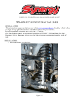
15. Install the passenger side sway bar end link onto the upper hole in the side of the Synergy front track
bar bracket. If using the factory nut and bolt, torque the nut and bolt to 59lb-ft. If using the Synergy
disconnect pin, torque the pin nut to 80lb-ft. See Figure 12.
Figure 12. Sway Bar Link Installed on Bracket
16. Installation is now complete. Check bolt torques after approximately 100 miles.
Table 1. Vehicle Bolt Torques
Bolted Joint Location
Wrench Size
Torque
Lug Nuts
21mm (OEM)
125lb-ft
M14-2.00 bolts, all
22mm
125lb-ft
1/2-13 x 3.0” bolt
3/4"
80lb-ft
Sway Bar End Link Bolts to Axle
18mm (OEM)
59lb-ft
Synergy Sway Bar Disconnect Studs
3/4"
80lb-ft
/