Page is loading ...

28 1
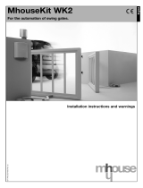
ATTENTION:
Do not use the equipment
without rst reading the
instruction manual.
Technical manual
P30460 - 03/2022
Rev. 0
Manufactured by: Motoppar Indústria e Comércio de Automatizadores Ltda
Av. Dr. Labieno da Costa Machado, 3526 - Distrito Industrial - Garça - SP - CEP 17406-200 - Brasil
CNPJ: 52.605.821/0001-55
www.ppa.com.br | +55 14 3407 1000
LIGER UNIVERSAL

2 3
CONTENTS
Important Safety Instructions ...............................................................................................3
How to lift the operator .........................................................................................................4
Technical Features ...............................................................................................................4
Basic tools needed for installation .......................................................................................5
Electrical connections ..........................................................................................................5
Precautions with the gate before installation ........................................................................6
Installing and mounting the operator ...................................................................................6
Assembling the wheel ............................................................................................... 8
Mounting the operator ...............................................................................................8
Installing the photocell .......................................................................................................10
Configuration of the jumpers ...................................................................................11
Indication of the LEDs ............................................................................................. 11
Photocell precautions .............................................................................................11
Troubleshooting ..................................................................................................................12
Facility Top Control Board ..................................................................................................12
Electrical connections ............................................................................................. 13
Programming Index Chart .......................................................................................14
'SN' LED functions ..................................................................................................15
Electric lock input ....................................................................................................15
Functions of '+' and '-' buttons ................................................................................15
Adding remote controls ...........................................................................................16
Erasing all remote controls ......................................................................................16
Strength (Force - Electronic clutch) ........................................................................16
Automatic memorization of the opening / closing time (Analog limit switch) or travel
(Digital limit switch) .................................................................................................17
Automatic / Semi-automatic mode .......................................................................... 17
Selecting the application type ................................................................................18
Selecting the type of the limit switch (Analog or digital) ......................................... 19
Selecting the delay time ..........................................................................................20
Brake activation time ...............................................................................................21
Courtesy light time ..................................................................................................21
Traffic light (Exit annunciator) time .......................................................................... 21
Factory default settings ...........................................................................................22
Enabling or disabling a reversion command ..........................................................23
Soft start .................................................................................................................. 23
Torque control strength (Close limit switch area) .................................................... 23
Torque control strength (Open limit switch area) ....................................................24
Torque control strength on closing cycle (Memorization) .......................................24
Torque control strength on opening cycle (Memorization) .....................................24
Limit of the area of the close limit switch ................................................................25
Limit of the area of the open limit switch ................................................................. 25
Adjustment of the position of the closing limit switch (CLS) ...................................25
Adjustment of the position of the open limit switch (OLS) ......................................26
Enabling or disabling a command on opening cycle .............................................26
IMPORTANT SAFETY INSTRUCTIONS
Recommendation:
When installing the operator, the PPA’s specialist installer must comply
with all the instructions present on both this TECHNICAL MANUAL and
the USER MANUAL.
By using the USER MANUAL, the installer must present all information,
uses and security items of the device to the end-user.
Prior to installing LIGER UNIVERSAL, carefully read and observe the
instructions contained herein.
-Prior to installing the operator, ensure that the local grid power complies
with the technical data appearing on the gate operator’s label;
-Do not connect the operator to the source of power until the installation
/ maintenance (or servicing) is over. Proceed the wiring of the control
unit with the control box power switched OFF;
-Do not change the voltage jumper! The voltage selection jumper is to
the exclusive use of the manufacturer; the installer must respect the
voltage appearing on the gate operator’s label;
-After installing the operator, make sure the gate system is placed far
enough from the sidewalk;
-The system’s power supply network MUST include a disconnection
device (not supplied).
NOTE: This product is manufactured with the M6 straight grease fitting that
allows for easy greasing of the internal crown, as the gearmotor does not need
to be disassembled for maintenance to be carried out, providing speed and
convenience for installers.

4 5
PARANETERS AND TECHNICAL FEATURES
TYPE OF OPERATOR SLIDING SLIDING
POWER SUPPLY 220 V 220 V
RATED FREQUENCY 60 Hz 50 Hz
RATED POWER 265 W 265 W
RPM 1740 1740
RATED CURRENT 1.3 A 1.3 A
REDUCTION RATIO 1:40 1:40
LINEAR SPEED 9.8 m/min 9.8 m/min
CYCLES / HOUR 60 60
PROTECTION CLASS IPX 4 IPX 4
TEMPERATURE RANGE
-5°C
+50 °C
-5°C
+50 °C
INSULATION SYSTEM Class B, 130 ° C Class B, 130 ° C
LIMIT SWITCH SYSTEM HYBRID HYBRID
TECHNICAL FEATURES
BASIC TOOLS NEEDED FOR INSTALLATION
Tools needed:
ELECTRICAL CONNECTIONS
For the electrical set-up, the power grid must have the following features:
- 127 V / 220 V Power Supply;
- 5A Circuit Breakers in the Electrical Panel;
- 3/4” diameter conduits between the electrical panel and the disconnection
device;
- 3/4” diameter conduits between the disconnection device and the outlet;
- 1/2” diameter conduits for (optional) external pushbuttons;
- 1/2” diameter conduits for photocells (required).
IMPORTANT
The operator must be powered through a Differential Residual
(DR) Current device with a Nominal residual operating current not
exceeding 30 mA.
LINEMAN’S
PLIERS HACKSAW HEX NUT DRIVER SCREWDRIVER OPEN-END
WRENCH
STEPLADDER
WELDING MACHINE HAMMER SPIRIT LEVEL TAPE MEASURE
TRY SQUARE ELECTRIC DRILL PENCIL ELECTRIC SANDER /
HAND GRINDER
HOW TO LIFT THE OPERATOR
(ABOVE 20 KG - ~44 LB)
One can lift the operator by means of ropes or straps
and lift hooks. Follow the procedure below:
Step 1: Tie the ropes / straps according to the picture
to the right.
Step 2: Lift the operator slowly, assuring that the product
is balanced and properly tied.
Step 3: Lower the operator slowly and put it on a safe
place.

6 7
PRECAUTIONS WITH THE GATE BEFORE THE
INSTALLATION
- Before proceeding with the product’s installation, make sure that the structure of
the gate is suitable for being automated.
- It is very important to check the distance between the gate and the ground,
i.e., the slope of the ground along its course, taking as reference the gate's hinge.
'Liger Universal' compensates slopes up to 300 mm (~1 ft). The distance between
the gate and the ground cannot be more than 250mm (9.9 in), since it corresponds
to the maximum displacement of the operator.
Note: If such conditions cannot be met, the structure of the gate must be improved
in order for it to work properly.
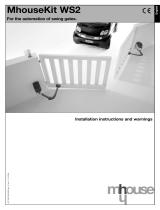
INSTALLING AND MOUNTING THE OPERATOR
Before proceeding with the product’s installation, disconnect any
unnecessary cables as well as any devices or systems from the mains
power supply.
250 mm
300 mm
PORTÃO
553 mm
443 mm 415 mm
In order to install the operator, observe the slope of the ground, since it is very
important to the operation and durability of the pieces which are part of the
mechanical assembly.
Step 1: On the left leaf of the gate, install the operator with the wheel mounted to
its right. On the right leaf of the gate, install the operator with the wheel mounted
to its left. See the picture below. By doing this, the housing will not skid against
the ground.
Step 2: In order to protect the wheel from early wear and tear, it is necessary to
lean the operator according to the picture below.
OBSERVE DE DENTRO PARA FORA DO IMÓVEL
FOLHA ESQUERDA
RODA FIXADA
NO LADO DIREITO
DO AUTOMATIZADOR
FOLHA DIREITA
RODA FIXADA
NO LADO ESQUERDO
DO AUTOMATIZADOR
SENTIDO DE ABERTURA
VISTA SUPERIOR
FOLHA ESQUERDA FOLHA DIREITA
G AT E
250 mm
(~9.9 in)
300 mm (~1 ft)
OBSERVE FROM INSIDE THE HOUSE
LEFT LEAF
LEFT LEAF
SUPERIOR VIEW
OPENING DIRECTION
WHEEL MOUNTED TO
THE RIGHT OF THE
OPERATOR
WHEEL MOUNTED
TO THE LEFT OF THE
OPERATOR
RIGHT LEAF
RIGHT LEAF
553 mm (~1.9 ft)
443 mm (~1.5 ft) 415 mm (~1.4 ft)

8 9
ASSEMBLING THE WHEEL
The wheel can be mounted on either side of the operator.
In order to do so, follow the procedures below:
Step 1: Remove the housing of the operator.
Step 2: By means of a 6-mm Allen wrench, loosen the fastening screw until it
comes out.
Step 3: Pull the wheel. It will go out easily.
Step 4: Mount the wheel again, on the desired side, and fit the housing.
Step 5: The wheel which is touching the ground must be placed inwards the
operator.
MOUNTING THE OPERATOR
Step 1: Place the equipment 3 to 4 meters (~9.9 to 13.2 ft) from the gate's hinge,
according to the picture below.
3A4METROS
CHAVE ALLEN 6mm
Step 2: Weld a metal sheet (270 x 370 mm / ~10.7 x 14.6 in), whose fastening
position will depend on the slope on the ground; screw the operator's plate
(fastening base) on this sheet. In case there is no slope, place the operator in
such a way that its articulations remain parallel to the ground.
Step 3: Mount the stopper on the column and its arm on the gate's leaf. Afterwards,
adjust the opening and closing, removing the protection housing and adjusting the
micro-switch system, according to the picture below.
It is required to screw the housing by means of six 3.9 x 10 screws
before using the operator.
370 mm
270 mm
CHAPADE
FIXAÇÃO
DA MÁQUINA
SISTEMA DE FIM DE CURSO
CARENAGEM DO
PROTEÇÃO
COLUNA DO PORTÃO
PORTÃO
6mm ALLEN WRENCH
3 TO 4 METERS (~10 TO 13.2 FT)
270 mm
(~10.7 in)
OPERATOR PLATE
(FASTENING BASE)
LIMIT SWITCH (STOPPER)
PROTECTION
HOUSING
G AT E
GATE’S COLUMN
370 mm (~1.3 ft)

10 11
INSTALLING THE PHOTOCELL
Step 1: Attach both transmitter and receiver units, aligned between them, at a
minimum 30 cm from the ground, in such a way that the hole of the housing (where
the cables pass through), faces downwards, in order to avoid water dripping
inside the product.
15 A20 Vcc
15A20 Vcc
ENTRADA DE
FOTOCÉLULA
DO AUTOMATIZADOR
PLACA
RECEPTORA 1
PLACA
RECEPTORA 2
PLACA
TRANSMISSORA 1
PLACA
TRANSMISSORA 2
ENTRADA DE FOTOCÉLULA
DO AUTOMATIZADOR
+Vcc
GND
Step 2: Connect 15 up to 20
Vdc to the transmitter board,
respecting the polarity of the
‘+ -’ terminal block.
Step 3: Connect 15 up to 20 Vdc to the
receiver board, respecting the polarity of the
‘+ -’ terminal block. The output port of the
terminal block (‘OUT’) must be connected to
the photocell input port on the operator.
Note: More than one photocell can be connected to the operator in a cascade
connection. In such configuration, connect the ‘OUT’ output of the second photocell
to the ‘AUX’ output of the first photocell; the ‘OUT’ output of the first photocell must
be connected to the photocell input port on the operator.
This way, one can use as many photocells as necessary, with the condition that
the ‘AUX’ jumper must be closed on the boards that receive the signal from other
photocell. All photocells must be powered by a power supply. In this kind of
installation, in order to avoid security issues on the system, care must be taken to
ensure that there is not interference from a beam of a photocell to another. In such
installation, in case the beam of a photocell is blocked, the operator recognizes an
obstruction on the system and will interrupt its operation.
CONFIGURATION OF THE JUMPERS
ALIN: When this jumper is closed, the photocell does not keep the output active
if the beam is blocked, making the alignment easier during the installation. This
jumper must remain open during normal operation of the system.
AUX: If the photocell is receiving a signal from other photocell (in a cascade
connection), this jumper must be closed so that it acknowledges (recognizes) the
signal received from other photocell.
AJUSTE: When this jumper is closed, it decreases the sensitivity of the photocell
so that it can be used on environments where false triggerings might occur.
MODO: It changes the photocell output signal. When this jumper is open, the
output is either NO or NC. When it is closed, the output is pulsed.
Note: PPA operators must use a 'Pulse' output.
NA/NF: If the 'MODO' jumper is open, it sets the output signal as: open jumper
set as NO (Normally Open) and closed jumper set as NC (Normally Closed). If the
'MODO' jumper is closed, the 'NA/NF' jumper has no function.
INDICATION OF THE LEDS
‘SN’ LED (green) on and ‘AUX’ LED (red) off: photocell with no obstruction and
‘AUX’ output not used.
‘SN’ LED on and ‘AUX’ LED on: photocell with no obstruction and ‘AUX’ output
active with no obstruction.
Both ‘SN’ LED and ‘AUX’ LED flashing: ‘AUX’ output active, but with obstruction.
‘SN’ LED flashing and ‘AUX’ LED off: photocell with obstruction and ‘AUX’ output
not used.
‘SN’ LED flashing and ‘AUX’ LED on: photocell with obstruction and ‘AUX’ output
active with no obstruction.
PHOTOCELL PRECAUTIONS
- Avoid installing the receiver directly facing the Sun;
- Make sure the side where the wiring orifice is faces down;
- Install the photocell away from obstacles which could block the beam;
- Install the photocell 30 cm (~1 ft) from the ground;
- If the distance between the receiver photocell and the transmitter photocell is
less than 5 meters (~16.5 ft), when installed over a smooth floor (surfaces with a
high light reflection), the reflection of the ground or walls might affect the proper
operation of the sensors.
15 TO 20 VDC 15 TO 20 VDC
PHOTOCELL INPUT
PORT
PHOTOCELL INPUT PORT
RECEIVER
BOARD 1
RECEIVER
BOARD 2
TRANSMITTER
BOARD 2
TRANSMITTER
BOARD 1

12 13
TROUBLESHOOTING
The table below contains useful information on some PROBLEMS — SYMPTOMS,
PROBABLE CAUSES AND POSSIBLE SOLUTIONS which might affect your
operator. Before intervening on the system (maintenance, cleaning), always
disconnect the product from the mains power supply.
FACILITY TOP CONTROL BOARD
MAIN FEATURES
- It can be used with either digital limit switch (encoder hall) or magnetic limit
switch (analog).
- RF 433.92 Mhz Receiver Module.
- Code learning – up to 160 different and button-independent remote controls.
SYMPTOMS PROBABLE CAUSE(S) ACTION(S)
Manouver fails
to start
A) No power supply
B) Open / Blown fuse
C) Gate jammed
D) Defective limit switch
A) Ensure that the power cable is
correctly inserted in the power outlet.
B) Substitute the fuse for another one
with the same specifications
C) Ensure there are no obstruction on
the gate travel
D) Substitute the analog limit switch
system
Motor won't run A) Reversed wiring
B) Gate or operator jammed
A) Check the wiring
B) Change to manual mode and
check it separately
Control board
does not accept
a command
A) Blown fuse
B) No power supply
C) Defective remote control /
Low battery
D) Remote control range
A) Substitute the fuse for another
B) Ensure that the power cable is
correctly inserted in the power outlet
C) Check and substitute the battery
D) Check the position of the
receiver's antenna and, if necessary,
try adjusting it, if you think the signals
to be weak
Motor only runs
in one direction
A) Reversed wiring
B) Reversed limit switch
system
C) Defective control board
A) Check the motor wiring
B) Reverse the limit switch connector
(analog and/or digital)
C) Substitute the control board
- Input ports:
- Photocell.
- Loose RF Receiver Module.
- RS-485 Serial Module.
- Output ports:
- Traffic Light (Visual Exit Annunciator) Module.
- Electric lock module.
- Courtesy light module.
- Control of the motor:
- Soft start.
- Electronic clutch.
- Electronic brake.
- Torque control.
ELECTRICAL CONNECTIONS
AMARELO
PRETO/VERMELHO
VERMELHO / PRETO
MOTORDE
INDUÇÃO
MONOFÁSICO
127 VAC
220 VAC
(50 Hz/60 Hz)
FIMDE CURSO
DIGITAL
JUMPER
SELETOR DE
TENSÃO
AUTOMATIZADOR
COM FIMDE CURSO
FCA
FCF
ACF
BOTÕES
PARA AJUSTES
DAS FUNÇÕES
CHAVES DIP SWITCH
PARA SELECIONAR
AS FUNÇÕES
RECEPTOR RF
433,92 MHz
HRF
FECHAD
O=HABILITA RF
ABERT
O=DESABILITA RF
CAPACITOR
DE PARTIDA
DO MOTOR
MÓDULO
RELÉ
PARA TRAVA
MÓDULO
RELÉ PARA
LUZDE GARAGEM
MÓDULO
RELÉ PARA
SINALEIRO
RECEPTOR
AVULSO
IR
TX
FOTOCÉLULA
12V 12V
GND GND
NA
NA
RX
OPERATOR WITH
LIMIT SWITCH
DIGITAL LIMIT
SWITCH
VOLTAGE
SELECTION
JUMPER
127 VAC 220 VAC
(50 HZ / 60 HZ) RED / BLACK
BLACK / RED
SINGLE-PHASE
INDUCTION
MOTOR
ENGINE
STARTING
CAPACITOR
PHOTOCELL
RELAY
MODULE FOR
ELECTRIC
LOCK
RELAY MODULE FOR
COURTESY LIGHT
LOOSE
RECEIVER
DIP SWITCH FOR
CHOOSING THE
FUNCTIONS
FUNCTION-ADJUSTING
BUTTONS
CLOSED = ENABLES RF
OPEN = DISABLES RF
RF 433.92 MHZ
RECEIVER
RELAY
MODULE
FOR TRAFFIC
LIGHT
12V
GND
NO
NO
YELLOW

14 15
PROGRAMMING INDEX CHART
Lever Function ‘+’ Button '–' Button
8 Adds remote controls Adds
8 Erases remote controls 2nd Confirms 1st Erases
8+1 Enables or disables direction reversion
through a command (Pushbutton and
remote control) Enables Disables
8+2 Enables or disables a command on
opening cycle (Pushbutton and remote
control) Enables Disables
7 Strength (Electronic clutch) + Strength – Strength
7+4 Torque control strength on the close
limit switch area (Memorization) + Torque – Torque
7+3 Torque control strength on the open
limit switch area (Memorization) + Torque – Torque
7+2 Torque control strength on the close
limit switch area + Torque – Torque
7+1 Torque control strength on the open
limit switch area + Torque – Torque
6Memorization (Digital limit switch) or
opening / closing time (Analog limit
switch)
Starts memo-
rizing
6+4 Setback adjustment of the close limit
switch (difference between the gate
and the stopper)
Larger set-
back Lesser set-
back
6+3 Setback adjustment of the open limit
switch (difference between the gate
and the stopper)
Larger set-
back Lesser set-
back
6+2 Limit of the close limit switch area Larger space Lesser space
6+1 Limit of the open limit switch area Larger space Lesser space
5Automatic or semi-automatic mode
(hold the button pressed for the
desired time)
Pause time
(automatic) Semi-auto-
matic
5+4 Electronic brake activation time + Brake – Brake
5+3 Soft start time (120 milliseconds per
pulse) Longer Shorter
5+2 Traffic light (Exit annunciator) time (50
milliseconds per pulse) Longer Shorter
5+1 Courtesy light time (10 seconds per
pulse) Longer Shorter
Lever Function ‘+’ Button '–' Button
4
Selects sliding application Once
Selects swing application Twice
Selects double swing application with
an opening delay 3 times
Selects double swing application with
a closing delay 3 times
3 Selects digital or analog limit switch Digital Analog
2Closing delay time (Hold the button
pressed for the desired time) Delay time Without delay
1 Factory default settings (default/ reset) Default
‘SN’ LED FUNCTIONS
- Flashes once (60-Hz power source).
- Flashes twice (50-Hz power source).
- Flashes normally* 3 times (Opening cycle).
- Flashes normally* 4 times (Closing cycle).
- Flashes inversely** 3 times (Opening cycle with encoder failure).
- Flashes inversely** 4 times (Closing cycle with encoder failure).
- Flashes normally* 5 times (Gate travel (path) reset).
- Flashes in ‘clock mode’ every one second (counting the time for automatic
closing).
- Continuously lit (photocell input activated).
ELECTRIC LOCK INPUT
The control board will enable or disable the electromagnetic lock automatically
when a relay module is connected or disconnected to the ‘TRV’ connector. An
electromagnetic lock installation results in a 1-second delay on the opening
command. The electric lock activation time is 3 seconds.
FUNCTIONS OF '+' AND '-' BUTTONS
- In access operations, i.e., when the levers of the DIP Switch are off, they are used
as opening / closing commands.
* Flashes normally: LED normally off, goes on for 100 milliseconds. This cycle repeats itself every 2 seconds.
** Flashes inversely: LED normally on, goes off for 100 milliseconds. This cycle repeats itself every 2 seconds.

16 17
- When programming the control board (any lever(s) of the DIP Switch on) or
adding a remote control, they are used as an input to the memory update.
IMPORTANT: The levers described on the instructions are the levers from the DIP
Switch.
ADDING REMOTE CONTROLS
Code learning - up to 160 remote controls, regardless from the fact that either one
button or two buttons per remote control have been added.
Step 1: The gate must be still and must not be counting the pause time for
automatic closing.
Step 2: Turn the lever 8 on.
Step 3: Press the button of the remote control one wants to add and hold it pressed.
Step 4: ‘SN’ LED must flash rapidly.
Step 5: Press and release the ‘+’ button.
Step 6: Check the ‘SN’ LED: If it flashes once, the button has been successfully
added; if it flashes twice, the button is already added to the memory.
Step 7: Release the button of the remote control.
Step 8: In order to add other remote control, go back to step 3.
Step 9: In order to finish, turn the lever 8 off.
ERASING ALL REMOTE CONTROLS
Step 1: The gate must be still and must not be counting the pause time for
automatic closing.
Step 2: Turn the lever 8 on.
Step 3: Press and release the ‘–’ button.
Step 4: The ‘SN’ LED lights up.
Step 5: Press and release the the ‘+’ button to confirm the exclusion of all remote
controls (the ‘SN’ LED flashes four times) or press and release the ‘–’ button to
cancel the exclusion process.
Step 6: In order to finish, turn the lever 8 off.
STRENGTH (FORCE - ELECTRONIC CLUTCH)
Step 1: This adjustment can be performed with the gate either moving or still.
Step 2: Turn the lever 7 on.
Step 3: ‘SN’ LED turns itself off.
Step 4: Use the ‘+’ and ‘–’ buttons to increase or decrease the strength.
Step 5: Check the ‘SN’ LED:
- Flashes rapidly = adjustment between the minimum and the maximum.
- Flashes slowly = adjustment on the minimum or the maximum.
The variations of the adjustment levels are:
60 Hz = 0 up to 13 pulses.
50 Hz = 0 up to 17 pulses.
Step 6: In order to finish, turn the lever 7 off.
AUTOMATIC MEMORIZATION OF THE OPENING / CLOSING TIME
(ANALOG LIMIT SWITCH) OR TRAVEL (DIGITAL LIMIT SWITCH)
Step 1: The gate must be still.
Step 2: Turn the lever 6 on.
Step 3: ‘SN’ LED remains off.
Step 4: Press and release the ‘+’ button. The motor will be activated for the closing
cycle up to the Closing Limit switch. After one second, the motor will be activated
for the opening cycle, memorizing the travel (path) through the opening / closing
time (analog limit switch) or through the pulses of the digital encoder up to the
closing limit switch (analog limit switch). Three seconds are added to the opening
and closing time (analog limit switch).
Step 5: In order to finish, turn the lever 6 off.
Step 6: In order to perform a new memorization (acquiring, self-learning) go back
to step 2.
WARNING:
The remote control can be used to cancel and restart the memorization
process. During the memorization, one can cancel the process by
turning the lever 6 off or through a remote control command.
AUTOMATIC / SEMI-AUTOMATIC MODE
Step 1: The control board must not be counting the time for an automatic closing
(pause time).
Step 2: Turn the lever 5 on.
Step 3: ‘SN’ LED remains off.
Step 4: Set the closing mode, as follows:
SETTING AUTOMATIC MODE (PAUSE TIME):
Step 5: Press and hold the ‘+’ button.
Step 6: SN LED starts operating in ‘clock mode’.
Step 7: Count the desired time interval through the ‘SN’ LED.

18 19
WARNING:
The maximum time interval is 255 seconds (4.25 minutes). During the
time counting, when it reaches the 255-second limit time, the counting
is reset to 1 second.
Step 8: Release the ‘+’ button.
Step 9: ‘SN’ LED stops operating in ‘clock mode’.
Step 10: In order to add a new pause time, go back to step 5.
Step 11: In order to set it in semi-automatic mode, go to step 13.
Step 12: In order to finish, turn the lever 5 off.
SEMI-AUTOMATIC MODE:
Step 13: Press the ‘–’ button.
Step 14: ‘SN’ LED flashes for 2 seconds.
Step 15: In order to set it in automatic mode, go back to step 5.
Step 16: In order to finish, turn the lever 5 off.
SELECTING THE APPLICATION TYPE
Step 1: The gate must be still.
Step 2: Turn the lever 4 on.
Step 3: ‘SN’ LED remains off.
Step 4: Choose the type of application:
Sliding = Press the ‘+’ button once.
Vertical Swing = Press the ‘+’ button twice.
Master swing RETA = Press '+' button 3 times.
Master swing RETF = Press '–' button 3 times.
WARNING :
When using the 'Master Swing RETA (Opening)' or 'Master Swing
RETF (Closing)' modes, all settings will be performed through the
Master Control Board without the need of performing any adjustment
on the Slave Control Board.
Whenever the '+' or '–' buttons are pressed, the 'SN' LED flashes
rapidly.
Step 5: Wait three seconds.
Step 6: If the ‘SN’ LED flashes rapidly, the application is valid. If it flashes slowly,
the application is invalid.
Step 7: In order to choose a new application, go back to step 4.
Step 8: In order to finish, turn lever 4 off.
Step 9: The ‘SN’ LED will keep flashing 5 times, indicating that the travel (path) is
reset (digital limit switch).
WARNING:
Whenever a new application is chosen, the opening / closing time is
reset to the 4-minute default factory setting (analog limit switch) or the
travel (path) is reset (digital limit switch).
For applications with a digital limit switch, in order to have a proper
operation, a new memorization is required.
SELECTING THE TYPE OF THE LIMIT SWITCH
(ANALOG OR DIGITAL)
Step 1: The gate must be still.
Step 2: Turn the lever 3 on.
Step 3: ‘SN’ LED remains off.
Step 4: Choose the type of limit switch:
Digital limit switch = ‘+’ button.
Analog limit switch = ‘–’ button.
WARNING:
The ‘SN’ LED rapidly flashes for the selected option.
Step 5: In order to change the type of limit switch, go back to step 4.
Step 6: In order to finish, turn the lever 3 off.
Step 7: The ‘SN’ LED will keep flashing 5 times, indicating that the travel (path) is
reset (digital limit switch).
WARNING:
Whenever a new type of limit switch is chosen, the opening / closing
time is reset to the 4-minute default factory setting (analog limit switch)
or the travel (path) is reset (digital limit switch). For applications with
a digital limit switch, in order to have a proper operation, a new
memorization is required.

20 21
SELECTING THE DELAY TIME
Step 1: The gate must be still and the control board must not be counting the time
for an automatic closing (pause time).
Step 2: The control board must be set for swing applications.
Step 3: Turn the lever 2 on.
Step 4: ‘SN’ LED remains off.
Step 5: Choose the 'with delay' / 'without delay' mode according to the instructions:
WITH DELAY:
Step 6: Press the '+' button and hold it pressed.
Step 7: The 'clock mode' is activated ('SN' LED flashes every second).
Step 8: Count the desired time by means of the 'SN' LED.
WARNING:
The maximum time interval is 255 seconds (4.25 minutes). During the
time counting, when it reaches the 255-second limit time, the counting
is reset to 1 second.
Step 9: Release the '+' button.
Step 10: The 'Clock mode' is deactivated.
Step 11: In order to set a new delay time, go back to step 6.
Step 12: In order to program without delay, go to step 14.
Step 13: In order to finish, turn the lever 2 off.
WITHOUT DELAY:
Step 14: Press the '–' button.
Step 15: 'SN' LED flashes for 2 seconds.
Step 16: In order to program with delay, go to step 6.
Step 17: In order to finish, turn the lever 2 off.
WARNING:
When the delay time is set on opening, the delay is fixed in one
second. During the closing cycle, when the gate RETA reaches the
stopper (CLS), the closing delay time is cancelled and the gate RETF
starts closing.
BRAKE ACTIVATION TIME
Step 1: Turn the levers 5 and 4 on.
Step 2: ‘SN’ LED remains off.
Step 3: Use the ‘+’ and ‘–’ buttons to increase or decrease the time.
Step 4: Check the SN LED:
Flashes rapidly = adjustment between the minimum and the maximum.
Flashes slowly = adjustment on the minimum or the maximum.
Levels: 0 to 12
0 = brake disabled.
1 = 200 milliseconds.
12 = 2.4 seconds.
Step 5: In order to finish, turn the levers 5 and 4 off.
WARNING:
When the 'swing' mode and and digital limit switch are used, it starts
operating in a different manner: after detecting the stopper, the control
board forces the motor against the stopper in order to assure a proper
closure. The higher the brake adjustment, the higher the pressure of
the operator against the stopper.
COURTESY LIGHT TIME
Step 1: Turn the levers 5 and 1 on.
Step 2: ‘SN’ LED remains off.
Step 3: Use the ‘+’ and ‘–’ buttons to increase or decrease the time.
Step 4: Check the ‘SN’ LED:
Flashes rapidly = adjustment between the minimum and the maximum.
Flashes slowly = adjustment on the minimum or the maximum.
Levels: 0 to 24
0 = does not count the time, it switches off immediately after the gate
reaches the closing limit switch.
1 = 10 seconds.
24 = 240 seconds (4 minutes).
Step 5: In order to finish, turn the levers 5 and 1 off.
TRAFFIC LIGHT (EXIT ANNUNCIATOR) TIME
Step 1: Turn the levers 5 and 2 on.
Step 2: ‘SN’ LED remains off.
Step 3: Use the ‘+’ and ‘–’ buttons to increase or decrease the time.
Step 4: Check the ‘SN’ LED:
Flashes rapidly = adjustment between the minimum and the maximum.
Flashes slowly = adjustment on the minimum or the maximum.

22 23
Levels: 0 to 20
0 = continuous mode.
1 = oscillating mode (50 milliseconds).
20 = oscillating mode (1000 milliseconds).
Step 5: In order to finish, turn the levers 5 and 2 off.
FACTORY DEFAULT SETTINGS
Step 1: The gate must be still.
Step 2: Turn lever 1 on.
Step 3: ‘SN’ LED remains off.
Step 4: Press and release the ‘+’ button.
Step 5: ‘SN’ LED rapidly flashes once.
Step 6: In order to finish, turn the lever 1 off.
Step 7: The LED keeps flashing 5 times, indicating that the memorized travel
(path) is reset (Digital limit switch).
WARNING:
After resetting it to the default factory setting, if the operator uses
a digital limit switch system (encoder sensor hall), a new acquiring
(memorization, self-learning) is necessary for a proper operation.
Default factory settings:
Strength = maximum.
Soft start = disabled.
Semi-automatic mode.
Opening / Closing time = 4 minutes.
Brake strength = level 1.
Brake activation time= 400 milliseconds.
Courtesy light time = 60 seconds.
Traffic light (Exit annunciator) = continuous.
Limit switch = digital.
Accepts a command on opening = enabled.
Movement reversion through a command = enabled.
Strength of torque control on opening = level 5.
Strength of torque control on closing = level 5.
Strength of torque control on opening (memorization) = level 9.
Strength of torque control when closing (memorization) = level 9.
Limit of opening limit switch = travel (path) – 16 pulses.
Limit of opening limit switch = travel (path) – 16 pulses.
FCF (CLS - Closing limit switch) adjustment = 0-pulse setback (recoil,
backlash).
FCA (OLS - Opening limit switch) adjustment = 0-pulse setback (recoil,
backlash).
ENABLING OR DISABLING A REVERSION COMMAND
Step 1: Turn the levers 8 and 1 on.
Step 2: 'SN' LED remains off.
Step 3: ‘+’ Button = Enables reversion command.
Step 4: 'SN' LED rapidly flashes once.
Step 5: ‘–’ Button = Disables reversion command.
Step 6: 'SN' LED rapidly flashes once.
Step 7: In order to finish, turn the levers 8 and 1 off.
SOFT START
Step 1: Turn the levers 5 and 3 on.
Step 2: ‘SN’ LED remains off.
Step 3: Use the ‘+’ and ‘–’ buttons to increase or decrease the time.
Step 4: Check the ‘SN’ LED:
Flashes rapidly = adjustment between the minimum and the maximum.
Flashes slowly = adjustment on the minimum or the maximum.
Levels: 0 to 30
60 Hz:
0 = Soft start disabled (motor starts with network rated voltage).
1 = Soft start enabled (120 milliseconds).
30 = Soft start enabled (3.6 seconds).
50 Hz:
0 = Soft start disabled (motor starts with network rated voltage).
1 = Soft start enabled (160 milliseconds).
30 = Soft start enabled (4.8 seconds).
Step 5: In order to finish, turn the levers 5 and 3 off.
TORQUE CONTROL STRENGTH
(CLOSE LIMIT SWITCH AREA)
Step 1: Turn levers the 7 and 2 on.
Step 2: ‘SN’ LED remains off.
Step 3: Use the ‘+’ and ‘–’ buttons to increase or decrease the torque control
strength.
Step 4: Check the ‘SN’ LED:
Flashes rapidly = adjustment between the minimum and the maximum.
Flashes slowly = adjustment on the minimum or the maximum.
Levels: 0 (weak) to 30 (strong)
Step 5: In order to finish, turn the levers 7 and 2 off.

24 25
TORQUE CONTROL STRENGTH
(OPEN LIMIT SWITCH AREA)
Step 1: Turn the levers 7 and 1 on.
Step 2: ‘SN’ LED remains off.
Step 3: Use the ‘+’ and ‘–’ buttons to increase or decrease the torque control
strength.
Step 4: Check the ‘SN’ LED:
Flashes rapidly = adjustment between the minimum and the maximum.
Flashes slowly = adjustment on the minimum or the maximum.
Levels: 0 (weak) to 30 (strong)
Step 5: In order to finish, turn the levers 7 and 1 off.
TORQUE CONTROL STRENGTH ON CLOSING CYCLE
(MEMORIZATION)
Step 1: Turn the levers 7 and 4 on.
Step 2: ‘SN’ LED remains off.
Step 3: Use the ‘+’ and ‘–’ buttons to increase or decrease the torque control
strength.
Step 4: Check the ‘SN’ LED:
Flashes rapidly = adjustment between the minimum and the maximum.
Flashes slowly = adjustment on the minimum or the maximum.
Levels: 0 (weak) to 30 (strong)
Step 5: In order to finish, turn the levers 7 and 4 off.
TORQUE CONTROL STRENGTH ON OPENING CYCLE
(MEMORIZATION)
Step 1: Turn the levers 7 and 3 on.
Step 2: ‘SN’ LED remains off.
Step 3: Use the ‘+’ and ‘–’ buttons to increase or decrease the torque control
strength.
Step 4: Check the ‘SN’ LED:
Flashes rapidly = adjustment between the minimum and the maximum.
Flashes slowly = adjustment on the minimum or the maximum.
Levels: 0 (weak) to 30 (strong)
Step 5: In order to finish, turn the levers 7 and 3 off.
LIMIT OF THE AREA OF THE CLOSE LIMIT SWITCH
It is the distance between the closing mechanical stop plate and the point on the
travel where the control board enters the torque control mode to decrease the
speed of the gate and turn it off, when it is on the 0 (zero) position.
Step 1: Turn the levers 6 and 2 on.
Step 2: ‘SN’ LED remains off.
Step 3: Use the ‘+’ and ‘–’ buttons to increase or decrease the limit.
Step 4: Check the 'SN' LED:
Flashes rapidly = adjustment between the minimum and the maximum.
Flashes slowly = adjustment on the minimum or the maximum.
Levels: 0 to 50
Step 5: In order to finish, turn the levers 6 and 2 off.
LIMIT OF THE AREA OF THE OPEN LIMIT SWITCH
It is the distance between the opening mechanical stop plate and the point on
the travel where the control board enters the torque control mode to decrease the
speed of the gate and turn it off on the memorized travel.
Step 1: Turn the levers 6 and 1 on.
Step 2: ‘SN’ LED remains off.
Step 3: Use the ‘+’ and ‘–’ buttons to increase or decrease the limit.
Step 4: Check the ‘SN’ LED:
Flashes rapidly = adjustment between the minimum and the maximum.
Flashes slowly = adjustment on the minimum or the maximum.
Levels: 0 to 50
Step 5: In order to finish, turn the levers 6 and 1 off.
ADJUSTMENT OF THE POSITION OF THE CLOSE LIMIT SWITCH
(CLS)
It is the adjustment of the setback (1 pulse) or of the advance (1 pulse) of the close
limit switch.
Step 1: Turn the levers 6 and 4 on.
Step 2: ‘SN’ LED remains off.
Step 3: Use the ‘+’ and ‘–’ buttons to increase or decrease the limit switch position.
Step 4: Check the 'SN' LED:
Flashes rapidly = adjustment between the minimum and the maximum.
Flashes slowly = adjustment on the minimum or the maximum.
Levels: 0 to 50
Step 5: In order to finish, turn the levers 6 and 4 off.

26 27
ADJUSTMENT OF THE POSITION OF THE OPEN LIMIT SWITCH (OLS)
It is the adjustment of the setback (1 pulse) or of the advance (1 pulse) of the
opening limit switch.
Step 1: Turn the levers 6 and 3 on.
Step 2: ‘SN’ LED remains off.
Step 3: Use the ‘+’ and ‘–’ buttons to increase or decrease the limit switch position.
Step 4: Check the 'SN' LED:
Flashes rapidly = adjustment between the minimum and the maximum.
Flashes slowly = adjustment on the minimum or the maximum.
Levels: 0 to 50
Step 5: In order to finish, turn the levers 6 and 3 off.
ENABLING OR DISABLING A COMMAND ON OPENING CYCLE
Step 1: Turn the levers 8 and 2 on.
Step 2: 'SN' LED remains off.
Step 3: ‘+’ Button = Enables command on opening.
Step 4: 'SN' LED rapidly flashes.
Step 5: Botão (–) = Disables command on opening.
Step 6: 'SN' LED rapidly flashes.
Step 7: In order to finish, turn the levers 8 and 2 off.
/