Page is loading ...

Yellow
Black
3
VANDAL PROOF CAMERA
2
AF Zoom Dome
5
VANDAL PROOF CAMERA
4
AF Zoom Dome
6
AF Zoom Dome
7
VANDAL PROOF CAMERA
11
VANDAL PROOF CAMERA
10
AF Zoom Dome
9
VANDAL PROOF CAMERA
8
AF Zoom Dome
13
VANDAL PROOF CAMERA
12
AF Zoom Dome
15
VANDAL PROOF CAMERA
14
AF Zoom Dome
CAUTION!
TO REDUCE THE RISK OF ELECTRIC SHOCK,
DO NOT REMOVE COVER (OR BACK).
NO USER-SERVICEABLE PARTS INSIDE.
REFER SERVICING TO QUALIFIED
SERVICE PERSONNEL.
CAUTION
RISK OF ELECTRIC SHOCK
DO NOT OPEN
Explanation of two Symbols
The lightning flash with arrowhead symbol,
within an equilateral triangle, is intended to
alert the user to the presence of un-insulated
"dangerous voltage" within the product's
The exclamation point within an equilateral
triangle is intended to alert the user to the
presence of important operating and
maintenance-(servicing) instructions in the
THE GRAPHIC SYMBOLS WITH SUPPLEMENTAL MARKING ARE
ON THE BOTTOM OF THE SYSTEM.
"WARNING-TO PREVENT FIRE OR SHOCK HAZARD, DO NOT
EXPOSE THE UNIT TO RAIN OR MOISTURE"
enclosure that may be of sufficient magnitude to constitute a
risk of electric shock to persons.
literature accompanying the appliance.
OWNER'S MANUAL
VANDAL PROOF DOME CAMERA
P/N : 3810-0049C
(Ver.0607E)
Color Dome Camera Series
AF Zoom Dome Camera Series
Auto Focus
Zoom Dome Camera
Auto Focus
Zoom Dome Camera
Design and specifications
are subject to
change without notice.
19
VANDAL PROOF CAMERA
18
AF Zoom Dome
17
VANDAL PROOF CAMERA
16
AF Zoom Dome
21
VANDAL PROOF CAMERA
20
AF Zoom Dome
22
AF Zoom Dome
23
VANDAL PROOF CAMERA
30
AF Zoom Dome
31
VANDAL PROOF CAMERA
38
AF Zoom Dome
39
VANDAL PROOF CAMERA
28
AF Zoom Dome
29
VANDAL PROOF CAMERA
36
AF Zoom Dome
37
VANDAL PROOF CAMERA
26
AF Zoom Dome
27
VANDAL PROOF CAMERA
34
AF Zoom Dome
35
VANDAL PROOF CAMERA
24
AF Zoom Dome
25
VANDAL PROOF CAMERA
32
AF Zoom Dome
33
VANDAL PROOF CAMERA
44
AF Zoom Dome
45
VANDAL PROOF CAMERA
42
AF Zoom Dome
43
VANDAL PROOF CAMERA
40
AF Zoom Dome
41
VANDAL PROOF CAMERA
5. Name and Functions
7. Remote Controller Operation
Receiver
Remote Control
1 2 3 4
Power
DC 12V, 500mA
RS-485 Signal
- White Terminal :
- Black Terminal :
Camera Selection
- After camera connects with receiver,
firstly check camera I.D.
Menu
(
PROG
)
: Shows / Hides Menu.
Moves up and down items.
(
TELE
)
:
(
WIDE
)
:
- Press camera I.D. number(1
~
39 buttons)
on the top of wireless remote controller.
Caution : Usually camera I.D. number
are selected from No.1 to No.39.
over I.D. No.40, you will have a use limit.
- Initial camera I.D. number is set up No.0
when it takes out of manufacturer's warehouse.
Example: ZOOM IN
I.D. No.5: Press 5 +
<
TELE
>
I.D. No.15: Press
<F1>
+ 5 +
<
TELE
>
I.D. No.24: Press
<F2>
+ 4 +
<
TELE
>
I.D. No.34: Press
<F3>
+ 4 +
<
TELE
>
Set data for the selected items.
(
NEAR
)
:
(
FAR
)
:
F1
NEAR
FAR
FOCUS
F3
WIDE
F2
TELE
ZOOM
AUTO
SEQ PAN
PROG
A
7
4
1
6
9
A
0
8
5
32
Option
2. UTP (Unshielded Twisted Pair)
The remote controller is optional item.
9. On-Screen Display
-
16x, 22x Series
8. Communication Protocol
10. Menu Format
-
16x, 22x Series 11. Menu Format Table
-
16x, 22x Series
. Contents
3. Camera Installation
6. Installation
1. Connecting to Monitor and Power
#
1
#
2
No.
#1
#2
Function
Video Output
Power Input
Remark
1.0 Vp-p
AC24V(20V~28V)orDC12V(11V~15V), Max 6W/ 0.5A
Terminal Color
Yellow
Green
No.
#1
#2
Function
Video Output
Power Input
Remark
1.0 Vp-p
DV12V(DC9V~15V), Max 5.4W/ 450mA
Terminal Color
Yellow
Red
#
1
#
2
- The wire is polarized.
- Use AC 24V power source or DC 12V power source.
- Connect the video out jack to the video in jack of monitor.
- Connect the power adapter to the power input connecter.
- Use DC 12V power source.
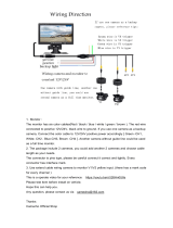
For AC 24V / DC 12V Power Type (Normal)
Connecting to Power
Connecting to Controller
Connecting to Monitor
For DC 12V Power Type
Cable Connection
Monitor
Remote Control
Receiver
Vandal Proof
Zoom Dome Camera
Signal (RS-485)
Built
-
in
Digital Zoom
192x Zoom
192x Zoom
220x Zoom
220x Zoom
260x Zoom
260x Zoom
• Built-in Optical Power Zoom Lens
This camera with highly durable built-in zoom lens offers auto focus,
auto iris, and optical zoom functions enabling the user to monitor a
scene with clarity in any desired angle of view.
• High Resolution & Sensitivity SONY CCD
The chassis features a highly sensitive 1/4 inch CCD pick-up with
approximately 380,000(NTSC), 440,000(PAL) effective pixels
minimizing residual image and geometric distortion.
• Camera Rotation in Variable Angle
Camera assembly part is designed as round from, so it is easy to
rotate in variable angle. Don't mind the position of camera at the
time of installation.
• Remote Control through RS-485 (Pelco-D)
Remote control operations are possible though RS-485 interface for
focus and zoom control. In addition, the unit lets you command
white balance and exposure manually using RS-485 interface.
• Digital Slow Shutter for full color surveillance under very low
light condition : 0.001 Lux (at 128x Field)
• Excellent Interior Decoration
Dome body made by aluminum is resistant to impact.
Servicing
Do not attempt to disassemble or repair by yourself.
You may be exposed to dangerous voltage or other hazards.
Note that all servicing is qualified service personnel.
Modifications not approved by manufacturer could void the user's
authority to operate the equipment.
Power Sources
To prevent electric shocks and risk of hazards, do NOT use
more than the specified power source.
Install on an Unstable Place
Do not place or install this camera on an unstable place, stand,
tripod, bracket or table. That may cause serious injury to people
or damage appliance.
Environment
Do not install too warm or too cold place.
Recommended operation temperature is between -10 C and 50 C.
Heavy Shock and Vibration
Do not drop the dome camera or subject it to heavy shock of
vibration.
Note
When this camera is installed near equipment,
like a wireless communication device that emits a strong electro
magnetic field, some irregularity such as noise on the monitor
screen may happen.
Sunlight
Do not point the camera at the sun. CCD can be damaged.
Day & Night Model
• Day & Night Function : 0.1 Lux
Day & Night Model
16x Zoom (Optical: 16x, Digital: 12x)
22x Zoom (Optical: 22X, Digital: 10x)
26x Zoom (Optical: 26X, Digital: 10x)
1. Model Description
4. Composition
2. Precautions 3. Features
On-Screen Display
OSD
OSD
Upside
Downside
Camera Assembly
Camera Control Key
(Arrow Direction)
Housing Base
T :
W :
N :
F :
M :
V :
Tele(Zoom In)
Wide(Zoom Out)
Near(Focus Control)
Far(Focus Control)
Menu(Menu On)
Video Out Jack
Camera Control
(RS-485 Communication)
Power Input
(Be careful its polarity)
Composite Video Output BNC
Camera Control
Setup Key
Service Video
Out Jack
Video
(Yellow)
Power - DC 12V
(Red)
Video
(Yellow)
Power - AC 24V/ DC 12V
(Green)
Video Output
GND
Video Output
GND
- When using AC 24V power, it is possible to supply the power within 100m.
- Use 4 wires by 2 pair of wires.
- When using DC 12V power, UTP wire can not be used for power line.
- Connect UTP (Unshielded Twisted Pair) wire to the UTP output of the
camera directly.
UTP transmitter is included in the camera therefore additional UTP
transmitter is not necessary.
- UTP receiver is necessary to connect UTP wire to Monitor or DVR.
- When connecting UTP wire, make sure the polarity of the video signal.
- Use UTP wire "CAT5 24AWG" to have the best transmission quality.
- The twisted-pair output cannot be used at the same time as the Composite
Video output.
Yellow
Black
Monitor(or DVR)
300m(Max)
UTP Cable
UTP Receiver
AC 24V
Power Supply
100m(Max)
2 Wire
Yellow
Black
Receiver &
Remote Control
Pelco-D Keyboard
DVR System
RS-485
Power OnFunction
MSG
BYTE 1
0xFF
BYTE 2
CamID
BYTE 3
0x88
BYTE 4
0x00
BYTE 5
0x00
BYTE 6
0x00
BYTE 7
Checksum
Power OffFunction
MSG
BYTE 1
0xFF
BYTE 2
CamID
BYTE 3
0x08
BYTE 4
0x00
BYTE 5
0x00
BYTE 6
0x00
BYTE 7
Checksum
Pelco D StopFunction
MSG
BYTE 1
0xFF
BYTE 2
CamID
BYTE 3
0x00
BYTE 4
0x00
BYTE 5 BYTE 6 BYTE 7
Checksum
Menu On / OffFunction
MSG
BYTE 1
0xFF
BYTE 2
CamID
BYTE 3
0x40
BYTE 4
0x00
BYTE 5
0x00
BYTE 6
0x00
BYTE 7
Checksum
Focus FarFunction
MSG
BYTE 1
0xFF
BYTE 2
CamID
BYTE 3
0x00
BYTE 4
0x80
BYTE 5
0x00
BYTE 6
0x00
BYTE 7
Checksum
Focus NearFunction
MSG
BYTE 1
0xFF
BYTE 2
CamID
BYTE 3
0x01
BYTE 4
0x00
BYTE 5
0x00
BYTE 6
0x00
BYTE 7
Checksum
Zoom WideFunction
MSG
BYTE 1
0xFF
BYTE 2
CamID
BYTE 3
0x00
BYTE 4
0x40
BYTE 5
0x00
BYTE 6
0x00
BYTE 7
Checksum
Zoom TeleFunction
MSG
BYTE 1
0xFF
BYTE 2
CamID
BYTE 3
0x00
BYTE 4
0x20
BYTE 5
0x00
BYTE 6
0x00
BYTE 7
Checksum
PELCO "D" Byte Format
Command Message
-RS-485,2400bps,1 Start bit,8 data bits,1 stop bit,no parity
Menu On / OffFunction
MSG
BYTE 1
0xFF
BYTE 2
CamID
BYTE 3
0x00
BYTE 4
0x23
BYTE 5
0x00
BYTE 6
0x5F
BYTE 7
Checksum
Menu On / OffFunction
MSG
BYTE 1
0xFF
BYTE 2
CamID
BYTE 3
0x00
BYTE 4
0x03
BYTE 5
0x00
BYTE 6
0x62
BYTE 7
Checksum
Pelco Keyboard (95+ PATTERN)
V/D Keyboard (Set Preset + 98)
Don't care
Explanation of the On-Screen Display
The OSD (On Screen Display) is as follows:
X10000 ID 255
WAIT
X132
1 2 3 4 5 6
7
8
4. WBC(White Balance Control) Display
See Page 20.
6. Camera ID Display
See Page 20.
5. Shutter Speed
Use to select the shutter speed.
7. Wait Mode
Indicates the camera stand-by mode
until the camera power turns on.
8. Example of Zoom, Brightness,
Sharpness Display
See Page 20.
2. Mirror
When IMAGE MIRROR is ON state. The
image is displayed in the opposite direction.
The appear during the mirror mode.
1. Focus
The appear during the focus manual
mode.
3. Back light Display
In case the excessive light is behind the
center object, it is necessary to prevent
the center object from too much
darkness. Turn the BACK LIGHT ON,
then the center object is not influenced
by the back light.
FUNCTION OSD Format DESCRIPTION
1
2
3
4
Focus Mode
Mirror Mode
Back Light
WBC Mode
5
Shutter
Speed
Non display
Non display
Non display
Non display
Normal shutter (NTSC:1/60 PAL:1/50)
8 variable.
7
Wait Mode
Wait
Indicates the camera stand-by mode.
until the camera power turns ON.
8.1
Sharpness
Adjustment
Mode Display
8.2
Brightness
Adjustment
Mode Display
8
Zoom
Display
x16
:
Optical Zoom only mode
x32
:
Digital Zoom x 2 mode
x192
:
Digital Zoom x 12 mode
6
Camera ID
After input the identification number to each camera,
Multi-point control is available. (000~255)
Automatic focus mode
Manual focus mode
No screen inverted
Screen is inverted to the left or right
Back Light compensation off
Back Light compensation mode
White Balance AUTO
Push Auto White Balance: In this mode
"Menu key" pressed, the white point traced
automatically (PWB Auto Mode), "Menu Key"
released, the white point preserved currently
(PWB Manual Mode).
Non display
1 / 125
1 / 10000
x18
x10
SHP
/
TELE / WIDE
MENU
Move up and down
using the TELE/
WIDE button.
1 BACKLIGHT
2 NEG / POS
3 COLOR
4 WB CONTROL
5 SHUTTER
6 CAMERA
OFF
POS
ON
AUTO
1/10000
123
MENU
7 ZOOM START
8 ZOOM STOP
9 BRIGHTNESS
10 SHARPNESS
11 FOCUS
12 PROTOCOL
13 INIT SET
END
1
192
48
10
AUTO
P/D
ON
Can be changed
using the /
button.
1. General Model
MENU
1 BACKLIGHT
2 SLOW SHUTTER
3 DAY / NIGHT
4 WB CONTROL
5 SHUTTER
6 CAMERA
OFF
FLD24
OFF
AUTO
1/10000
123
MENU
7 ZOOM START
8 ZOOM STOP
9 BRIGHTNESS
10 SHARPNESS
11 FOCUS
12 PROTOCOL
13 INIT SET
END
1
192
48
10
AUTO
DEF
ON
2. Day & Night Model
NO
NAME FUNCTION
1 BACKLIGHT
Use to select BLC mode.
OFF >ON
2 NEG / POS
Use to change NEGATIVE and POSITIVE mode.
ON : NEGATIVE mode OFF : POSITIVE mode
5 SHUTTER
Use to select the shutter speed 8 steps.
NORMAL(NTSC:1/60, PAL:1/50),1/125,1/250,---,1/10000
7 ZOOM START
Use to change the zoom start position.
8 ZOOM STOP
Use to change the zoom stop position.
9 BRIGHTNESS
Use to change the brightness of scene (0~48).
10 SHARPNESS
Use to change the contour of scene (0~15).
11 FOCUS
. AUTO : Set the focus mode to Auto mode.
. PUSH AUTO : Set the focus mode to Push Auto mode.
12 PROTOCOL
. DEF : Default
. P / D : Pelco-D
13 INIT SET
Set the initial mode ON, the changed data are renewed.
Reset the data to its shipping condition.
6 CAMERA ID
To connect a large number of camera, identification
number can be assigned to each camera control easily.
(OFF, 1-255 : total number of ID is 256)
CAUTION : Set the ID number of camera, then
the ID number is displayed continuously.
3 COLOR
Use the change color and monochrome of picture.
ON : Color mode OFF : Black and White mode
4 WB CONTROL
. AUTO : Maintain best color condition by controlling
the change of color automatically.
WB Range 2800 K ~ 8000 K
.
PUSH AUTO(PWB) :
Can find White Balance exactly
in case precise WB maintenance
is needed under any environment.
--Turn the AUTO mode, WB acts automatically.
--Turn the PUSH AUTO mode, WB doesn't act.
: Day & Night Model
SLOW SHUTTER
Use under very low light condition for full color
surveillance.
OFF >FLD2 > >FLD128
DAY & NIGHT
Use under low light condition for continuous
surveillance.
Auto >ON >OFF
46
AF Zoom Dome
47
VANDAL PROOF CAMERA
15. Specifications
-
26x Series
16. Troubleshooting
If there is no picture on the monitor screen,
make sure all the cables are properly connected.
make sure the monitor is properly adjusted.
DO NOT DISASSEMBLE THE CAMERA
IF ANY DEFECTIVE CAMERA HAS BEEN OPENED BEFORE IT
ARRIVES TO AUTHORIZED RMA OFFICE, THE DEFECTIVE CAMERA
MAY NOT BE REPAIRED UNDER IT'S WARRANTY SERVICE.
If the picture on the monitor screen is not clear,
clean the lens.
adjust the lens focus.
If there is a video noise or other unknown problems,
stop using the camera and call your local dealer.
14. Specifications
-
16x, 22x Series
Signal System
Signal System
Scanning System
Scanning Frequency(H)
Scanning Frequency(V)
Image Sensor
Effective Pixels Number
S/N Ratio
Resolution
Video Output Level
Lens
Digital Zoom Ratio
Min. Shooting Distance
Min. Illumination
Sync. System
OSD(On Screen Display)
Shutter Speed (8 Steps)
Input/ Output Connector
Power Consumption
(Option: AC24V/DC12V)
Dimensions
Weight
NTSC PAL
525 Lines 625 Lines
2 : 1 Interlace
15.734 kHz 15.625 kHz
59.94 Hz 50Hz
1/4 inch SONY IT CCD
768(H) x 494(V)[Normal:510(H) x 492(V)] 752(H) x 582(V)[Normal:500(H) x 582(V)]
More than 48dB (AGC Off)
Horizontal : 480 TV Lines [Normal : 380 TV Lines]
1.0 Vp-p (75 Ohms, composite)
16x (F1.4, f=3.9~62.4mm)/ 22x
(
F1.6,f=3.9~85.8mm
)
12x (Total Zoom Ratio: 192x)/ 10x
(
Total Zoom Ratio: 220x
)
1 cm (Wide) / 1 meter (Tele)
1.0 Lux (30 IRE), 0.001 Lux (Day & Night Model)
Internal
On / Off
1/60 ~ 1/10,000 Sec. 1/50 ~ 1/10,000 Sec.
Control: 5 Pin Terminal, Power: 2 Pin Terminal, Video: BNC
DC 12V (DC 9V
~
15V), Max. 5.4W / 450mA
AC 24V (20V
~
28V) or DC 12V (11V
~
15V), Max 6W/ 0.5A
119.8mm (Dome Diameter) x 126.5 (Height)
Approx. 1600g
Model Description
Precautions
Features
Composition
Name and Functions
Installation
Remote Controller Operation
Communication Protocol
1.
2.
3.
4.
5.
6.
7.
8.
5
6
7
8
9
11
15
17
On-Screen Display
Menu Format
Menu Format Table
Specifications
9.
10.
11.
14.
18
20
21
45
Troubleshooting16. 47
1. AF Zoom
Dome Camera .................
2. Screw (4ea) .....................................................
3. Service Monitor Cable ....................................
4. L-Wrench ......................
5. Guide Pattern .................
6. Owner's Manual .........................
O
W
N
E
R
'
S M
A
N
U
A
L
V
A
NDA
L
PRO
O
F
D
O
ME
C
A
ME
RA
Auto F
ocus
Zoo
m
D
om
e
Cam
e
r
a
Auto F
ocus
Zoo
m
D
om
e
Cam
e
r
a
B
ui
lt
-
in
1
9
2
x
Z
o
o
m
1
9
2
x
Z
o
o
m
2
2
0
x
Z
o
o
m
2
2
0
x
Z
o
o
m
Di
g
i
t
a
l
Z
o
o
m
2
6
0
x
Z
o
o
m
2
6
0
x
Z
o
o
m
O
n
-
S
c
r
e
e
n
D
is
p
la
y
OSD
OSD
INFORMATION
This equipment has been tested and found to comply with limits for a
Class A digital device, pursuant to part 15 of the FCC Rules.
These limits are designed to provide reasonable protection against
harmful interference when the equipment is operated in a commercial
environment.
This equipment generates, uses, and can radiate radio frequency energy
and, if not installed and used in accordance with the instruction manual,
may cause harmful interference to radio communications.
Operation of this equipment in a residential area is likely to cause
harmful interference in which case the user will be required to correct
the interference at their own expense.
WARNING
The manufacturer could void the user's authority to operate the
equipment.
CAUTION - To prevent electric shock and risk of fire hazards:
Do NOT use power sources except for that specified.
Do NOT expose this appliance to rain or moisture.
This installation should be made by a qualified service person
and should abide to all local codes.
Camera Control Key
Functions can be setup using 5 buttons
on the camera's housing base.
Tele (Zoom In)
Moves up and down on OSD menu
Wide (Zoom Out)
Moves up and down on OSD menu
Near (Focus Control)
Set data for the selected on OSD menu
Far (Focus Control)
Set data for the selected on OSD menu
Menu (Menu On/ Off)
Shows/Hides Menu
T
W
N
F
M
..........................................
..........................................
..........................................
..........................................
..........................................
Service Video Out Jack
Use for installation and service.
V
Dome Cover
Stick the guide pattern on
the wall / ceiling.
Drill four holes according
to the guide pattern then
insert anchors into the
drilled holes.
Draw out power / video
wires to the connecting
places.
Fix the housing base by
screws on the ceiling.
Adjust desired focus and
scene by turning and moving
the hemisphere by hand.
Put the dome cover over
the base.
Fix the dome cover on the
base by L-Wrench.
Ceiling
16 x
Series
22 x
Series
Type
Digital
Zoom
Day &
Night
UTP Power InputDSS
Model
26 x
Series
Before operating the camera, confirm that you have the right
camera model and proper power voltage.
In order to help you understand this manual, we'll introduce
our model's description.
Thank you for purchasing this COLOR VIDEO CAMERA.
192 x
192 x
192 x
192 x
192 x
192 x
220 x
220 x
220 x
220 x
220 x
220 x
260 x
260 x
260 x
X
O
X
O
X
O
X
O
X
O
X
O
O
O
O
DC 12V
DC 12V
AC 24V / DC 12V
AC 24V / DC 12V
AC 240V / DC IN
AC 240V / DC IN
DC 12V
DC 12V
AC 24V / DC 12V
AC 24V / DC 12V
AC 240V / DC IN
AC 240V / DC IN
DC 12V
AC 24V / DC 12V
AC 24V / DC 12V
X
X
X
X
O
O
X
X
X
X
O
O
X
X
O
X
O
X
O
X
O
X
O
X
O
X
O
X
X
X
A
B
C
D
E
F
A
B
C
D
E
F
A
B
C
260x
zoom
16x
/
22x
zoom
260x
zoom
16x
/
22x
zoom
16x
/
22x
zoom
260x
zoom
16x
/
22x
zoom
260x
zoom
16x
/
22x
zoom
260x
zoom
16x
/
22x
zoom
260x
zoom
16x
/
22x
zoom
16x
/
22x
zoom
16x
/
22x
zoom
260x
zoom
260x
zoom
260x
zoom
260x
zoom
260x
zoom
260x
zoom
260x
zoom
260x
zoom
260x
zoom
260x
zoom
260x
zoom
260x
zoom
260x
zoom
260x
zoom
16x
/
22x
zoom
ND: No Display
FUNCTION
OSD
EXPLANATION
4
White
Balance
6
Shutter
Speed
8
Motion
Detect
9
Initial
LOGO
10
Zone
Label
5
Pan / Tilt
7
ID
11
Zoom
ND
ND
ND
x125
~
x10000
000
~
255
x1
...
Dx260
F.
L
ND
MD
WAIT
-
Automatic color correction mode
Special color correction mode
Indoor mode
Outdoor mode
Temporary automatic mode
No Act Digital Panning / Tilting
Digital Panning / Tilting
Standard shutter speed (NTSC:1/60, PAL:1/50)
Flicker correction mode
Shutter speed indicator
Camera identification number
No motion detected
Motion detected
Displayed when POWER ON of the
camera is in operation
Explanation of the scene capture
by the camera (max. 10 letters)
Optical zoom: x1
~
x26
Digital zoom: Dx27
~
Dx260
* 'D' indicates digital zoom
SwB
IwB
OwB
PwB
Explanation of the On-Screen Display
The OSD (On Screen Display) is as follows:
X10000 255
WAIT
Dx260
1 2 3 4 5 6 7
9
8
Zone Label
11
MD
10
12. On-Screen Display
-
26x Series
ND: No Display
FUNCTION
OSD
EXPLANATION
1
Focus
2
Mirror
3
Backlight
ND
ND
ND
Automatic focus mode
Manual focus mode
No screen inverted
Screen is inverted to the left or right
Backlight compensation off
Backlight compensation mode
Automatic backlight compensation mode
13. Menus and Operations
-
26x Series
PALNTSCSignal System
Scanning System
Effective Pixels No
Image Sensor
Resolution
Sync. System
S/N Ratio
Lens
Minimum Illumination
AGC
White Balance
Flickerless
Backlight Control
Day & Night Level Control
Video Output
Power Consumption
(Option: DC 12V)
Dimensions
Weight
2 : 1 Interlace
768(H) x 494(V) 752(H) x 582(V)
1/4 Inch SONY Super HAD CCD
480 TV lines
Internal
More than 48dB (AGC off)
26x Zoom Video AF
(F1.6(W), F3.8(T) f= 3.5~91.0mm)
Normal mode: Typical 1 Lux at 30IRE (AGC on)
Auto
Auto
On / Off Selectable
On / Off Selectable
Volume Adjustment
VBS 1.0Vp-p 75
AC 24V/DC 12V Model: AC 24V± 20%, DC 12V± 20%, 15W (Max)
DC 12V Model: DC 12V± 10%, 10W (Max)
119.8mm (Dome Diameter) x 126.5 (Height)
Approx. 1600g
16x, 22x
On-Screen Display
Menus and Operations
Specifications
12.
13.
15.
22
24
46
...................................
.............................................
..................................................
............................................
...............................
...............................................
.................
........................
..................................
...........................................
.................................
..........................................
......................................
..................................
...........................
..........................................
26x
2. Press the TELE/WIDE button.
3. Press the NEAR/FAR button.
4. Press the OSD MENU button at the main menu or sub-menu screen
to hide the menu.
It moves up and down the main menu category.
The sub-menu functions of the main menu category are displayed on the right.
It moves to the sub-menu window of the selected main menu.
The current set state of each sub-menu can be checked.
Press the TELE/WIDE button to move up and down the sub-menu category
and set each category by pressing the NEAR/FAR button.
It does not apply when the MENU button is used for other uses.
: 'Zone Label' setup screen
WIDE
MENU
FOCUS MODE
PUSH AUTO
FOCAL DIST
ZOOM START
ZOOM END
GENERAL
FOCUS
AWB
AE
D&N
BLC
MOTION
DISPLAY
INITIAL
EXIT
TELE / WIDE
FOCUS
FOCUS MODE
PUSH AUTO
FOCAL DIST
ZOOM START
ZOOM END
INITIAL
EXIT
Can be changed
using the
Near/Far button.
MANUAL
OFF
1CM
x001
x260
OFF
Edits and displays the information of camera or explanation on the area of the
image being captured at the bottom left of the screen.
Maximum of 10 letters can be used/ edited.
It is described in detail on page 44.
2. LANGUAGE
Displays the currently set language.
Language can be set from ENG to KOR and vice versa using the NEAR/FAR button.
3. ZONE LABEL
4. COLOR
5. SHARPNESS
6. MIRROR
7. PROTOCOL
8. INITIAL
9. EXIT
Selects color or black and white mode.
Adjusts sharpness of outlines.
Can be set from 0 to 15.
P/D : Pelco-D
DEF : Default
Resets the current general settings category to the initial settings.
Inverts the screen to the right or left.
Closes the sub-menu and moves to the main menu.
Caution
Change the data of the sub-menu using the NEAR/FAR button.
Sets up the general operation of the camera.
Press the NEAR/FAR button to move to the sub-menu.
Main Menu- GENERAL
1. CAMERA ID
Displays the camera's ID.
Camera ID can be specified using numbers from 000 to 255 by using
the NEAR/FAR button.
GENERAL
CAMERA ID
LANGUAGE
ZONE LABEL
COLOR
SHARPNESS
MIRROR
PROTOCOL
INITIAL
EXIT
Can be changed
using the
Near/Far button.
001
ENG
EDIT
ON
10
OFF
DEF
OFF
Move up and
down using the
TELE/WIDE button.
NEAR / FAR
NEAR / FAR
MENU
CAMERA ID
LANGUAGE
ZONE LABEL
COLOR
SHARPNESS
MIRROR
PROTOCOL
GENERAL
FOCUS
AWB
AE
D&N
BLC
MOTION
DISPLAY
INITIAL
EXIT
- DEF
(Default)
- P/D
(Pelco-D)
Minimum distance the camera can focus.
ex) 60 cm: Objects/subjects closer than 60 cm cannot be brought into focus.
2. PUSH AUTO
When temporary automatic focus is selected, the camera focuses
automatically when only the NEAR/FAR button is pressed.
In the Automatic Mode, it will be displayed as "Not Used".
3. FOCAL DIST
4. ZOOM START
5. ZOOM END
6. INITIAL
7. EXIT
Minimum zoom movement.
Possible from x 001 to x 260
Maximum zoom movement.
Possible from x 001 to x 260
Closes the sub-menu and moves to the main menu.
Initializes the changed category in focus menu.
Note) Automatic focus in manual mode is only possible when the location of the zoom
lens has changed or when the "temporary automatic focus" category is selected.
Automatic focus is also possible based on external AF command (1 shot AF).
Sets camera zoom and focus.
Press the NEAR/FAR button to move to the sub-menu.
Main Menu- FOCUS
1. FOCUS MODE
AUTO: Focuses automatically when changes are made to the screen.
MANUAL: User focuses manually.
NEAR / FAR
MENU
FOCUS MODE
PUSH AUTO
FOCAL DIST
ZOOM START
ZOOM END
GENERAL
FOCUS
AWB
AE
D&N
BLC
MOTION
DISPLAY
INITIAL
EXIT
FOCUS
FOCUS MODE
PUSH AUTO
FOCAL DIST
ZOOM START
ZOOM END
INITIAL
EXIT
MANUAL
OFF
50CM
x001
x260
OFF
5. INITIAL
6. EXIT
Closes the sub-menu and moves to the main menu.
Initializes the changed category in AWB menu.
1. AWB
AUTO : Automatically adjusts color according to the available lighting.
PUSH AUTO : Color will be automatically adjusted while the NEAR/FAR button
is pressed in the temporary automatic mode.
INDOOR : Set color temperature to be 3200K.
OUTDOOR : Set color temperature to be 5400K.
SPECIAL : Color can be corrected when the user increases or decreases
"Red Correction" or "Blue Correction".
2. RED CONT
Can be changed in special mode only, and R-Gain value is adjusted.
Can be set from 0 to 255.
3. BLUE CONT
Can be changed in special mode only, and B-Gain value is adjusted.
Can be set from 0 to 255.
4. PUSH AUTO
Can be used in temporary automatic mode only.
Color will be automatically adjusted while the NEAR/FAR button is pressed at
temporary automatic mode. (the word "Pressed" will be displayed.)
Adjusts picture color.
Press the NEAR/FAR button to move to the sub-menu.
Main Menu- AWB
AWB
WB MODE
RED CONT
BLUE CONT
PUSH AUTO
INITIAL
EXIT
AUTO
NOT USED
NOT USED
NOT USED
OFF
NEAR / FAR
MENU
WB MODE
RED CONT
BLUE CONT
PUSH AUTO
GENERAL
FOCUS
AWB
AE
D&N
BLC
MOTION
DISPLAY
INITIAL
EXIT
2. BRIGHTNESS
Brightness can be adjusted from 0 (dark) to 48 (bright).
Can be used while in manual mode.
4. SHUTTER SPD
Can be changed while in manual and shutter manual mode.
Shutter speed can be changed from standard to 1/10000.
Standard shutter speed: NTSC- 1/60, PAL- 1/50.
5. IRIS ADJUST
Adjusts the opening of iris.
Can be adjusted from 0 (closed) to 255 (opened).
Change in screen can be recognized only within the certain range.
Can be adjusted while in manual and gain adjustment mode.
6. AGC ADJUST
Gain adjustment of image signal.
Can be adjusted from 0 to 255.
Can be adjusted while in manual and gain adjustment mode.
3. FLICKERLESS
Removes screen flickering caused by discordance of frequency and lighting.
7. AGC MAX SET
Maximum gain value used when gain is automatic.
Can be adjusted from 0 to 255.
8. INITIAL
Initializes the changed category in exposure menu to the initial settings.
9. EXIT
Closes the sub-menu and moves to the main menu.
1. AE MODE
AUTO : Automatically adjusts brightness according to the available lighting.
MANUAL : Manually adjusts all brightness.
AGC MAN : Allows you to adjust gain.
IRIS MAN : Allows you to adjust iris.
SHUT MAN : Allows you to adjust the shutter speed.
Adjusts picture brightness.
Press the NEAR/FAR button to move to the sub-menu.
Main Menu- AE
AE
AE MODE
BRIGHTNESS
FLICKERLESS
SHUTTER SPD
IRIS ADJUST
AGC ADJUST
AGC MAX SET
INITIAL
EXIT
AUTO
33
OFF
NOT USED
NOT USED
NOT USED
213
OFF
NEAR / FAR
MENU
AE MODE
BRIGHTNESS
FLICKERLESS
SHUTTER SPD
IRIS ADJUST
AGC ADJUST
AGC MAX SET
GENERAL
FOCUS
AWB
AE
D&N
BLC
MOTION
DISPLAY
INITIAL
EXIT
Determines and operates in mode suitable for day or night.
Press the NEAR/FAR button to move to the sub-menu.
Main Menu- D & N
1. D&N MODE
AUTO : Filter operates automatically according to brightness.
NIGHT : Manual Mode- removes IR cut filter.
DAY : Manual Mode- does not remove IR cut filter.
NEAR / FAR
MENU
D&N MODE
BRT LEVEL
FILTER DLY
IR LED
D&N CDS/AE
GENERAL
FOCUS
AWB
AE
D&N
BLC
MOTION
DISPLAY
INITIAL
EXIT
D&N
D&N MODE
BRT LEVEL
FILTER DLY
IR LED
D&N CDS/AE
INITIAL
EXIT
- CDS
- AE
AUTO
48
10 SEC
SET
CDS
OFF
3. FILTER DLY
Sets conversion time of IR cut filter while in automatic mode.
Time can be adjusted from 0 to 60 seconds.
2. BRT LEVEL
Sets brightness that determines the opening/closing or IR cut filter while in
Automatic Mode.
Screen brightness can be adjusted
• CDS: 1 (bright) to 170 (dark) Default: 48 (20 Lux)
• AE: 1 (bright) to 118 (dark) Default: 90 (20 Lux)
Please set up the level higher when you install this camera into the housing.
4. IR LED
Determines whether IR LED light will be on/off at night.
• SET: uses built-in IR LED in night state
• UNSET: does not use built-in IR LED in night state
5. INITIAL
Initializes the changed category in Day/Night Menu.
6. EXIT
Closes the sub-menu and moves to the main menu.
•
While IR LED is on mode make sure to select D&N CDS/AE to „CDS ”.
⇒
⇒
Note) BLC (Backlight Correction): Function that sharpens subjects only.
1. BLC MODE
Sharpens subjects with backlight.
OFF : Backlight Correction function is disabled.
ON : Backlight Correction function is enabled.
AUTO : Backlight Correction function is enabled automatically.
2. BLC LEVEL
Sets sensitivity to backlight.
Can be adjusted from 0 to 40.
3. INITIAL
Initializes the changed category in backlight menu.
4. EXIT
Closes the sub-menu and moves to the main menu.
Caution
It may not function properly when shutter speed is not 'standard'.
Function that sharpens outlines of subjects and background when
there is strong backlight.
Press the NEAR/FAR button to move to the sub-menu.
Main Menu- BLC
BLC
BACK LIGHT
BLC LEVEL
INITIAL
EXIT
OFF
16
OFF
MENU
NEAR / FAR
BACK LIGHT
BLC LEVEL
GENERAL
FOCUS
AWB
AE
D&N
BLC
MOTION
DISPLAY
INITIAL
EXIT
1. DETECT MODE
Enables or disables motion detection function.
2. DETECT AREA
Sets motion detection field.
Can be set to UPPER, LOWER, RIGHT, LEFT, CENTER and WHOLE.
When there is movement of the subject in the screen, there will be an
alarm, or the user will be informed through communications or "MD"
will display on the screen.
Press the NEAR/FAR button to move to the sub-menu.
Main Menu- MOTION
Note) There is a signal every time there is movement by the subject. If motion is
detected, MD (Motion Detected) is displayed on the upper left of the screen.
This message enables the user to set On-screen display state in the menu.
Note) The detection field on screen is as follows:
3. SENSITIVITY
Sets sensitivity to detect movement.
Can be set from 1 (low response) to 15 (sensitive).
5. INITIAL
Initializes the changed category in motion detection menu.
6. EXIT
Closes the sub-menu and moves to the main menu.
4. OUTPUT MODE (For RS-422 Model)
Informs detection when motion has been detected.
ALARM : Sends alarm using the output line connected to outside.
COMM : Communication packet is transmitted when motion is detected.
ALARM/COMM : Uses communications packet and external output line
simultaneously.
Caution
Error can occur in the motion detection function in the following cases.
(1) When lighting is unsteady.
(2) When light changes often even though there is no movement of the subject.
It is recommended that this function should be used after setting the detection
sensitivity and detection field after monitoring the environment for an extended time.
CENTER
LOWER
UPPER
WHOLE
LEFT RIGHT
MENU
NEAR / FAR
DETECT MODE
DETECT AREA
SENSITIVITY
OUTPUT MODE
GENERAL
FOCUS
AWB
AE
D&N
BLC
MOTION
DISPLAY
INITIAL
EXIT
MOTION
DETECT MODE
DETECT AREA
SENSITIVITY
OUTPUT MODE
INITIAL
EXIT
OFF
WHOLE
8
ALARM/COMM
OFF
Note) Refer to the "On-Screen Display" for details.
1. WHOLE OSD
All on-screen display is "ON" or "OFF".
Nothing will be displayed if specified as "Hidden" even when other categories
are individually set as "ON". (Exception: Initial logo when power is turned on.)
5. ZOOM MAG
Displays zoom on lower right of the screen.
The number in Dx260 shows the magnification, and D represents digital zoom.
2. FUNC OSD
Images displayed on the upper area of the screen.
Refer to the "On-Screen Display" section- images 1 to 6.
3. MOTION DET
"MD" is displayed on the upper left of the screen when motion is detected.
4. CAMERA ID
Displays ID number on the upper right of the screen.
6. ZONE LABEL
Displays texts explaining screen area on the lower left of the screen.
7. VERSION
Displays the version information of camera (cannot be changed).
8. INITIAL
Initializes the changed category in On-screen display menu.
9. EXIT
Closes the sub-menu and moves to the main menu.
Specity what to display on the screen.
Press the NEAR/FAR button to move to the sub-menu.
Main Menu- DISPLAY
DISPLAY
WHOLE OSD
FUNC OSD
MOTION DET
CAMERA ID
ZOOM MAG
ZONE LABEL
VERSION
INITIAL
EXIT
ON
ON
ON
ON
ON
ON
VER 2.1
OFF
MENU
NEAR / FAR
WHOLE OSD
FUNC OSD
MOTION DET
CAMERA ID
ZOOM MAG
ZONE LABEL
VERSION
GENERAL
FOCUS
AWB
AE
D&N
BLC
MOTION
DISPLAY
INITIAL
EXIT
Closes menu.
Press the NEAR/FAR button to close menu.
Main Menu- EXIT
Caution
Please use caution when performing this function.
Every setting(even in all sub-menus)will be initialized.
Initialization in sub-menus will initialize each category of the sub-menu only.
Initializes all current settings.
No sub-menu.
Press the NEAR/FAR button to initialize the entire camera settings.
Note that all settings in the sub-menus will be initialized.
OFF STATE : Indicates that settings are not initialized.
ON STATE : Indicates that camera settings have been initialized.
Main Menu- INITIAL
MENU
MENU
NEAR / FAR
OFF STATE
ON STATE
GENERAL
FOCUS
AWB
AE
D&N
BLC
MOTION
DISPLAY
INITIAL
EXIT
GENERAL
FOCUS
AWB
AE
D&N
BLC
MOTION
DISPLAY
INITIAL
EXIT
MENU
GENERAL
FOCUS
AWB
AE
D&N
BLC
MOTION
DISPLAY
INITIAL
EXIT
How to Set Up Functions
Functions can be setup using 5 buttons on the camera's rear panel.
MENU Key : Shows/Hides Menu
TELE/WIDE : Moves up and down items
NEAR/FAR : Set data for the selected item
1. Press the MENU button.
The Menu consists of the „Main Menu” and „Sub Menu”.
The main menu is displayed where 10 camera functions can be selected.
To the right of each main menu selection, the sub-menu is displayed.
(*) The above keys may be used differently
in some functions : 'Zone Label'
: This blinks to show that this category has been selected.
GENERAL
TELE
WIDE
NEAR FAR
MENU
NEAR / FAR
TELE / WIDE
MENU
CAMERA ID
LANGUAGE
ZONE LABEL
COLOR
SHARPNESS
MIRROR
PROTOCOL
GENERAL
FOCUS
AWB
AE
D&N
BLC
MOTION
DISPLAY
INITIAL
EXIT
Caution) : denotes a blank letter and will be displayed as a blank space on the
actual screen.
1. You can choose up to 84 symbols from the available symbols table.
2. Select the location of letters using the TELE/WIDE button.
A downward arrow will blink on top of the letter to edit.
3. Select letters using the NEAR/FAR button.
4. To exit, press the MENU.
ZONE LABEL
FRONT DOOR
TE/WI - POSITION
NE/FA - CHAR SELECT
MENU - EXIT
Max. 10
Letter
User can edit explanation or condition of camera, and this will be
displayed on the lower left screen.
ZONE LABEL
NU
+
o
X
G
¢çèÈÇ
%&)(_.?;:/
-
*#!~
zyxwvut
s
rqp
nmlkjihgfedcbaZY
WVUTSRQPONMLKJIH
FEDCBA9876543210
ê
: Space
“
/