Page is loading ...

Niles Audio Corporation
12331 SW 130th Street Miami Florida 33186
TEL: (305) 238-4373 FAX: (305) 238-0185
www.nilesaudio.com
INSTALLATION AND OPERATION GUIDE
B LENDING H IGH F IDELITY AND A RCHITECTURE
®
©1999 All Rights Reserved. Niles Audio Corporation. Because Niles strives to continuously improve its products, Niles
reserves the right to change product specifications without notice. Niles, the Niles logo and Blending High Fidelity and
Architectureare registered trademarks of Niles Audio Corporation Music Anywhere! Decora is a registered trademark of
Leviton Manufacturing Company. Lexan is a registered trademark of General Electric Company, Inc. 10/98 DS00226B
MusicAnywhere!
™
Kit
IN-CEILING

1. Read through all enclosed manuals — Before attempting any installation, read through
all manuals thoroughly and keep them for future reference.
2. Avoid contact with all high-voltage electrical wiring and equipment!
3. Keep the Volume Control and any exposed wiring away from water and moisture —
Never install electronic products near water, i.e., near a bathtub, sink, washing machine, in
a wet basement, near a swimming pool, hot tub, or anywhere else the product may be
directly exposed to water or moisture.
4. Check your local building and electrical codes — There may be specific requirements
regarding running low-voltage in your area.
IMPORTANT INFORMATION
The Music Anywhere! In-Ceiling Kit is designed to provide
years of trouble-free operation. For your protection, please
read through these instructions and the enclosed manuals thoroughly before
proceeding with your installation. Keep all enclosed manuals for future reference.
Carefully observe and comply with all warnings,
cautions and operating instructions described in all enclosed manuals.
WARNING!
To prevent possible injury, the following basic safety precautions should be observed in
the installation and use of your Music Anywhere! In-Ceiling Kit.
Tools Needed
• pencil
• drywall saw
• standard screwdriver
• phillips screwdriver
• wire strippers
• drill (and assorted bits)
• wire coat hanger
• level (optional)
TABLE OF CONTENTS
INTRODUCTION
2
Introduction . . . . . . . . . . . . . . . . . . . . . . . . . . . . . . . . . . . . . . . . . . . . 2
Installation . . . . . . . . . . . . . . . . . . . . . . . . . . . . . . . . . . . . . . . . . . . . 3
Positioning your Speakers for the Best Sound Quality . . . . . . . . . . . . . . . . . . . . 3
Finding the Right Spot to Install the Wall-Mount Volume Control . . . . . . . . . . . . . 3
Safety Check . . . . . . . . . . . . . . . . . . . . . . . . . . . . . . . . . . . . . . . . . . . . . . . . . 4
Cutting the Hole . . . . . . . . . . . . . . . . . . . . . . . . . . . . . . . . . . . . . . . . . . . . . . 5
Installing the Mounting Bracket . . . . . . . . . . . . . . . . . . . . . . . . . . . . . . . . . . . . 5
Running the Speaker Cable . . . . . . . . . . . . . . . . . . . . . . . . . . . . . . . . . . . . . . . 5
Connecting the Speaker Cable to the Wall-Mount Volume Control . . . . . . . . . . . . 6
Installing the Wall-Mount Volume Control in your Wall . . . . . . . . . . . . . . . . . . . . 7
Mounting the In-Ceiling Speakers . . . . . . . . . . . . . . . . . . . . . . . . . . . . . . . . . . 7
Connecting the Speaker Cable to your Equipment . . . . . . . . . . . . . . . . . . . . . . 8
Adding On . . . . . . . . . . . . . . . . . . . . . . . . . . . . . . . . . . . . . . . . . . . . . 8
Connecting Additional Speakers and Volume Controls . . . . . . . . . . . . . . . . . . . 8
Protecting your Amplifier . . . . . . . . . . . . . . . . . . . . . . . . . . . . . . . . . . . . . . . . 8
System Operation . . . . . . . . . . . . . . . . . . . . . . . . . . . . . . . . . . . . . . . 9
Normal Operation . . . . . . . . . . . . . . . . . . . . . . . . . . . . . . . . . . . . . . . . . . . . . 9
Accessories . . . . . . . . . . . . . . . . . . . . . . . . . . . . . . . . . . . . . . . . . . . 10
Kit Contents
Check that your Music Anywhere!
In-Ceiling Kit contains the following:
• One Pair of In-Ceiling Speakers
• Volume Control
• Speaker Cable (100 ft.)
• Mounting Bracket
The Music Anywhere! In-Ceiling Kit enables you to enjoy your favorite music in
the kitchen, in the bedroom, or in the den — anywhere you desire terrific sound.
Wall-Mount
Volume Control
Mounting
Bracket
Speaker Cable
(100 ft.)
In-Ceiling
Speakers

The following is an overview
of the installation of the
Music Anywhere! In-Ceiling
Kit. In some cases you
should refer to the specific
product manuals for addi-
tional information.
Positioning your
Speakers for the
Best Sound Quality
Decide on an appropriate
installation location for your
In-Ceiling Speakers. They
may be installed in any
standard ceiling of at least
a 3/8” thickness. Best results
are achieved by installing
the In-Ceiling Speakers an
equal distance from the
main listening position
whenever possible.
DO NOT MOUNT THE
SPEAKERS AT THIS TIME
Finding the Right
Spot to Install
the Wall-Mount
Volume Control
Decide on a location for the
Wall-Mount Volume Control
that is convenient for you
and where you believe the
Speaker Cable will easily
reach.
The Wall-Mount Volume
Control should be installed
indoors, in an interior wall
relatively close to the area
where the speakers will be
mounted. The VCS-2D-IM
Volume Control included
with the Music Anywhere!
In-Ceiling Kit is not water-
proof and is not suitable
for installation outdoors
without a Niles WDC-100
weatherproof cover.
(See Page 10)
Be sure to measure the
approximate distance from
your equipment to the
Wall-Mount Volume Control
location, and from the
Wall-Mount Volume Control
to the first and second
Speaker locations. This
will ensure that you have
enough wire to complete
the installation. The Music
Anywhere! In-Ceiling Kit
includes 100 ft. of 4-con-
ductor Speaker Cable.
(See Figure 1)
3
!
!
!
INSTALLATION
4
FM
105.9
0 1 0 : 0 0
Figure 1
Volume
Control
In-Ceiling
Speakers
INSTALLATION
If you have doubts about
whether you are capable
of installing a Niles Music
Anywhere! In-Wall Kit into
your system, consult a
Niles dealer or profession-
al installer. They have spe-
cial tools, techniques, and
experience to make the
impossible possible. The
installer can provide you
with an estimate before
work is started.
Once you have found a con-
venient location for the Wall-
Mount Volume Control and
decided on an installation
location for the In-Wall
Speakers, locate nearby
studs in the wall with a stud
sensor or by hand knocking.
When you’ve found loca-
tions that appear to be free
of obstructions, drill a small
1/8” pilot hole just barely
through the drywall in each
location.
(See Figure 2)
Be careful. If you feel any
extra resistance as you
are drilling. STOP!
Cut a piece of coat hanger
and bend the wire to create
two right angles opposite of
each other about six inches
long. Poke the six inch end
of the “Z-shaped” wire into
the pilot hole and rotate in a
circle while probing the
inside of the wall for
obstructions.
If the wire’s movement is
obstructed by a pipe, cable
or wall stud, fill the hole with
spackle or other patching
compound, sand, paint and
try another location.
Figure 2
!
!
Safety Check

5 6
!
!
!
INSTALLATION
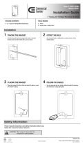
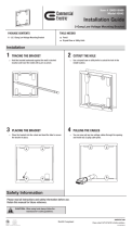
Cutting the Hole
Once you have decided
upon an ideal installation
location for the Wall-
Mounted Volume Control,
hold the Mounting Bracket
up to the wall surface. Level
the Mounting Bracket and
mark the wall by tracing the
inside perimeter of the
Mounting Bracket with a
pencil. Repeat the same
procedure for the In-Ceiling
Speakers using the supplied
template to trace a 9-1/4”
diameter hole for each In-
Ceiling Speaker.
(See Figure 3)
If you are cutting a painted
or wallpapered ceiling, use
a razor-knife to cleanly cut
the wallpaper. Then use a
drywall saw to cut the dry-
wall. (See Figure 4)
Be very careful not to saw
through existing wires,
pipes or structure.
Installing the
Mounting Bracket
Place the Mounting Bracket
against the hole.
(See Figure 5)
Bend the tabs at a 90° angle
and insert into the hole.
(See Figure 6)
When the bracket is secure,
bend the tabs back against
the inside of the drywall and
insert the screws so that they
penetrate the tabs, clamping
the bracket to the drywall.
(See Figure 7)
Running the
Speaker Cable
Conceal the Speaker Cable
between the stereo equip-
ment and the Wall-Mount
Volume Control, and
between the Wall-Mount
Volume Control and the
Speakers.
Be sure to measure the
approximate distance
from your equipment to
the Wall-Mount Volume
Control location, and from
the Wall-Mount Volume
Control to the first and
second Speaker locations
to ensure that you have
enough wire to complete
the installation.
(See Figure 8)
Figure 3
Figure 4
INSTALLATION
!
!
Connecting the
Speaker Cable to
the Volume Control
Connecting the Volume
Control backwards could
damage your amplifier.
Make sure to connect the
Speaker Cable coming
from your amplifier to
the INPUT of the Volume
Control (labeled AMPLIFI-
ER), and the OUTPUT of
the Volume Control
(labeled SPEAKERS) to
the In-Ceiling Speakers.
Strip the wire jacket back 2"
to expose the four colored
conductors and remove 1/4"
of insulation from the end of
each conductor. Twist the
end of each conductor so
the ends are not frayed.
Make sure that no more
than 1/4" of bare wire is
exposed.
Exposing too much wire
could cause the wires to
touch and create a “short”
which could damage
your equipment.
Connect the exposed ends
of each of the Speaker
Cable’s conductors to the
removable connectors pack-
aged with the Wall-Mount
Volume Control. (See
“Connect the wires” at
the bottom of page 7.)
If you are going to connect
more than two pairs of
speakers to the amplifier,
the Volume Control’s
“Impedance Magnifying”
jumpers must be reset.
(See Figure 10, Page 8
of this manual)
Refer to the Installation
section on page 8 of the
VCS-2D-IM Volume Control
manual included with your
Music Anywhere! In-Ceiling
Figure 8
red and black
(unused)
to “speaker”
connection on
volume control
Carefully make a 12" incision in the wire jacket to
expose all four colored conductors (be careful
not to damage the colored conductors inside!).
Cut only the red and black wires at the top of the
incision and strip approx. 3/8" of insulation from
the ends of each conductor. Connect the red and
black wires to the speaker as shown above.
green
Right Speaker
Left Speaker
white
green
red black
red black
see Inset
Inset
Figure 5
white
Figure 7
!
Figure 6

Installing the
Wall-Mount Volume
Control in your Wall
Carefully feed the Speaker
Cable back into the wall
and secure the Wall-Mount
Volume Control to the
bracket using the supplied
screws. Then install the
Decora® faceplate using the
supplied faceplate screws.
(See Figure 9)
Mounting the
In-Ceiling Speakers
Remove the grille from the
In-Ceiling Speaker by bend-
ing the last quarter inch of
a small paper clip into an
“L” shape and inserting it
into one of the holes at the
edge of the grille. Figure 8
illustrates how to connect
the Speaker Cable to the
In-Ceiling Speakers.
Be sure to observe proper
polarity when connecting
the Speaker Cable to the
In-Ceiling Speakers.
Connect the wires:
Red = Right Positive (+)
Black = Right Negative (-)
White = Left Positive (+)
Green = Left Negative (-)
Once the Speaker Cable is
connected to the In-Ceiling
Speaker, conceal the excess
wire inside the ceiling cavity.
To install the in-Ceiling
Speakers, first rotate the
clamps inward so that they
sit flush against the side of
the speaker. Insert the In-
Ceiling Speaker into the
cutout and tighten the
clamps by turning the
screws clockwise with a
drill or by hand.
DO NOT OVERTIGHTEN
THE SCREWS.
Overtightening the screws
may break the clamps or
make the grille difficult
to install.
Carefully install the grille
into the speaker. The grilles
fit tightly to prevent them
from coming loose over
time. Some effort and
care may be required
when installing them.
Figure 9
7
INSTALLATION
!
!
!
8
Connecting the
Speaker Cable to
your Equipment
If your receiver or amplifier
has both “Speakers A” and
“Speakers B” connections
on the rear of the chassis,
connect the Cable connect-
ed to the Speakers to “A”.
Be sure to observe proper
polarity when connecting
the Speaker Cable to your
equipment.
Connect the wires:
Red = Right Positive (+)
Black = Right Negative (-)
White = Left Positive (+)
Green = Left Negative (-)
Connecting
Additional Speakers
and Volume Controls
In order to listen to several
speaker pairs at the same
time, each run of Speaker
Cable (and their respective
Wall-Mount Volume Controls
and Speakers) must be
connected to your amplifier.
This is easily accomplished
by using standard wire nuts
and connecting the other
speaker pairs to your ampli-
fier in the following manner:
a) Simply cut a short
“pigtail” (approximately 12”)
of 4-conductor Speaker
Cable and remove 2” of the
outer sheath from both
ends. Strip 3/8” of the col-
ored insulation from each of
the four conductors at one
end, and connect this end to
your stereo amplifier’s out-
put terminals.
Connect the wires
Red = Right Positive (+)
Black = Right Negative (-)
White = Left Positive (+)
Green = Left Negative (-)
b) Strip 3/4" of insulation
from both the end of the
“pigtail” and from the end
of each of the incoming
Speaker Cable’s conductors.
c) Connect each of the
“pigtail’s” conductors to its
corresponding color on the
incoming Speaker Cable
feeds by twisting the wires
together and securing them
with a wire nut of the
appropriate size.
Protecting Your
Amplifier
The Wall-Mount Volume
Controls included in the
Music Anywhere! Kits
incorporate an “Impedance
Magnifying” feature to
protect your amplifier.
To set the “Magnification
Factor”, simply straddle the
small black “jumper” over
the appropriately marked
“jumper pins” for the correct
magnification setting based
on the number of speaker
pairs in your system.
(see Figure 10)
ADDING ON
SETTING THE MAGNIFICATION FACTOR
1 – 2 speakers pairs set jumper on ..................... 2X
3 – 4 speakers pairs set jumper on ..................... 4X
5 – 8 speakers pairs set jumper on ..................... 8X
9 – 16 speakers pairs set jumper on ................... 16X
16x
MAGNIFICATION
FACTOR
JP1 (LEFT) (RIGHT) JP2
MAGNIFICATION
FACTOR
8x
4x
2x
16x
8x
4x
2x
Left
Jumper
Right
Jumper
Figure 10

SYSTEM OPERATION
9
Every Wall-Mount Volume
Control in the system
must be set to the same
“Impedance Magnification”
factor.
Do not mix other models
of Niles (or any other
manufacturer’s) volume
controls with Niles
VCS-2D-IM Wall-Mount
Volume Controls in this
type of system
configuration.
Normal Operation
Start by presetting the
volume control on your
amplifier at a reasonable
level. The amplifier volume
control is now the Master
Volume for all of your
speakers. Each room Volume
Control enables you to
reduce the volume of that
room without affecting
anyone else.
To control the volume of your
In-Ceiling Speakers, simply
turn the Wall-Mount Volume
Control clockwise to increase
the volume, and counter-
clockwise to decrease the
volume.
When the Volume Control
is all the way down, the
speaker system is complete-
ly off. When the Volume
Control is set all the way up,
the speakers will play at the
amplifier’s preset volume
setting.
Use caution when
listening to your In-Ceiling
Speakers at high volume
levels. Turning up your
amplifier’s volume too far
may cause the amplifier
to run out of power which
can create “clipping”
distortion, which may
potentially damage your
amplifier, volume control,
and speakers.
Typically, an amplifier
reaches its maximum
capabilities when playing
a CD at a 12 o’clock set-
ting. If you increase the
amplifier’s volume control
beyond that point, the
amplifier will begin to
distort. This “clipping”
distortion will quickly
damage the tweeters of
any speaker (regardless
of its power rating —
power ratings refer to
undistorted sound).
If the treble sounds harsh
and unpleasant when you
are standing near your In-
Ceiling Speakers, reduce
the amplifiers volume to a
safe, undistorted level.
!
!
!
!
!
ACCESSORIES
Double-Gang
Mounting Kit
Used for applications
where the mounting of two
Decora
®
style low-voltage
controls next to one another
is desired. This kit includes
a double-gang Decora-style
faceplate, double-gang
mounting bracket, and all
the necessary hardware.
Double-Gang Mounting Kit
Stock# FG00783
10
WDC-100 and
WDC-200
Weatherized Device
Covers
These paintable outdoor
covers are designed to
enable you to install either
single-gang (WDC-100), or
double-gang (WDC-200)
control devices outdoors and
keep them protected from
the elements. Both models
are constructed of durable
Lexan
®
plastic and feature
Neoprene sealing gaskets
and stainless steel mounting
screws.
WDC-100
Stock# FG00289
WDC-200
Stock# FG00290
/