Page is loading ...

Catalog #
Project
Comments
Prepared by
Type
Date
SPECIFICATION FEATURES
10/02/2008 3:34:17 PM
Consult your representative for additional options and finishes.
Specifications and Dimensions subject to change without notice.
ADX040999
ORDERING INFORMATION
ELECTRICAL RATINGS
DESCRIPTION
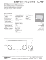
The NCB Series is a premium grade emergency lighting system with all
metal construction that combines functional styling and power performance
capability. These units contain serviceable nickel cadmium batteries and
feature advanced solid-state circuitry.
Electronic
- Dual Voltage Input 120/277
VAC, 60 Hz
- Line-latching
- Solid-state Switching
- Low-Voltage Disconnect
- Brownout Circuit
- Overload/Short Circuit
Protection
- Test Switch/Power
- Indicator Light
Housing Construction
- 18-Gauge Die-Formed
Steel Housing
- 18-Gauge Die-Formed
Steel Cover
Housing Construction Cont.
- Knockout, Conduit or
Cord Set
- Key-hole Mounting Slots
- Corrosion Resistant
White Enamel Finish
Battery
- Serviceable Wet Cell
Nickel Cadmium
- Full Recharge Time:
NCB45, NCB90, NCB110: 24 hrs.
(max.)
- Polarized Battery Terminals
Code Compliance
- UL 924 Listed
- Life Safety NFPA 101
- NEC/OSHA
- Most State and Local Codes
Warranty
- Unit: 1-year
- Battery: 15-year pro-rata
Head/Lamp Data
- Two Heads Standard
- Glare-Free Lens
- Fully Adjustable
- Remote Capability
- High Impact - Thermoplastic
- Matches Housing Finish
NCB
SERIES
6-VOLT
SERVICEABLE WET CELL
NICKEL CADMIUM BATTERY
Emergency Lighting
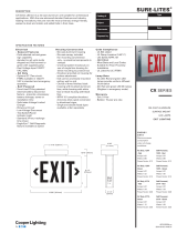
2" [51mm ]
2 1/2 "
[64mm ]
5 3/4"
[146mm]
17 1/4 "
[438mm ]
11 1/2 "
[292mm ]
6" [152mm ] 6" [152mm ]
17"* [432mm ]
8" [203mm ]
6 1/4 "
[159mm ]
ENERGY DAT A
NCB45
Input Current (Max.):
120V= .45A
277V= .17A
NCB90
Input Current (Max.):
120V= .50A
277V= .20A
NCB110
Input Current (Max.):
120V= .81A
277V= .34A
1
Accessories (order separately)
3MSWH=Mounting Shelf (White Finish)
3BRWH=Mounting Brackets (3-White Finish)
WG3=Wire Guard
CSK120=Cord Set (120 VAC)
CSK277=Cord Set (277 VAC)
VS2=Polycarbonate Vandal Shield
VS2WP=Polycarbonate Vandal Shield - Weatherproof
Model Number
NCB45
NCB90
NCB110
SAMPLE NUMBER: NCB110
Options (add as suffix)
MH=Metal Heads
A=Ammeter
TDM=Time Delay Monitor
V=Voltmeter
Alternate Lamps: Consult Cooper
Lighting Representative.
NCB
0, 1, 3 and 4 Heads also available. specify
Cord Set
Mounting Kit
Protective Housing
after cartalog number (i.e. NCB-110408).
*
Order separately.
2
Model DC Voltage 1 1/2 Hours 2 Hours 3 Hours 4 Hours
NCB45
1
6 45 33 22 16
NCB90
1
6 90 67 45 33
NCB110
1
6 110 82 55 41
Rated Wattag e to 87 1/2% of Rated D.C. Voltage Lamp Informat i on
Type Wattage Number
Incandescent
9 29-84
Incandescent 9 29-84
Incandescent 9 29-84
COOPER LIGHTING - SURE-LITES
®

Sure-Lites • Customer First Center • 1121 Highway 74 South • Peachtree City, GA 30269 • TEL 770.486.4800 • FAX 770.486.4801
10/02/2008 3:34:17 PM
Specifications and Dimensions subject to change without notice.
ADX040999
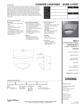
PHOTOMETRICS
TECHNICAL DATA
6-VOLT
NCB SERIES
10
FEET
LEFT
FEET
RIGHT
10
0 10 20 30 40 50 60
FEET FROM LAMP (Measured on axis)
LAMP
AXIS
1FC 0.5 0.3 0.2 0.1
70
0
LAMP
AXIS
10
FEET
LEFT
FEET
RIGHT
10
0 10 20 30 40 50 60
FEET FROM LAMP (Measured on axis)
1FC 0.5 0.3 0.2 0.1
70
0
H o r i z o n t a l D i s t r i b u t i o n
Ve r t i c a l D i s t r i b u t i o n
Lamp No. 29-84 or No. 29-86
Initial Lumens – 29-84 @ 132
29-86 @ 138
Lamp No. 29-84 or No. 29-86
H e a d s
The lamp housing is constructed
of flame-resistant and impact-
resistant injection molded
thermoplastic with matching
finish. The three dimensional
swivel assembly permits
approximate aiming adjustment
from 80° vertical and 358°
rotation. The placement is
secured with a lockable pivot
mounted on a rotating base ring.
L a m p s
Designed specifically for
emergency lighting applications,
the PAR 36 sealed beam type
design insures optimum glare-
free trapezoidal light distribution
along with horizontal and
vertical adjustment by rotating
the lens within the housing.
H o u s i n g
The rugged 18-gauge die-
formed steel housing is finished
with white corrosion-resistant
polyester powder coat paint.
Cabinet has keyhole mounting
slots and knockouts in top, rear
and side for AC/DC wiring
connections. Front cover has
large viewport to allow visual
inspection of electrolyte level
and removable cover provides
easy access to filler caps on
the battery(s).
L i n e - L a t c h e d
Sure-Lites’ line-latched
electronic circuitry makes
installation easy and
economical. A labor efficient
AC-activated load switch
prevents the lamps from
turning on during installation
to a non-energized AC circuit.
Line-latching eliminates the
need for a contractor’s return
to a job site to connect the
batteries when the building’s
main power is permanently
turned on.
S o l i d - S t a t e C h a r g e r
Supplied with a 120/277 VAC,
voltage regulated solid-state
charger. Immediately upon
restoration of AC current after
a power failure, the charger
provides a high charge rate.
The charge circuit reacts to
the condition of the battery
and alters the rate of charge in
order to maintain peak battery
capacity and maximize battery
life. Solid-state construction
recharges the battery following
a power failure in accordance
with UL 924.
O v e r l o a d a n d S h o r t
C i r c u i t P r o t e c t i o n
The solid-state overload
monitoring device in the DC
circuit disconnects the lamp
load from the battery should
excessive wattage demands
be made and automatically
resets when the overload or
short circuit is removed. This
overload current protective
feature eliminates the need
for fuses or circuit breakers
for the DC load.
B r o w n o u t C i r c u i t
The brownout circuit in Sure-
Lites’ units monitors the flow
of AC current to the unit and
activates the emergency
lighting system when a
predetermined reduction
of AC power occurs. This
dip in voltage will cause most
ballasted fixtures to extinguish
causing loss of normal lighting
even though a total power
failure has not occurred.
S o l i d - S t a t e Tra n s fer
The unit incorporates a solid-
state switching transistor which
eliminates corroded and pitted
contacts or mechanical failures
associated with relays. The
switching circuit is designed to
detect a loss of AC voltage and
automatically energizes the
lamps. Upon restoration of
the AC power, the emergency
lamps will switch off and the
charger will automatically
recharge the battery.
L o w -Vol t a g e D i s c on n e c t
When the battery’s terminal
voltage falls below 80% of the
rated voltage, the low-voltage
circuitry disconnects the
lighting load. The disconnect
remains in effect until normal
utility power is restored,
preventing deep battery
discharge.
Te s t S w i t c h/ P o w e r I n d i ca t o r
L i g
ht
Conveniently located Test
Switch allows for manual
verification of proper
operation of the transfer
circuit and emergency lamps.
The Power Indicator Light
provides visual assurance that
the AC power is on.
S er v i c e a b l e N i c k e l
C a d
m i u m B a t t e r y
The wet cell pocket plate nickel
cadmium battery remains the
premier battery for emergency
lighting applications. Designed
with an extra large electrolyte
reservoir, these batteries
require maintenance every
three to five years under
normal ambient conditions.
More frequent maintenance is
required when operated at an
elevated temperature. The
sintered plate design should
provide up to twenty-five
years of service if properly
maintained.
W a rr a n t y
All Sure-Lites’ units are backed
by a firm one-year warranty
against defect in material and
workmanship (excluding
lamps). Serviceable, long-life,
nickel cadmium batteries carry
a fifteen-year pro-rata warranty.
/