(English)
DM-RBSL001-03
Dealer's Manual
ROAD MTB Trekking
City Touring/
Comfort Bike
URBAN SPORT E-BIKE
Shifting lever
SORA
ST-R3000
ST-R3030
SL-R3000
SL-R3030
CLARIS
ST-R2000
ST-R2030
SL-R2000
SL-R2030
Non-Series
ST-RS200
ST-RS203

2
CONTENTS
IMPORTANT NOTICE .............................................................................................. 4
TO ENSURE SAFETY ............................................................................................... 5
Shifting lever (Dual control lever) 7
LIST OF TOOLS TO BE USED .................................................................................. 9
INSTALLATION ..................................................................................................... 11
Installation to the handlebar ....................................................................................................................11
Installation of the brake cable ..................................................................................................................12
Installation of the shifting cable ...............................................................................................................13
ADJUSTMENT ...................................................................................................... 18
Lever stroke adjustment ............................................................................................................................18
MAINTENANCE .................................................................................................... 20
Disassembling the bracket body and lever body .....................................................................................20
Assembling the bracket body and lever body .......................................................................................... 21
Replacing the bracket cover ......................................................................................................................22
Replacing the name plate .........................................................................................................................22
Replacing the main lever support .............................................................................................................23
Replacing the SL cable guide .....................................................................................................................25
Replacing the cable cover .......................................................................................................................... 26
How to pull out a disconnected inner end (shifting cable) .....................................................................27

3
Shifting lever (RAPIDFIRE Plus) 28
LIST OF TOOLS TO BE USED ................................................................................ 30
INSTALLATION ..................................................................................................... 32
Installation to the handlebar ....................................................................................................................32
MAINTENANCE .................................................................................................... 34
Replacing the inner cable ..........................................................................................................................34
Replacement and reassembly of the indicator unit .................................................................................35
Replacing the cover ....................................................................................................................................38
Shifting lever 39
LIST OF TOOLS TO BE USED ................................................................................ 41
INSTALLATION ..................................................................................................... 43
Installation to the handlebar ....................................................................................................................43
Installation of the brake cable ..................................................................................................................43
ADJUSTMENT ...................................................................................................... 45
Lever stroke adjustment ............................................................................................................................45
MAINTENANCE .................................................................................................... 47
Replacing the inner cable ..........................................................................................................................47

4
IMPORTANT NOTICE
IMPORTANT NOTICE
•
This dealer's manual is intended primarily for use by professional bicycle mechanics.
Users who are not professionally trained for bicycle assembly should not attempt to install the components themselves using the dealer's manuals.
If any part of the information on the manual is unclear to you, do not proceed with the installation. Instead, contact your place of purchase or a local
bicycle dealer for their assistance.
•
Make sure to read all instruction manuals included with the product.
•
Do not disassemble or modify the product other than as stated in the information contained in this dealer's manual.
•
All dealer's manuals and instruction manuals can be viewed on-line on our website (http://si.shimano.com).
•
Please observe the appropriate rules and regulations of the country, state or region in which you conduct your business as a dealer.
For safety, be sure to read this dealer's manual thoroughly before use, and follow it for correct use.
The following instructions must be observed at all times in order to prevent personal injury and physical damage to equipment and surroundings.
The instructions are classified according to the degree of danger or damage which may occur if the product is used incorrectly.
DANGER
Failure to follow the instructions will result in death or serious injury.
WARNING
Failure to follow the instructions could result in death or serious injury.
CAUTION
Failure to follow the instructions could cause personal injury or physical damage to equipment and surroundings.

5
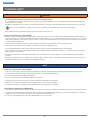
TO ENSURE SAFETY
TO ENSURE SAFETY
WARNING
•
Be sure to follow the instructions provided in the manuals when installing the product.
It is recommended to use genuine Shimano parts only. If parts such as bolts and nuts become loose or damaged, the bicycle may suddenly fall over,
which may cause serious injury.
In addition, if adjustments are not carried out correctly, problems may occur, and the bicycle may suddenly fall over, which may cause serious injury.
•
Be sure to wear safety glasses or goggles to protect your eyes while performing maintenance tasks such as replacing parts.
•
After reading the dealer's manual thoroughly, keep it in a safe place for later reference.
Be sure to also inform users of the following:
•
Each bicycle may handle slightly differently depending on the model. Therefore, be sure to learn the proper braking technique (including brake lever
pressure and bicycle control characteristics) and operation of your bicycle. Improper use of your bicycle's brake system may result in a loss of control or
a fall, which could lead to severe injury. For proper operation, consult a professional bicycle dealer or the bicycle's owner's manual. It is also important
to practice riding and braking, etc.
•
If the front brake is applied too strongly, the wheel may lock and the bicycle may fall forward, and serious injury may result.
•
Always make sure that the front and rear brakes are working correctly before riding the bicycle.
•
The required braking distance will be longer during wet weather. Reduce your speed and apply the brakes early and gently.
•
If the road surface is wet, the tires will skid more easily. If the tires skid, you may fall off the bicycle; therefore, to avoid this, reduce your speed and
apply the brakes early and gently.
•
Because of the characteristics of the carbon fiber material, the lever should never be altered. Otherwise, the lever may break preventing braking
operation.
•
Check before riding that there is no damage such as carbon peeling or cracking. If there is any damage, stop using the bicycle and consult a dealer or
an agency. Otherwise, the lever may break preventing braking operation.
NOTE
Be sure to also inform users of the following:
•
In the case of carbon levers, wash them with a soft cloth using a neutral detergent. Otherwise, the material may break down and be damaged.
•
Avoid leaving the carbon levers in areas of high temperature. Also keep them well away from fire.
•
Be sure to keep turning the crank during gear shifting.
•
Be sure to keep turning the crank during the shifting lever operation.
•
If gear shifting operations do not feel smooth, wash the derailleur and lubricate all moving parts.
•
Products are not guaranteed against natural wear and deterioration from normal use and aging.
•
For maximum performance we highly recommend Shimano lubricants and maintenance products.
For Installation to the Bicycle, and Maintenance:
•
Using a frame with internal cable routing is strongly discouraged as it has tendencies to impair the SIS shifting function due to its high cable resistance.
•
Use an outer casing which still has some length to spare even when the handlebars are turned all the way to both sides. Furthermore, check that the
shifting lever does not touch the bicycle frame when the handlebars are turned all the way.
•
Use an outer casing [OT-SP41] and a cable guide (SM-SP17/SP18) for smooth operation.

6
TO ENSURE SAFETY
•
Grease the inner cable and the inside of the outer casing before use to ensure that they slide properly. If the grease on the inner cable is wiped off,
the application of SIS SP41 grease (Y04180000) is recommended. Do not let soil and dirt adhere to the inner cable.
•
A special grease is used for the gear shifting cable. Do not use premium grease or other types of grease, otherwise they may cause deterioration in
gear shifting performance.
•
If gear shifting adjustments cannot be carried out, check that the rear fork ends are aligned. Check whether the cable is lubricated and clean, and if
the outer casing is too long or short.
The actual product may differ from the illustration because this manual is intended mainly to explain the procedures for using
the product.

Shifting lever
(Dual control lever)

LIST OF TOOLS TO BE USED

9
LIST OF TOOLS TO BE USED
LIST OF TOOLS TO BE USED
The following tools are needed for installation, adjustment, and maintenance purposes.
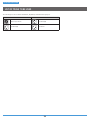
Tool Tool Tool
2mm hexagon wrench Screwdriver[#1] TL-CT12 cable cutter
5mm hexagon wrench Plastic mallet
Shimano original E-ring removal tool
(Y6RT66000/Y6RT68000)

INSTALLATION

11
INSTALLATION
Installation to the handlebar
INSTALLATION
Installation to the handlebar
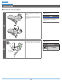
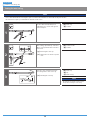
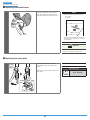
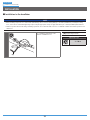
1
(A)
Turn over the bracket cover from the
back side.
Gently turn over the ends of the bracket
cover with both hands and slowly push
them down.
(A)
Clamp bolt
NOTE
Forcibly pulling it may cause damage to the
bracket cover because of its material
properties.
2
(A)
Use a 5mm hexagon wrench to tighten
the clamp bolt at the top of the bracket.
(A)
Clamp bolt
Tightening torque
6 - 8 N·m

12
INSTALLATION
Installation of the brake cable
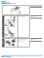
Installation of the brake cable
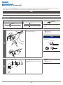
Be careful not let the BC-9000/BC-R680 inner cable come into contact with the shifting lever or the metal section (adjustment section) of the caliper
brake. When the inner cable is installed, coating may be damaged and become fluffy; however, it will not affect function.
NOTE
Use a cable which still has some length to spare even when the handlebars are turned all the way to both sides.
Cable used
Inner cable Outer casing
Ø1.6mm
Ø5mm
TECH TIPS
For information on how to install the brake
cable, refer to the dealer's manual for the
brake.
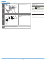
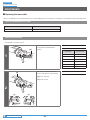
1
(C)
(B)(A)
Depress the lever as if to brake and pass
the brake cable through.
(A)
Inner end
(B)
Cable hook
(C)
Outer casing
NOTE
Make sure that the inner end is firmly set in
the cable hook.
Cable hook
Inner end
2
(B)
(A)
(A)
(A) (A)
Temporarily secure the outer casing to
the handlebar (by using tape or a similar
material).
(A)
Tape
(B)
Outer casing

13
INSTALLATION
Installation of the shifting cable
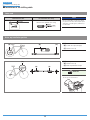
Installation of the shifting cable
Cable used
Dedicated inner cable Recommended outer casing
Opposite side
Ø1.2mm
Normal outer cap/SP41 outer casing
SP41
Ø4mm
NOTE
Do not let dust adhere on the inner cable. If
the grease on the inner cable is wiped off, the
application of SIS SP41 grease (Y04180000) is
recommended.
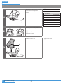
Outer cap installation position
(B) (C)(A)
(A)
Derailleur side
(B)
Sealed outer cap (resin type)
(C)
Normal outer cap
(B)
(A)
(C)
(A)
Shifting lever side
(B)
Normal outer cap
(C)
Outer cap with short tongue
TECH TIPS
Be sure to insert the convex shape on the cap
into the groove in the bracket.

14
INSTALLATION
Installation of the shifting cable
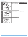
Cutting the outer casing
NOTE
•
Use a cable which still has some length to spare even when the handlebars are turned all the way to both sides.
•
Be careful not to injure your hand with the TL-CT12 needle section.
1
SP41
(A)
(B)
Use the cable cutter (TL-CT12) or an
equivalent tool to cut the side opposite
of the inscription.
(A)
Outer cap
(B)
TL-CT12
2
SP41
(A)
(B)
(y)
(z)
After cutting, expand the tip of the liner
(Ø 2.2 or more) with TL-CT12 or another
narrow tool.
(y)
Removing the outer cap
(z)
Arrange the cut end into a perfect
circle
(A)
TL-CT12 needle
(B)
TL-CT12
3
(z)
SP41
(A)
(C)
(B)
Insert the outer casing until it touches
the seating surface of the outer cap.
(z)
Installing the outer cap
(A)
Outer cap
(B)
Tip
(C)
Outer casing
NOTE
Be careful not to crush the convex section of
the tip when inserting the outer casing.

15
INSTALLATION
Installation of the shifting cable
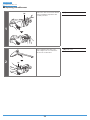
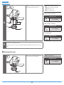
Passing through the shifting inner cable
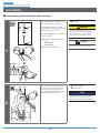
1
(A)
Operate lever [B] and set it to the top
position, then attach the cable and make
adjustments.
(A)
Lever [B]
TECH TIPS
The illustration is of the rear lever.
2
(B)
(A)
Remove the cable cover using a slotted
screwdriver or similar flat-tipped tool.
(A)
Cable cover
(B)
Slotted screwdriver
3
Put the inner cable through as shown in
illustration.
NOTE
Insert the cable while being careful not to
damage the coating.
4
Insert the cable in such a manner that
the inner end is attached to the unit.
5
(A)
Put the inner cable through as shown in
illustration.
(A)
Outer cap with short tongue
To be continued on next page

16
INSTALLATION
Installation of the shifting cable
6
(A)
Finally, reinstall the cable cover.
(A)
Cable cover
TECH TIPS
When the inner cable is installed, coating may
be damaged and become fluffy; however, it
will not affect function.
7
(B)
(A)
(A)
(A) (A)
Temporarily secure the outer casing to
the handlebar (by using tape or a similar
material).
(A)
Tape
(B)
Outer casing
8
Then wrap the handlebar with handlebar tape.

ADJUSTMENT

18
ADJUSTMENT
Lever stroke adjustment
ADJUSTMENT
Lever stroke adjustment
(A)
(B)
(z)
(x)(y)
Adjust the lever stroke using a 2mm
hexagon wrench.
(x)
Clockwise: The lever stroke
becomes smaller.
(y)
Counterclockwise: The lever
stroke becomes larger.
(z)
Lever stroke
(A)
2mm hexagon wrench
(B)
Reach adjustment bolt
NOTE
Make sure that braking operates properly
after the adjustment.

MAINTENANCE

20
MAINTENANCE
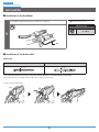
Disassembling the bracket body and lever body
MAINTENANCE
Disassembling the bracket body and lever body
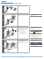
1
[1] [2]
[A]
[B]
(A)
(z)
(y)
First use the Shimano original tool (sold
separately) to remove the E-ring.
Use part [B] of the Shimano original
E-ring removal tool [2] to align the E-ring
with the direction of removal.
Next, set part [A] against the E-ring and
remove the E-ring.
(y)
Shimano original E-ring removal
tool:
[1] Y6RT66000
[2] Y6RT68000
(z)
E-ring removal direction
(A)
E-ring
CAUTION
When you remove the E-ring, it may pop out;
wear protective glasses while removing it.
Check that there is no one and nothing
around you before starting the removal.
TECH TIPS
The illustration is of the right-hand lever.
2
(A)(B)
Insert a hexagon wrench or similar tool
into the lever axle hole, tap it gently
with a plastic mallet to push out the
lever axle, which disassembles it into the
bracket body and the lever body.
(A)
Hexagon wrench
(B)
Plastic mallet
NOTE
Always be sure to remove the lever axle in this
direction. If it is removed in the opposite
direction, it may damage the bracket body.
Page is loading ...
Page is loading ...
Page is loading ...
Page is loading ...
Page is loading ...
Page is loading ...
Page is loading ...
Page is loading ...
Page is loading ...
Page is loading ...
Page is loading ...
Page is loading ...
Page is loading ...
Page is loading ...
Page is loading ...
Page is loading ...
Page is loading ...
Page is loading ...
Page is loading ...
Page is loading ...
Page is loading ...
Page is loading ...
Page is loading ...
Page is loading ...
Page is loading ...
Page is loading ...
Page is loading ...
Page is loading ...
-
 1
1
-
 2
2
-
 3
3
-
 4
4
-
 5
5
-
 6
6
-
 7
7
-
 8
8
-
 9
9
-
 10
10
-
 11
11
-
 12
12
-
 13
13
-
 14
14
-
 15
15
-
 16
16
-
 17
17
-
 18
18
-
 19
19
-
 20
20
-
 21
21
-
 22
22
-
 23
23
-
 24
24
-
 25
25
-
 26
26
-
 27
27
-
 28
28
-
 29
29
-
 30
30
-
 31
31
-
 32
32
-
 33
33
-
 34
34
-
 35
35
-
 36
36
-
 37
37
-
 38
38
-
 39
39
-
 40
40
-
 41
41
-
 42
42
-
 43
43
-
 44
44
-
 45
45
-
 46
46
-
 47
47
-
 48
48


Ask a question and I''ll find the answer in the document
Finding information in a document is now easier with AI
Related papers
-
Shimano BB-UN70 Exploded View
-
Shimano SL-M3100 Dealer's Manual
-
Shimano SL-U5000 Dealer's Manual
-
Shimano ST-RX810-LA Dealer's Manual
-
Shimano SM-RT800 Dealer's Manual
-
Shimano BR-RS505 Dealer's Manual
-
Shimano SM-RT500-SS Dealer's Manual
-
Shimano BR-RS405 Dealer's Manual
-
-
Shimano BL-M820 Exploded View