Page is loading ...

Pg. 1/6 MAN#650139
DCC-2200 / DCC-2300
CLIMATE CONTROL MODULE
for Vintage Air Gen II Modules
TO AVOID DAMAGE TO GEN II UNIT, READ IMPORTANT NOTE IN INSTALLATION
INSTRUCTIONS BEFORE BEGINNING INSTALLATION!!!
WHITE
BLACK
DO NOT USE
BLUE
GREEN
+12V WITH KEY ON
CABIN TEMP
SENSOR
COMPRESSOR
SAFETY
SWITCH
COMPRESSOR
CLUTCH
+12 BATTERY
FUSED 30A
DCC-2200
AUTOMATIC CLIMATE CONTROL
EVAPORATOR PROBE
PINK
BLUE
GREEN
YELLOW
GEN II
MODULE
TO
DISPLAY
FAN
MOTOR
FAN
CONTROL
MODULE
PINK
ORANGE
GREEN
YELLOW
+12V WITH KEY ON
RED
BLACK
shield wire
back of display
mounting
stud
to controller
DIM
IGN
CABIN-
CABIN+
VENT-
VENT+
FLOOR-
FLOOR+
GND
FAN MED
A/C
FAN HI
+12V
EVP-(R)
EVP+(Y)
VENT TEMP
SENSOR
FLOOR TEMP
SENSOR
RED
YELLOW
RED
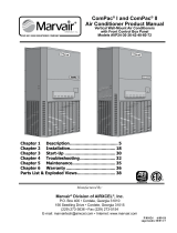
Figure 1: Wiring diagram

Pg. 2/6 MAN#650139
CLIMATE CONTROL DISPLAY
10. Temperature scale
1. Fan speed
indicator
4. A/C mode indicator
7. Duct mode indicator
9. Temperature up
2. Fan speed up
5. A/C mode select
6. Duct mode select
11. Set temperature
3. Fan speed down
8. Temperature down
F
^
^
72
^
^
FAN
A/C FLOOR
1. Fan speed indicator
This portion of the display indicates the currently selected fan speed. When the climate control unit is off it will
read as “FAN OFF”. In manual speed selection mode there are 7 speeds depicted by an increasing number of
large blocks. When all 7 large blocks are showing, the fan is at the highest speed. The next upper fan button
press will then place the fan into auto mode, depicted “FAN AUTO”. Here the fan speed is automatically set as
needed.
2. Fan speed up
Pressing the fan speed up button will increase the speed of the fan. If the unit is off, pressing this button turns the
unit on. If pressed when the fan is at the fastest setting, the fan will be put in auto mode.
3. Fan speed down
Pressing this button will remove the fan from auto operation and decrease fan speed with each press. When fan
is at lowest setting, pressing fan speed down button will turn the unit off.
4. A/C mode indicator
This indicator displays if the air conditioner is turned on or off. If the air conditioner is on, “A/C” is displayed.
“ECON” is displayed when it is off.
5. A/C mode select
Pressing this button toggles the air conditioning between on and off. Hold this button while turning the key on to
get to the setup menu.
6. Duct mode select
Pressing this button moves through the different modes of the Gen II module ductwork. The order of modes is
FLOOR air is blown out the floor vents of ductwork
BiLev air is blown out of the vents and onto the floor
DEF air is blown onto windshield (May be disabled if duct has no defrost. See setup)
VENT all air is blown out the vents
7. Duct mode indicator
This indicator displays the current duct mode. These modes are listed and described above.
8. Temperature down
Pressing this button decreases the set cabin temperature. The minimum controlled temperature is 60ºF or 15ºC.
Pressing the temperature down button again at the minimum controlled temperature changes the temperature to
55ºF or 13ºC. At this setting, the temperature is no longer controlled and the air conditioning is at maximum. This
is useful for quickly cooling a hot cabin.
9. Temperature up
Pressing this button increases the set cabin temperature. The maximum controlled temperature is 85ºF or 29ºC.
Pressing the temperature up button again at the maximum controlled temperature changes the temperature to
90ºF or 32ºC. At this setting, the temperature is no longer controlled and the heat is on maximum. This is useful
for rapidly heating the cabin.
10. Temperature scale
This signifies the current temperature scale in use. To change the temperature scale, see setup instructions.
11. Set temperature
This displays the current set cabin temperature. This is the goal temperature the unit attempts to maintain.

Pg. 3/6 MAN#650139
SETUP
The setup menu allows customization of the climate control system and viewing of system information. Use the following
steps for making changes to the setup.
1. Start with the key OFF.
2. Press and hold MODE button then turn the key to on.
3. The setup screen will appear with “EXIT SETUP” highlighted at the top.
4. Use the FAN up and down button to select the desired setup option (Selected option is highlighted).
5. Press the TEMP up or down button to change settings for selected option
6. To leave setup turn the key off or select “EXIT SETUP” and press TEMP up or down
The available options in the setup menu in order from top to bottom are:
EXIT SETUP
This option allows exit from the setup menu by pressing either the TEMP up or down buttons when EXIT SETUP
is highlighted. Setup may also be exited at any point by turning the ignition off.
TEMP SCALE
This option selects how the temperature is displayed. Selecting F displays temperatures in Fahrenheit. Selecting
C displays temperatures in Celsius.
AUTO HIGH
This option regulates the use of high speed when the fan is in auto mode. When set to ON, the fan is allowed to
go into high speed when needed. If set to OFF, the fan will not go into high mode with fan in auto. High fan
speeds may still be achieved by manually setting the fan speed to high. This option is provided to allow the cabin
noise from the high fan to be reduced. It is important to note that, depending on the vehicle, the system may have
difficulty maintaining the desired temperature without the fan high speed.
DEF
This option allows defrost to be turned off for Gen II modules that do not have defrost capability. Use the
ENABLED setting for systems equipped with defrost. Use the DISABLED setting if defrost is not available.
MIN AC TMP
This option allows the minimum evaporator temperature to be set. If the GEN module freezes up, setting this to a
higher temperature should fix the problem. This setting is always displayed in degrees Fahrenheit.
CAB SIZE
This option sets the size of the vehicle. The three options are SML (small), MED (medium), LRG (large). This
setting effects how tightly the temperature is controlled. The small setting keeps the temperature within a much
smaller range around the set point but may toggle between heating and cooling and use more of the high fan
setting in a larger cabin. The large cabin setting allows for a little more difference from the set temperature but will
do less “hunting” for the set temperature in the large cabins. Set this according to preference for your vehicle.
VER
This menu option allows viewing of software code versions for the climate control system. The technician may
need these version numbers to troubleshoot problems with the system.
INSTALLATION
The DCC-2200/2300 is designed to work with the GEN II module from Vintage Air. See the Vintage Air manual for the
installation instructions for the GEN II module. If the GEN II module is not yet installed, it may be easier to put the
temperature sensors into the module before installing it into the vehicle.
IMPORTANT NOTE!!!
When drilling into the GEN module to install
sensors, care must be taken not to drill too deep!
Drilling too deep may puncture the coils in the
evaporator permanently damaging the GEN module!
To prevent drilling too deep, place a piece of 3/8”
I.D. rubber hose over the drill bit leaving only about
¼ inch of drill bit exposed (see Figure 2 at right).
Figure 2: Example of drill stop using a piece of
rubber hose to prevent drilling too deep.

Pg. 4/6 MAN#650139
STEP 1 VENT SENSOR INSTALLATION:
Using a 3/8” drill bit, with a hose
installed (see important note above),
drill a hole in the case in the side
containing the vent and floor outlets
(see figure 3) at location A (figures
5,6). This hole should be placed at
about the center of the module, about
¾” above the seam of the case (with
vent openings as top). Push one of
the temp sensors into this hole,
leaving the wires to the outside. This
sensor will be wired to the VENT+ and
VENT- terminals on the control box as
shown in the wiring diagram on the
first page (figure 1).
STEP 2 FLOOR SENSOR INSTALLATION:
Using a 3/8” drill bit, with hose
installed (see important note), drill a
hole in the GEN II case in the floor
outlet ducting at point B (figures 5,6).
Insert the second temperature sensor
into the hole so that the wires are to
the outside of the duct. This sensor
will be wired to the FLOOR+ and
FLOOR- terminals on the control box
as shown in wiring diagram.
STEP 3 CABIN SENSOR INSTALLATION:
Using a 3/8” drill bit, with hose
installed (see important note) drill a
hole in the fan shroud at point C
(figures 5,7). Insert the last sensor into
the hole with the wires to the outside.
This sensor will be wired to the
CABIN- and CABIN+ terminal on the
control box as shown in the wiring
diagram.
STEP 4 EVAPORATOR PROBE INSTALL:
Push the evaporator probe into the
hole in the GEN II module marked
with the sticker for the capillary tube.
The metal portion of the probe should
go almost completely into the GEN II
unit.
Figure 5: COMPAC or SUPER temp sensor placement. A) vent sensor
B) floor sensor C) cabin sensor
Figure 3: Drilling the hole for the vent sensor in a GEN II Compac unit. Note
the hose on the drill bit to prevent drilling too deep.
Figure 4: GEN II Compac unit with input, vent, and
floor sensors installed.
Figure 6: MINI temp sensor placement. A) vent sensor B) floor sensor
Figure 7: MINI Cabin temp sensor placement. (point C)

Pg. 5/6 MAN#650139
STEP 5 GEN II INSTALLATION: If the GEN II module is not yet installed in the vehicle, do so now. Refer to the
GEN II manual for installation instructions.
STEP 6 MODE WIRE CONNECTION: Connect the four color coded wires to the control wires from the GEN II
module. These are the wires that would typically go to the mode switch on the GEN II control panel. If the
GEN II module is not equipped with defrost, leave the green wire unconnected. Plug the connector for the
heat control into the 3 pin connector labeled “HEAT” on the DCC-2200 controller.
STEP 7 TEMP SENSOR WIRING: Connect the temp sensors to the controller as shown in the wiring diagram.
The vent, floor and cabin sensors have two wires. The black wire is connected to the – terminal and the
other wire is connected to the + terminal of each sensor inputs. Connect the RED wire of the evaporator
probe to the EVP-(R) terminal and the YELLOW wire to the EVP+(Y) terminal. The evaporator probe must
be connected directly to the control box. DO NOT EXTEND THE WIRES OF THE EVAPORATOR
PROBE! This will cause it to read temperature incorrectly.
STEP 8 REMAINING CONNECTIONS: Connect remaining connections from terminal strip as shown in wiring
diagram (see figure 1). NOTE: The ground connection from the fan control module should share a ground
location with the fan. A/C clutch output should drive a relay which supplies power to the A/C clutch
THROUGH the A/C safety switch.
STEP 9 MOUNTING DISPLAY PANEL: Using the provided template, or a template provided by Vintage Air, make
the dash cutout for the display. Insert the display from front and clamp into dash from rear with provided
clamps. Secure by tightening nuts onto clamp.
STEP 10 CONNECT DISPLAY: Connect display to control unit with supplied wiring harness. Fasten the shield wire
eyelet from the display end of harness to the display case using one of the display mounting studs.
Secure the eyelet with clamp nut (see figure 1).
TROUBLESHOOTING
PROBLEM
CAUSE
SOLUTION
Display reads
“Communication error”
Poor display harness connection
No battery connection
Check plug at display and controller for proper connection
and check for break or pinch in wire.
Ensure that there is 12V on the red wire of the fan control
module. Also ensure that the pink wire of the fan control
module is connected to the PWR terminal of the controller.
Display reads “Shorted
cabin / vent / floor temp
sensor”
Sensor is shorted
Sensor not connected properly
Bad ground on sensor
Check for pinched sensor wires
Check that sensor is connected as shown in wiring diagram.
Make sure all sensors ground to the ground terminal on
controller NOT a chassis ground.
Display reads “open cabin /
vent / floor temp sensor”
Sensor wire broken / shorted
Sensor disconnected or not connected
properly
Bad ground on sensor
Examine for pinched or broken wires to the sensor
Check that sensor is connected as shown in wiring diagram.
Make sure all sensors ground to the ground terminal on
controller NOT a chassis ground.
Display does not light up at
key on
Bad connection on IGN terminal
Poor harness connection to display
Make sure that there is 12V at IGN terminal with key on.
Check plug at display and controller for proper connection
and check wires for pinches or breaks.
Fan will only run on high.
Broken medium fan wire connection
Check that medium fan wire is connected to FAN MED
terminal on controller and check wire for pinches or breaks.
Fan will not run in high
Auto high set to off in setup
Poor connection to fan high circuit
Enter setup and set Auto high to on.
Check connection from controller to fan module for breaks or
pinched wire.
Fan does not run
Fan is set to off.
No ignition signal at fan module
Poor ground on fan motor
Press the fan up button to turn fan on.
Check for 12v on yellow wire of fan module with key on.
Check ground wire on fan motor for good ground.

Pg. 6/6 MAN#650139
System does not cool
A/C mode in ECON
Evaporator froze up (indicated by low
air movement from ducts)
Poor connection to A/C relay and clutch
Evaporator probe sensor not properly
connected, installed.
Poor connection on heat adjust plug.
Temperature sensors not connected
properly
Press A/C button until display reads “A/C”
Place in ECON mode and raise temp setting to allow
evaporator to thaw. Raising MIN AC TMP setting in setup
should prevent future freezing of evaporator.
Check for broken or pinched wire to A/C relay, safety switch
and clutch.
Check for broken or pinched wires to evaporator probe.
Check probe for proper insertion into Gen II module.
Check for proper connection of heat adjust plug. Check for
broken or pinched wires on plug.
Ensure temperature sensors are connected as described in
wiring diagram.
System does not heat
Poor connection on heat adjust plug.
Temperature sensors not connected
properly
Check for proper connection of heat adjust plug. Check for
broken or pinched wires on plug.
Ensure temperature sensors are connected as described in
wiring diagram.
System does not blow out
of vents / defrost / floor as
expected
Poor connection on mode wires (color
coded wires to Gen II module)
Defrost set to on for non-defrost system
Evaporator core froze up
Check for good connection of blade terminals on wires.
Check for pinched or broken wires.
Enter setup and set DEF option to DISABLED
Place in ECON mode and raise temp setting to allow
evaporator to thaw. Raising MIN AC TMP setting in setup
should prevent future freezing of evaporator.
Cannot set system to
defrost
Defrost set to disabled on system with
defrost
Enter setup and set DEF to ENABLED
SERVICE AND REPAIR
DAKOTA DIGITAL offers complete service and repair of its product line. In addition, technical consultation is available to help you work through any questions or
problems you may be having installing one of our products. Please read through the Troubleshooting Guide. There, you will find the solution to most problems.
Should you ever need to send the unit back for repairs, please call our technical support line, (605) 332-6513, to request a Return Merchandise Authorization
number. Package the product in a good quality box along with plenty of packing material. Ship the product by UPS or insured Parcel Post. Be sure to include the RMA
number on the package, and include a complete description of the problem with RMA number, your full name and address (street address preferred), and a telephone number
where you can be reached during the day. Any returns for warranty work must include a copy of the dated sales receipt from your place of purchase. Send no money. We will
bill you after repair.
Dakota Digital 24 Month Warranty
DAKOTA DIGITAL warrants to the ORIGINAL PURCHASER of this product that should it, under normal use and condition, be proven defective in material or
workmanship within 24 MONTHS FROM THE DATE OF PURCHASE, such defect(s) will be repaired or replaced at Dakota Digital’s option.
This warranty does not cover nor extend to damage to the vehicle’s systems, and does not cover removal or reinstallation of the product. This Warranty does not
apply to any product or part thereof which in the opinion of the Company has been damaged through alteration, improper installation, mishandling, misuse, neglect, or
accident.
This Warranty is in lieu of all other expressed warranties or liabilities. Any implied warranties, including any implied warranty of merchantability, shall be limited to
the duration of this written warranty. Any action for breach of any warranty hereunder, including any implied warranty of merchantability, must be brought within a period of 24
months from date of original purchase. No person or representative is authorized to assume, for Dakota Digital, any liability other than expressed herein in connection with
the sale of this product.
WARNING: This product can expose you to chemicals including lead, which is known to the State of California to
cause cancer and birth defects or other reproductive harm. For more information go to www.P65Warnings.ca.gov
/