
Call-UPS II
AP9208
AP9608

Thank You !
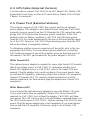
Thank you for selecting this American Power Conversion Call-UPS II remote
control accessory. Whether you have the SmartSlot or external version, your
Call-UPS II has been designed for many years of reliable, maintenance-free
service in combination with your American Power Conversion Uninterruptible
Power Supply. American Power Conversion is dedicated to the development of
high-performance electrical power conversion and control products and we
hope that you will find this product a valuable, convenient addition to your
computing system.
Please read this manual! It provides installation and operating instructions
that will help you get the most from your Call-UPS II accessory.
Save this manual! It includes important instructions for the safe installation
of your Call-UPS II accessory. Further, it includes instructions for obtaining
factory service should the proper operation of the accessory come into
question.
Radio frequency interference
WARNING: Changes or modifications to this unit not expressly approved by
the party responsible for compliance could void the users authority to operate
the equipment.
NOTE: This equipment has been tested and found to comply with the limits for
a Class A digital device pursuant to Part 15 of the FCC Rules. These limits are
designed to provide reasonable protection against harmful interference when
the equipment is operated in a commercial environment. This equipment
generates, uses, and can radiate radio frequency energy and, if not installed and
used in accordance with the instruction manual, may cause harmful interference
to radio communications. Operation of this equipment in a residential area is
likely to cause harmful interference in which case the user will be required to
correct the interference at his own expense.
Shielded communications cables must be used with this unit
to ensure compliance with the Class A FCC limits.
This digital apparatus does not exceed the Class A limits for radio noise
emissions from digital apparatus set out in the Radio Interference Regulations of
the Canadian Department of Communications.
Le présent appareil numérique német pas de bruits radioélectriques dépassant
les limites applicables aux appareils numériques de la Class A prescrites dans le
Règlement sur le brouillage radioélectrique édicté par le ministère des Commu-
nications du Canada.

i
Contents
1 Introduction . . . . . . . . . . . . . . . . . . . . . . . . 1
1.1 Overview 1
1.2 Hardware Requirements 1
2 Product Description . . . . . . . . . . . . . . . . . . . 2
2.1 The Call-UPS II Panel 2
2.2 Management Port 2
2.3 UPS Monitoring Port [External Version] 2
2.4 UPS Cable [External Version] 3
2.5 Optional Power Port [External version] 3
With Smart-UPS 3
With Matrix-UPS and Symmetra Power Array 3
2.6 Status Indicator 4
3 Installation and Setup . . . . . . . . . . . . . . . . . 5
3.1 Handling 5
3.2 Receiving Inspection 5
3.3 Installation 5
Smart Slot 5
External Version 6
3.4 Confirm Operation 6
3.5 Configure Call-UPS II 7
Initial Logging On 7
Customize Settings 8
Connect to Modem 9
4 Operation . . . . . . . . . . . . . . . . . . . . . . . . . 11
4.1 Logging On to Call-UPS II 11
4.2 UPS Status [and Diagnostics] 11
With Smart-UPS and Matrix-UPS 12
With Symmetra Power Array 15
4.3 UPS Control 20

ii
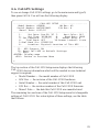
4.4 UPS Characteristics 22
With Smart-UPS and Matrix-UPS 22
With Symmetra Power Array 25
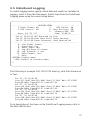
4.5 Data/Event Logging 27
4.6 Call-UPS Settings 29
4.7 Paging Setup 32
4.8 Measure-UPS Info 36
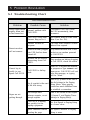
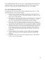
5 Problem Resolution . . . . . . . . . . . . . . . . . . 38
5.1 Troubleshooting Chart 38
5.2 If Problems Persist 39
6 Specifications . . . . . . . . . . . . . . . . . . . . . . . 40
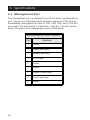
6.1 Management Port 40
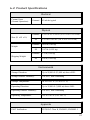
6.2 Product Specifications 41
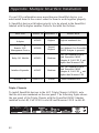
Appendix:
Multiple Smart Slot Installation . . . . . . . . . 42
Triple Chassis 42
Symmetra Power Array 43
Daisy Chains 43
Smart-UPS ans Matrix-UPS 43

1
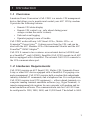
1 Introduction
1.1 Overview
American Power Conversion’s Call-UPS II is a remote UPS management
device that allows you to monitor and control your
APC UPS by modem.
It provides the following features:
• Remote
UPS status display
• Remote
UPS control (e.g., safe reboot during power
outage or when the server is down)
• Data and event logging
• Operator paging in case of trouble
Call-UPS II works with any
APC Smart-UPS
TM
, Matrix-UPS
TM
or
Symmetra
TM
Power Array
TM
. It draws power from the UPS, and can be
used with the
APC Measure-UPS
TM
Environmental Monitor and the APC
PowerNet
TM
SNMP Adapter
TM
.
Call-
UPS II comes in two versions: as an external device (AP9208) and
as a SmartSlot
TM
card (AP9608). SmartSlot Call-UPS II mounts in all APC
devices equipped with a SmartSlot. The external Call-UPS II connects to
the
UPS communications port.
1.2 Hardware Requirements
Call-UPS II requires an APC Smart-UPS, Matrix-UPS, Symmetra Power
Array or other
APC device equipped with a SmartSlot. For paging or re-
mote management, Call-
UPS II requires both a modem that understands
industry standard
AT commands, and a telephone line. For configuration,
Call-
UPS II requires local DTE equipment — either a dumb terminal or a
computer running terminal emulation software (e.g., HyperTerminal). A
remote management site requires its own computer with modem and ter-
minal emulation software. The communications rate for Call-
UPS II can
be configured to 1200, 2400, 9600, and 19,200 baud. The default is
9600.

2
2 Product Description
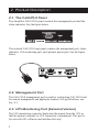
2.1 The Call-UPS II Panel
The SmartSlot Call-UPS II panel contains the management port and the
status indicator. See the figure below.
Management Port
Status
AP9608 Call-UPS Remote Mgt Device
Smart SlotSmart Slot
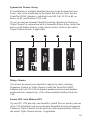
The external Call-UPS II rear panel contains the management port, status
indicator,
UPS monitoring port, and optional power jack. See the figure
below.
2.2 Management Port
The Call-UPS II management port is used for configuring Call-UPS II and
for remote management and paging by modem. For specifications, see
Sec. 6.1.
2.3 UPS Monitoring Port [External Version]
The UPS monitoring connector duplicates the signals from the UPS so
that the normal computer-to-
UPS connection is maintained. This port is
for use with
APC software and interface kits only.

3
2.4 UPS Cable [External Version]
Use this cable to connect Call-UPS II to an APC Smart-UPS, Matrix-UPS,
Symmetra Power Array or other
APC smart device (Share-UPS or Triple
Chassis, for example).
2.5 Power Port [External Version]
The external version of Call-UPS II has a power port for an optional
power adapter. This adapter is not needed in most situations. Call-
UPS II
normally receives power from the UPS through the UPS connection cable,
giving Call-
UPS II protection from poor power conditions. After UPS
shutdown for low-battery condition, Call-UPS II will still draw power
from the
UPS for a time determined by the size of the load and the capac-
ity of the
UPS. However, Call-UPS II stops drawing power from the UPS
before the battery is completely drained.
To determine whether a power connector will be useful, refer to the two
paragraphs that follow. You can obtain a power adapter by contacting
APC technical support at one of the numbers given on the back cover of
this manual. The
APC part number for the power adapter is AP9505.
With Smart-UPS
The optional power adapter is required for some older Smart-UPS models
that do not supply power to Call-
UPS II. To determine whether your
Smart-
UPS supplies power to Call-UPS II, refer to the Smart-UPS user
manual. Plug the adapter into a wall receptacle if you want remote turn-
on and turn-off capability; otherwise, plug it into a Smart
-UPS receptacle.
(Smart-
UPS models 250, 370, and 400 cannot be turned on or off by
remote connection; for these models plug the adapter into a Smart-
UPS
receptacle.)
With Matrix-UPS
You will need the optional power adapter for use with Matrix-UPS only
if you want remote turn-on capability. Matrix-
UPS can be turned off
remotely by Call-
UPS II, but, without the adapter, Call-UPS II will then
lose power. The
UPS will execute a Graceful Reboot command (item 5 on
the
UPS Control menu of Call-UPS II ) without causing Call-UPS II to lose
power. Plug the power adapter into a wall receptacle if you want remote
turn-on and turn-off capability. Otherwise, plug it into a Matrix-
UPS
receptacle.

4
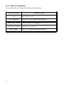
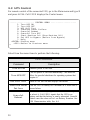
2.6 Status Indicator
The status indicator shows the following conditions.
STATUS LED INDICATION
Off Call-UPS
II
is off.
On Continuously Call-UPS
II
is on with no user logged in.
Single short flashes User is logged in or logging in.
Double short flashes Lockout is in progress.
Rapid flashes Call-UPS
II
failed its power on self-test.

5
3 Installation and Setup
3.1 Handling
Call-UPS II is sensitive to electrostatic discharge. It is shipped in a con-
ductive bag to help dissipate damaging static charges. Leave the product
in the bag until ready to install. Handle Call-
UPS II by the end plate only.
Do not touch the printed circuit board or other components.
3.2 Receiving Inspection
Once the Call-UPS II has been removed from its shipping container,
inspect it for damage that may have occurred while in transit. Notify
the carrier and place of purchase immediately if any damage is found.
The packing materials are recyclable and should be disposed of properly.
Please complete and return the enclosed warranty card.
Call-
UPS II is shipped with a null modem cable (APC part number 940-
0103).
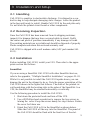
3.3 Installation
Before installing Call-UPS II, install your UPS. Then refer to the appro-
priate section that follows.
SmartSlot
If you are using a SmartSlot Call-UPS II with other SmartSlot devices,
refer to the appendix, “Multiple SmartSlot Installation” on pages 42–43.
While it is not possible to install the Call-
UPS II upside down, you can
damage the unit in the attempt to do so. Note the proper orientation of the
Call-
UPS II shown in the figure that follows. The sides of the printed cir-
cuit board align with the locating slots in the sides of the SmartSlot. In a
UPS, the SmartSlot may be oriented horizontally or vertically.
Use the following procedure to install the Call-
UPS II:
1 Shut down the protected loads and turn off the UPS.
2 Use a #2 Phillips head screwdriver to remove the two screws re-
taining the cover. Keep the screws handy for step 4 below. Retain
the cover for future use.
3 Orient the Call-
UPS II to fit in the SmartSlot as shown below.
Slide the Call-
UPS II all the way into the SmartSlot. The panel of
the Call-
UPS II should be flush with the front face of the slot.

6
4 Secure the Call-
UPS II with the screws removed in step 2.
5 Turn on the
UPS and the protected equipment.
External Version
It is not necessary to turn off the the UPS or its load before connecting or
disconnecting the external Call-
UPS II. When connected, Call-UPS II may
cause the
UPS to beep, or, if the UPS is powered off, to power on. This is
normal.
If a device such as a server or workstation is currently using the communi-
cations port on the back of the UPS, disconnect it now according to the
UPS connection instructions. Connect that device securely to the UPS
Monitoring Port on Call-UPS II. See Sec. 2.5 to determine if the optional
power adapter is required.
3.4 Confirm Operation
Observe the status indicator on Call-UPS II. After a moment it should
be on continuously. If the indicator flashes rapidly, Call-
UPS II has failed
its power-on self-test. See Chapter 5.
Use only
APC-supplied cables to connect the external version
of Call-
UPS II to the UPS. Do not connect to any Call-UPS II port
except as specified in these instructions. Connections using a
cable or any other manufacturer may cause damage to or
improper operation of Call-
UPS II, the UPS, or the computer.

7
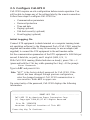
3.5 Configure Call-UPS II
Call-UPS II requires on-site configuration before remote operation. You
will be able to change any of the settings later by the remote connection.
Follow these steps to configure Call-
UPS II for:
• Communication parameters
• Password protection
• Time and date
• Paging (optional)
• Dial-back security (optional)
• Event logging (optional)
Initial Logging On
Connect DTE equipment (a dumb terminal or a computer running termi-
nal emulation software) to the Management Port of Call-
UPS II using the
supplied null modem cable. It may be necessary to use an adapter (not
supplied) to connect the
DTE equipment to the null modem cable.
Set the communication parameters of the DTE equipment to
9600 bits per
second, 8 data bits, no parity, and 1 stop bit (
9600, 8, N, 1).
With Call-
UPS II running (Status Indicator on steady), press CTRL + P
(press and hold the CTRL key while pressing the P key). At the prompt:
Enter Password>
Type in APC and press ENTER.
Note: “
APC” is the factory default password for Call-UPS II. If the
default has been changed through previous configuration,
enter the changed password. Call-
UPS II communication is
case sensitive. Enter
APC in upper case.
On correct entry of the password, Call-
UPS II displays the following
information:
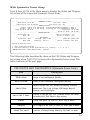
---------------------- SMART-UPS 700 --------------------
Call-UPS II by American Power Conversion Corp
(c) Copyright 1994,95,97 All Rights Reserved
Site ID: 12345678
Location: Physical Location of This UPS
Press Any Key To Continue...

8
Note the top line, which displays the model number of the
UPS that is
currently connected . Site
ID and Location are user configuration items.
The display shows the factory defaults.
Press any key to bring up the Main menu:
---------------------- MAIN MENU ------------------------
Date: Dec-16 '97 Time: 08:39:36
1- UPS Status
2- UPS Control
3- UPS Characteristics
4- Data/Event Logging
5- Call-UPS Settings
6- Paging Setup
7- Measure-UPS Info
?- Help
<ENTER> Display Menu
<ESC> End Session
>
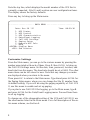
Customize Settings
From the Main menu, you can go to the various menus by pressing the
number associated with each of them. Press 5, then
ENTER to bring up
the Call-
UPS Settings menu. Set the date, time, password, location, and
baud rate from this menu. The baud rate should be set at
9600. The other
menu items can be left alone for now. Note that any changes you make
are displayed when you return to the menu.
Then press
ESC to return to the Main menu. Type 6 and press ENTER for
the Paging Setup menu, where you can change the Site
ID number from
its default setting. If you will be using the paging capability of Call-
UPS
II, use this menu to enable and set up paging.
If you plan to use Call-
UPS II for logging, go to the Main menu, type 4
and press
ENTER for the Data/Event Logging menu. Proceed from there
to set up logging.
To change any of the changeable setting of the UPS and Call-UPS II, use
the other menus listed in the Main menu. For a full description of the en-
tire menu scheme, see Section 4.

9
Any changes to Call-
UPS II communication settings are held until the end
of the session. Changes are made when Call-
UPS II issues modem com-
mands at that time.
Connect to Modem
Call-UPS II requires a modem for remote UPS control and paging. If a
modem is used with Call-
UPS II, some thought must be given to powering
it. Plugging the modem into the protected power output of the
UPS will
keep the modem operating in bad power conditions, but remote turn-on
of the
UPS will not be possible since, when the UPS is off, the modem
is off. By plugging the modem into a wall socket, remote turn-on of the
UPS will work, but the modem will have to get by with unprotected
power. Also, it is possible in this situation to miss pages, since the
modem would be off in a power outage that Call-
UPS II tries to report by
paging.
A better option is to use a modem designed for portable computers that
draws power from the computer. Call-
UPS II will power such a modem,
providing protected power whether the
UPS is on or off. Be careful to use
a modem that draws power from Call-
UPS II, not a battery.
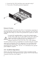
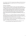
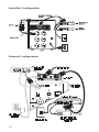
The configuration is complete. Disconnect the management device from
Call-UPS II. Connect the Call-UPS II according to the appropriate system
connection diagram on the following page.
Note: Use a standard modem cable to make this connection. Do not
use the null modem cable supplied with Call-
UPS II.

10
SmartSlot Configuration
External Configuration

11
4 Operation
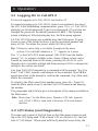
4-1 Logging On to Call-UPS II
For on-site logging on to Call-UPS II, see Section 3.5.
For remote logging on to Call-
UPS II, connect via modem to the site of
the
UPS. After establishing communication, press CTRL + P. Call-UPS II
prompts you for the password. Type in your password. (If you have not
changed the password, the default password is
APC.) The Opening
screen is diplayed. After pressing any key, the Main menu appears.
All Call-UPS II functions are available from the Main menu. To gain
access to one of the listed functions, type the associated number and
press
ENTER. To redraw the screen, press ENTER by itself.
Tip: Extensive online help is available throughout the menu
system. It is available whenever a “?” appears on a menu.
The “>” is the Call-
UPS II menu prompt. Call-UPS II uses the double
prompt “>>” to request a settable value. Some of these values can be
viewed by selecting them on the menu, pressing
SPACEBAR to cycle
through a list of possible settings and then pressing
ENTER to change the
setting to the current one listed.
Any time Call-UPS II responds to a command with the prompt “Are You
Sure?” Call-
UPS II requires confirmation of the command. Type YES in
uppercase letters at the prompt to confirm the command. Any other entry
aborts the command.
To return to the Main menu from another menu, press
ESC. Press ESC
from the Main menu screen to end the Call-UPS II session and hang up
the modem.
The paragraphs which follow give a description of the menus available in
the Main menu.
Note: Menu item 7 on the Main menu, Measure-
UPS Info, appears
only if Call-
UPS II is used with a Measure-UPS environment
monitor.
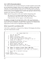
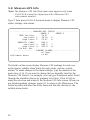
4.2 UPS Status [and Diagnostics]
The name and content of the first item on the Main menu varies accord-
ing to the UPS being used. With a Smart-
UPS or a Matrix-UPS, the first
item is “
UPS Status.” When used with the Symmetra Power Array, the

12
first item is “UPS Status and Diagnostics.” Refer to the appropriate
sections and accompanying tables that follow.
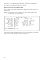
With Smart-UPS and Matrix-UPS
Type 1, then ENTER at the Main menu to display the status of the con-
nected UPS.
Note: This example is from a Matrix-
UPS 3000. Other models may
not show this exact information.
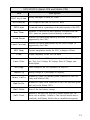
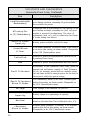
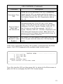
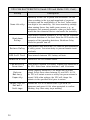
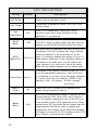
The following table describes the items on the
UPS Status screen when
Call-
UPS II is used with Smart-UPS or Matrix-UPS.
------------------ MATRIX 3000 STATUS -------------------
Utility Line: 241.2 VAC Battery Info
UPS Output: 235.6 VAC ------------------
UPS Load: 000.0 % Voltage: 55.62 VDC
Run Time: 0185 min Capacity: 100.0 %
Load Power: 000.0 VA Smart Cells: 002
Load Current: 00.00 A Bad Cells: 000
UPS Temp: 019.8 C Batt Date: 02/23/97
Freq: 60.00 Hz Self Test: OK
Last Xfer: Test
Status: On-Line
<ESC>=Main menu>

13
UPS STATUS (Smart-UPS and Matrix-UPS)
Item Description
Utility Line
Utility line input, in volts AC RMS.
UPS Output
UPS output to the load, in volts AC RMS.
UPS Load
Connected load as a percentage of the rated capacity of the UPS.
Run Time
Estimate of the total run time currently available from the
UPS, based on present load and battery, in minutes.
Load Power
Amount of power being drawn by the load, in volt-amps (if
supported by the UPS).
Load Current
Amount of current being drawn by the load, in amps (if
supported by the UPS).
UPS Temp
Current temperature inside the UPS, in degrees Celsius.
Freq
Output frequency of the UPS, in hertz.
Last Xfer
Reason for the last UPS transfer to battery. Possible results
are: Test, Low Voltage, Hi Voltage, Rate of Change, and
Notch/Spike.
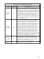
Voltage
Total voltage of the UPS batteries, in volts DC.
Capacity
Battery charge as a percentage of capacity.
Smart Cells
Number of Smart Cell battery packs connected to the UPS
(only with Matrix-UPS).
Bad Cells
Number of Smart Cells connected to the UPS that have gone
bad (only with Matrix-UPS).
Batt Date
Date of the last battery change.
Self Test
Results of the last UPS self-test. Possible results are: OK,
None (not available), Unable to Test (invalid results due to
overload), and Battery Failed (due to insufficient capacity).

14
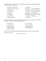
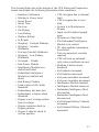
The following fault conditions display only when Call-
UPS II is used with
a Matrix-
UPS and a fault condition exists.
• Runtime Calibration
• Waiting to Power Load
• Smart Boost
• Smart Trim
• On-Line
• On-Battery
• Low Battery
• Replace Battery
• In Bypass
• Sleeping – Delayed Wakeup
• Sleeping – Inverter Shutdown
• Forcing Graceful Shutdown
• Sleeping – Low Battery
• Shutdown Overload – Unable
to Transfer to Battery
• UPS Fault
The Status line at the bottom of the Status screen can display the follow-
ing
UPS status conditions:
If the
UPS is powered off during a status request, Call-UPS II responds
with the message:
UPS Powered OFF
• Main Relay
• Batt Charger
• Bypass Relay
• Internal Temp
• Elec Unit Fan
• Iso Unit Fan
• Bypass Supply
• Voltage Select
• DC Imbalance

15
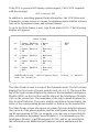
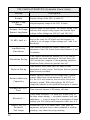
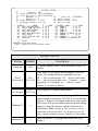
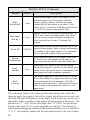
The following table describes the items on the
UPS Status and Diagnos-
tics screen when Call-
UPS II is used with a Symmetra Power Array. The
table continues on the next page.
With Symmetra Power Array
Type 1, then ENTER at the Main menu to display the Status and Diagnos-
tics screen of the connected Symmetra Power Array.
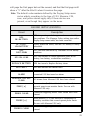
UPS STATUS AND DIAGNOSTICS (Symmetra Power Array)
Item Description
IM Status
Status of the Intelligence Module.
RIM Status
Status of the Redundant Intelligence Module.
Last Xfer
Reason for the last UPS transfer to battery. Possible
results are: Test, Low Voltage, HiVoltage, Rate of
Change, and Notch/Spike.
Last Self Test
Results of the last Self Test. Possible results are listed
in earlier Self Test Table in this section.
Input
Utility line input, in volts AC RMS and in hertz.
Output
UPS output to the load, in volts AC RMS and in hertz.
Load Current
Amount of current being drawn by the load, in amps.
----------------------------- SYMMETRA STATUS -------------------------------
IM Status: On & Ok Last Xfer: None
RIM Status: Off & Failed Last Self test: OK
------------------------------ INPUT/OUTPUT ---------------------------------
Input: 246.0 V at 60.04 Hz Load Assuming No Redundancy: 000 %
Output: 000.0 V at 60.04 Hz Allowing for n+1 Redundancy: 000 %
Load Current: 00.0 A Capacity: 16.0 kVA
Alarm if Over: 06.0 kVA
----------------------------- POWER MODULES ---------------------------------
Installed: 05 Fault Tolerance: n+0
Bad: 00 Alarm if Under: n+2
------------------------------- BATTERIES -----------------------------------
Installed: 004 Voltage: 137.1 VDC Runtime: 0244 min.
Bad: 000 Capacity: 98.0 % Alarm if Under: 015 min.
System Status:On-Line
1- Main Frame Information
2- External Battery Frame Information for frame(s): 1, 2, 3, 6, 7
<ENTER>=Refresh, <ESC>=Main menu>, ?=Help>

16
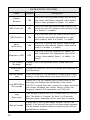
UPS STATUS AND DIAGNOSTICS
(Symmetra Power Array, Continued)
Item Description
Load Assuming No
Redundancy
Connected load as a percentage of the capacity of the
good battery modules, assuming all good modules
are available for power.
Allowing For
n+[1] Redundancy
Connected load as a percentage of the capacity of the
good battery modules, assuming one [two, no] good
module is reserved for redundancy. The value of
redundancy (n+0, n+1, n+2) is taken from the Alarm
if Under setting (see below).
(Battery Power)
Capacity
Battery power available, in kilovolt-amps.
(Load)Alarm
if Over
Load alarm threshold, in kilovolt-amps. If the load is
at or above this setting, an alarm sounds. Changeable
in the UPS Characteristics menu.
Installed
Number of power modules/batteries installed in the
Symmetra Power Array.
Bad
Number of power modules/batteries that have failed.
Fault Tolerance
Redundancy of the Symmetra Power Array, given the
present load and battery capacity. A Fault Tolerance
of n+2, for example, means that two modules could
fail and there would be enough power for the load in
the event of utility line power outage.
(Fault Tolerance)
Alarm if Under
Low redundancy alarm. If the Fault Tolerance goes
below this setting, an alarm sounds. Changeable in
the UPS Characteristics menu.
Voltage
Total voltage of the batteries, in volts DC.
(Battery Charge)
Capacity
Battery charge as a percentage of capacity.
Runtime
Estimated runtime on-battery with the present load,
based on the latest Run Time Calibration (Sec. 4.3).
(Runtime)
Alarm if Under
Runtime alarm threshold, in minutes. If the Runtime
reading falls below this setting, an alarm sounds.
Changeable in the UPS Characteristics menu.
Page is loading ...
Page is loading ...
Page is loading ...
Page is loading ...
Page is loading ...
Page is loading ...
Page is loading ...
Page is loading ...
Page is loading ...
Page is loading ...
Page is loading ...
Page is loading ...
Page is loading ...
Page is loading ...
Page is loading ...
Page is loading ...
Page is loading ...
Page is loading ...
Page is loading ...
Page is loading ...
Page is loading ...
Page is loading ...
Page is loading ...
Page is loading ...
Page is loading ...
Page is loading ...
Page is loading ...
Page is loading ...
Page is loading ...
Page is loading ...
Page is loading ...
Page is loading ...
-
 1
1
-
 2
2
-
 3
3
-
 4
4
-
 5
5
-
 6
6
-
 7
7
-
 8
8
-
 9
9
-
 10
10
-
 11
11
-
 12
12
-
 13
13
-
 14
14
-
 15
15
-
 16
16
-
 17
17
-
 18
18
-
 19
19
-
 20
20
-
 21
21
-
 22
22
-
 23
23
-
 24
24
-
 25
25
-
 26
26
-
 27
27
-
 28
28
-
 29
29
-
 30
30
-
 31
31
-
 32
32
-
 33
33
-
 34
34
-
 35
35
-
 36
36
-
 37
37
-
 38
38
-
 39
39
-
 40
40
-
 41
41
-
 42
42
-
 43
43
-
 44
44
-
 45
45
-
 46
46
-
 47
47
-
 48
48
-
 49
49
-
 50
50
-
 51
51
-
 52
52


Ask a question and I''ll find the answer in the document
Finding information in a document is now easier with AI
Related papers
Other documents
-
American Power Conversion AP9207 User manual
-
CyberPower PR750LCDN User guide
-
-
-
Schneider Electric AP9630 User manual
-
Black Box Laptop AP9608 User manual
-
-
-
-