Page is loading ...

GRO-575B / GRO-575M
REVERSE OSMOSIS WATER FILTRATION SYSTEM
INSTALLATION AND OPERATION MANUAL
©2018 Pentair Residential Filtration, LLC waterpurification.pentair.com
FDF1-RCFDF1-RC
GRO75-RC
F2B1-RC F2B2-RC F2B1-RC F2B2-RCF1GC-RC
FDF1-RC
GRO75-RC
F1GC-RC

FreshPoint GRO-575B, GRO-575M
Filtration System
INSTALLATION INSTRUCTIONS
English ................................Pages 3-18
Repair Parts ...........................Pages 15-16
FreshPoint GRO-575B, GRO-575M
Sistema de filtración
INSTRUCCIONES DE INSTALACIÓN
Español ............................. Páginas 19-34
Piezas de repuesto ................... Páginas 31-32
FreshPoint GRO-575B, GRO-575M
Système de filtration
DIRECTIVES D'INSTALLATION
Français .............................. Pages 35-50
Piéces de Rechange ....................Pages 47-48
FDF1-RCFDF1-RC
GRO75-RC
F2B1-RC F2B2-RC F2B1-RC F2B2-RCF1GC-RC
FDF1-RC
GRO75-RC
F1GC-RC

IMPORTANT: Before installing this reverse osmosis system,
make certain your water supply complies with the following
operating specifications. Failure to do so may reduce the
effectiveness of the system and will void the warranty.
SPECIFICATIONS
Pressure Range: 40 to 100 psi (2.75–6.89 bar)
Temperature Range: 40–100°F (4.4–37.8°C)
TDS: <2000 ppm
Maximum Hardness
†
: <10 gpg (170 mg/L)
Sulfide, Iron and Manganese
‡
: <0.1 ppm
Chlorine in Water Supply: <2 ppm
pH Limits: 3–11
Overall Dimensions: 17.82"W x 5.46"D x 12.54"H
(453mm x 139mm x 319mm)
Weight: 10.7 lbs (4.8 kg)
Tank Dimensions: 10.91"DIA x 14.61"H
(277mm DIA x 371mm)
Tank Capacity Max: 3.2 gal (12.1 L)
Tank Air Pressure Empty: 5-7 psi (0.34-0.48 bar)
Tank Weight (Full): 25.50 lb (11.6 kg)
†
If the hardness of your water is above 10 gpg (171 mg/L), lime
scale will build up rapidly on the membrane. Scale buildup will
plug the membrane and make the system ineffective. We do not
recommend these reverse osmosis systems to be used with
water in excess of 10 gpg (171 mg/L) hardness.
‡
A maximum total level of approximately 0.01 ppm sulfide, iron
or manganese is permissible. See your local dealer to reduce
these substances in your water.
PARTS INCLUDED:
• System with cartridges
• Storage Tank
• Installation Hardware Kit
• Lead-free drinking water faucet with air gap
CALIFORNIA PROPOSITION 65 WARNING
WARNING:
This product contains chemicals known to the
State of California to cause cancer or birth
defects or other reproductive harm.
Tools and Materials Required
• Hand or electric drill (cordless preferred)
• (2) Adjustable wrenches
• Slotted and Phillips screwdrivers
• File
• Safety glasses
• Drill bits: 1/8", 3/16", 1/4", 3/8"
• Tube cutter or utility knife
• Pencil
• Towel
• Bucket
• Screwdriver bits: 1/8", 3/16", 1/4", 3/8"
If sink does not have hole for separate faucet:
• Center punch
• 3⁄4" hole saw or drill bit
• Safety mask
NOTE: All tools may not be necessary for installation. Read
installation procedures before starting to determine
what tools are necessary.
FRESHPOINT GRO-575B/GRO-575M Installation and Operation Manual • 3

GENERAL
WARNING:
Do not use with water that is microbiologically
unsafe or of unknown quality without adequate
disinfection before or after the system.
Systems certified for cyst reduction* may be
used on disinfected waters that may contain
filterable cysts.
*NSF/ANSI Standard 53 and 58 certified to reduce cysts such
as Cryptosporidium and Giardia by mechanical means.
CAUTION
RO System must be protected against freezing,
which can cause cracking of the RO components
and water leakage.
NOTE:
• Your water must be within required limits for satisfactory
operation. If not, your membrane life may be shortened and
your warranty will be voided (see Specifications on page 3).
• This reverse osmosis system will not protect against
disease-causing bacteria or remove naturally-occurring
harmless bacteria.
• Install on cold water line only.
• Make certain that installation complies with all state and
local laws and regulations.
• The replacement cartridges and reverse osmosis element
included with this system have limited service lives. Changes
in taste, odor, and color of the water being filtered indicate
that the cartridge should be replaced.
• After prolonged periods of non-use (such as during a
vacation) it is recommended that the system be flushed for 5
minutes before it is used.
• A drinking water cartridge may contain carbon fines (very
fine black powder). After installation, flush the system for 5
minutes to remove the carbon fines before using the water.
• It is recommended that you run the tap at least 20 seconds
prior to using water for drinking or cooking purposes.
• The contaminants or other substances removed or reduced
by this water treatment device are not necessarily present in
your water.
HOW REVERSE OSMOSIS WORKS
The GRO-575B/GRO-575M Reverse Osmosis (RO) System uses
a semi-permeable membrane to reduce dissolved salts and
minerals, improving the taste and odor of your water. The RO
membrane is made of layers of micron-thin film wound around
a hollow center core. Water molecules can pass through the
membrane, but dissolved salts and minerals are rejected.
The GRO-575B/GRO-575M Reverse Osmosis System features
5-stage filter action. Your water supply is pre-filtered to
reduce dirt and chlorine that may foul the membrane. The RO
membrane separates this pre-filtered water into PRODUCT
WATER and DRAIN or REJECT WATER. Incoming water
pressure forces the product water through the membrane and
into the storage tank. Dissolved solids and other contaminants
cannot pass through the membrane and are sent to the drain
as reject water. When you open the drinking water faucet,
product water is drawn from the storage tank through an
activated carbon post-filter, providing you with cleaner, great-
tasting water.
For each gallon of water produced, several gallons are
discharged as reject water. The storage tank can hold up to
2.1 gallons (7.9 L) of water at a time, for drinking and cooking
needs. When used under the Specifications on page 3 of the
manual, your Reverse Osmosis membranes should last 12-24
months.
PRECAUTIONS
4 • FRESHPOINT GRO-575B/GRO-575M Installation and Operation Manual

1
INSTALLATION
• Please read all instructions and precautions before installing and using
your GRO-575B/GRO-575M.
• For standard, under-sink installation on 3/8" (9.52 mm) steel, brass, or
copper cold water line.
• When selecting a mounting location of the system and tank, take into
consideration the length of tubing required for connections between existing
plumbing and system components. Some installation sites may require
more tubing than provided in the kit.
• Numbered diagrams correspond with numbered steps.
1. Installing the Water Supply Adapter
The supply adapter fits 1/2"-14 NPS supply threads or
3/8" x 3/8" compression. If local codes permit, it may be used to connect the
system to the cold water supply line. If local codes do not permit the use of the
supply adapter, alternate connectors can be obtained from your local supplier.
Directions:
(A) Turn off cold water supply line. If cold water line does not have a shut-off
valve under the sink, you should install one.
(B) Turn on the cold water faucet and allow all water to drain from line.
(C) Disconnect riser cold water supply valve.
(D) Ensure the sealing gasket is fully seated into the feed adapter valve female
thread.
(E) Install feed adapter valve onto supply valve as desired. The feed adapter valve
may be installed at the bottom of the supply hose or the top of the cold water
line. Hand tighten only.
(F) Connect the riser to the feed adapter valve.
NOTE: Be careful not to cross-thread..
The 1/4" red drain tubing includes a
ow controller installed in one end of
the tubing. The end of the tubing
with the ow restrictor must be
installed into the RO system before
attaching to the faucet.
DO NOT cut o the ow restrictor.
WARNING:
CONNECT TO WATER
SUPPLY LINE
DRAIN PIPE
FAUCET DRAIN LINE (3/8" RED)
RO OUTLET LINE (3/8” BLUE)
RO INLET LINE (3/8” WHITE)
RO DRAIN LINE (1/4" RED)
RO LINE TO TANK (3/8” BLUE)
FRESHPOINT GRO-575B/GRO-575M Installation and Operation Manual • 5

INSTALLATION CONTINUED . . .
2. Selecting the Faucet Location
The drinking water faucet should be positioned with function, convenience, and
appearance in mind. An adequate flat area is required to allow faucet base to rest
securely. The faucet fits through a 3/4" hole. Most sinks have pre-drilled 1-3⁄8" or
1-1⁄2" diameter holes that may be used for faucet installation. If these pre-drilled
holes cannot be used or are in an inconvenient location, it will be necessary to
drill a 3/4" hole in the sink to accommodate the faucet.
CAUTION
This procedure may generate dusts which can cause severe irritation if
inhaled or come in contact with the eyes. The use of safety glasses and
safety mask for this procedure is recommended.
CAUTION
DO NOT ATTEMPT TO DRILL THROUGH AN ALL-PORCELAIN SINK. If
you have an all-porcelain sink, mount the faucet in pre-drilled sprayer
hole or drill through countertop next to sink.
CAUTION
When drilling through a countertop, make sure the area below the
drilled area is free of wiring and piping. Make certain that you have
ample room to make the proper connections to the bottom of the
faucet.
CAUTION
Do not drill through a countertop that is more than 1" thick.
CAUTION
Do not attempt to drill through a tiled, marble, granite or similar
countertop. Consult a plumber or the countertop manufacturer for
advice or assistance.
The following instructions apply to stainless steel sinks ONLY.
(A) Line bottom of sink with newspaper to prevent shavings, parts or tools from
falling down the drain.
(B) Place masking tape over the area to be drilled to help prevent scratches if
drill bit slips.
(C) Mark point with center punch. Use a 1/4" drill bit to drill a pilot hole through
sink.
(D) Use a 1-
1
⁄4" hole saw to enlarge hole. Smooth rough edges with a file.
3. Mounting the Faucet
WARNING:
Due to variance in installation sites, it is highly recommended to
install the 1/4" red drain tubing to the RO system manifold before
fully mounting the faucet. Make note of the 1/4" red drain tubing
length required to reach from the RO system manifold to the
faucet connection and plan accordingly in relation to mounting
location of system components. Furthermore, the 1/4" red drain
tubing includes a flow controller installed in one end of the
tubing. The end of the tubing with the flow restrictor must be
securely installed into the RO system manifold before attaching to
the faucet. DO NOT cut off the flow restrictor.
NOTE: Not all parts provided with the faucet may be needed for installation.
(A) Slide chrome plate and black rubber washer onto faucet by threading both
drain tubes through the holes on the plate and washer.
(B) Attach large diameter red 3/8" drain tube to barb fitting at the faucet base.
This tube should be long enough to reach the drain clamp in Step 4.
(C) Locate the small diameter red 1/4" drain tube connected to the drain port
of the GRO element. Route the tubing to the faucet and cut off the excessive
length of tubing.
(D) Slide white extension spacer onto long threaded section of faucet. Open end
of extension should come in contact with base of faucet.
(E) Screw washer, lockwasher, and locking nut onto end of faucet threads
(F) Screw quick connector onto end of facuet threads.
(G) Wet end of 3/8" blue tube. Push into bottom of quick connector. Tug gently to
be sure connection is complete.
NOTE: To remove the tube, push on the fittings' collar and pull the tube out.
(H) Holding the faucet, feed the three tubes through the hole in the sink. Position
the faucet handle at a desired location
(I) Center the faucet and slip slotted disc between the white extension spacer
and the bottom of the counter or sink. Tighten the locking nut with a wrench
until it is tight.
D
C
1
⁄
4”
1
1
⁄4”
A
B
C
D
Pilot Hole
Mounting
Hole
1
1
⁄4"
1/4"
2
CHROME PLATE
SLIP SLOTTED DISC
COUNTER TOP
WASHER
LOCKWASHER
LOCKING NUT
QUICK CONNECTOR
BARB FITTING
(3/8” RED FAUCET DRAIN LINE)
TUBING (3/8” BLUE RO OUTLET LINE)
BARB FITTING
(1/4” RED RO DRAIN LINE)
BLACK RUBBER WASHER
WHITE EXTENSION SPACER
3
C
B
A
A
I
D
E
H
F
G
6 • FRESHPOINT GRO-575B/GRO-575M Installation and Operation Manual

4. Installing the Drain Clamp
NOTE: If you have a single-basin sink with a disposal unit, call Technical Support
for options.
NOTE: Before installing the drain clamp, check the drainpipes under the sink
for corrosion. Corroded pipes should be replaced before continuing with
installation.
(A) Attach the drain clamp to a vertical section of the drainpipe, about 6" above
the trap. Make sure the opening on the drain clamp is facing towards the
drinking water faucet.
(B) Using the fitting hole of the drain clamp as a guide, drill a 1/4" hole through
one side of the drainpipe.
(C) Remove the drain clamp from the drainpipe and enlarge the hole with a
3/8" drill bit. Use a file to remove rough edges from the drilled hole.
(D) Make sure the black rubber gasket is adhered to the inside of the drain clamp
and place the drain clamp assembly over the drilled hole. Look through the
hole and position the clamp so that the center of the clamp hole is slightly
higher (about 1/16") than the center of the drilled hole. Tighten the clamp
securely.
(E) Screw the plastic compression nut onto the drain clamp until hand-tight.
5. Connecting the Faucet to the Drain
CAUTION
This is a gravity drain line. Any loops, kinks or sharp bends must be
eliminated before proceeding. Failure to create a straight line to the
drain may result in reject water leaking through the air gap in the
faucet onto the countertop and below the faucet.
(A) Align the larger reject 3/8" red tubing from the faucet with the compression
nut on the drain clamp. Create as straight and smooth a path as possible with
the tubing. Do not kink tube. Cut the tubing squarely and remove any internal
and external burrs. Insert inner tube insert (white cone) into end of 3/8" red
tubing. Remove compression nut from the drain clamp. Place compression
nut on end of 3/8" red tubing.
(B) Insert the tubing into the drain port until it stops. Tighten the compression nut
with fingers, then tighten 1 to 2 turns with a wrench to secure tubing to drain
port.
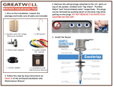
6. Mounting the System
WARNING:
When selecting a mounting location of the system and tank, take
into consideration the length of tubing required for connection
between components. Some installation sites may require more
tubing than provided in the kit.
(A) Select a location under the sink, or other suitable area where the system will
be installed.
NOTE: The system carton can be used to determine the operational footprint
required for installation of the system and replacement cartridges.
(Figure 6)
(B) Mount the system vertically. Ensure mounting is level. Remove filter
cartridges for easier access to bracket mounting holes. Place a pencil mark
in the upper slots of the bracket mounting holes. (Figure 4b). Alternate
mounting option: If mounting the system near the floor, place the pencil
marks above each of the mounting holes on the bracket to ensure enough
space resides below the cartridge and the floor for cartridge replacement
(Figure 4c). Use the 3/32" drill bit to create pilot holes for mounting.
WARNING:
The system should be mounted to a firm, solid surface that is
able to support the weight of the system.
7. Connecting the Faucet to the System
(A) Determine the length of plastic blue tubing needed to connect to the outlet
(right) side of the filter from the faucet. Be sure to allow enough tubing to
prevent kinking and cut the tubing squarely. Use a marker to mark one end of
the tubing 5/8" from the end. Wet the end of the 3/8" tube and push into the
outlet (right) connection of the system up to the mark.
CAUTION
Do not bend or crimp tube while inserting.
(B) Gently pull back on the tube to ensure it is connected properly.
4
A
B C
6"
D
E
5
A
B
3/8" Tube
7” (178 mm)
16.25”
(413 mm)
20.50”
(521 mm)
6
6
FRESHPOINT GRO-575B/GRO-575M Installation and Operation Manual • 7

7
RO DRAIN LINE
(3/8" RED)
RO LINE TO TANK
(3/8” BLUE)
FAUCET DRAIN LINE (1/4” RED)
RO OUTLET LINE (3/8” BLUE)
RO INLET LINE (3/8” WHITE)
8 • FRESHPOINT GRO-575B/GRO-575M Installation and Operation Manual

INSTALLATION CONTINUED . . .
8. Connecting the Storage Tank to the System
CAUTION
When tank is full, it weighs approximately 19.50 lbs. (8.8 kg.) Provide
ample support under the tank.
(A) To prevent leaks, apply 3 or more wraps of plumber's tape to threads on
tank. Thread the tank valve onto the top of the tank opening. Turn tank so
handle is in line with tubing.
CAUTION
The tank/valve connection will leak if not properly sealed. Plumber's
tape will normally seal the threaded connection.
(B) Locate the 3/8" blue tubing. Place a mark on the tubing 5/8" from one end.
Moisten the marked end of the tubing with water and insert with a twisting
motion into the port of the tank valve until the 5/8" mark is flush with the
quick connect fitting. Then locate the tank near the system's installation
area.
(C) Cut the tubing to correct length. Install free end of tubing into white
quick-connect fitting on the system. Ensure the tubing does not kink. Retain
remaining blue tubing for use in connecting system to water supply adapter.
Some installation sites may require additional tubing not provided in kit.
(D) Place entire system over mounting screws on wall and slide down.
CAUTION
Make certain system is firmly attached to wall to prevent it from falling
and possibly becoming damaged.
NOTE: Use caution not to bend or pinch the tubing behind the system while
attaching to mounting screws.
9. Connecting the System to the Water Supply Adapter
(A) Locate remaining length of 3/8" plastic blue tubing.
(B) Place a mark on the tubing 5/8" from the end. Moisten the end of the tubing
with water and insert with a twisting motion push into white quick connect
fitting on the left side of system. Depending on the installation, the system
may need to be removed from the mounting surface to access the left side of
the system.
(C) Cut the tube to a length that will allow connection to the Water Supply
Adapter. Ensure the tubing does not kink. Place a mark on the tubing
5/8" from the end. Moisten the end of the tubing with water and insert with a
twisting motion push into quick connect fitting on the Water Supply Adapter.
10. Faucet Operation
(A) For controlled water flow, push the handle down.
(B) For constant water flow, lift the faucet handle to lock it in the open position.
8
A
B
3/8" Tube
Apply
plumber's
tape
5/8"
Push Down
Push Up
A
B
10
RO DRAIN LINE
(3/8" RED)
RO LINE TO TANK
(3/8” BLUE)
FAUCET DRAIN LINE (1/4” RED)
RO OUTLET LINE (3/8” BLUE)
RO INLET LINE (3/8” WHITE)
9
FRESHPOINT GRO-575B/GRO-575M Installation and Operation Manual • 9

11. System Start-up
NOTE: The reverse osmosis membrane is treated with a food grade sanitizing
agent that may cause an undesirable taste. Although it is not harmful, it
should be flushed from the system.
NOTE: The post-polishing filter may contain fine black carbon particles. These
fines are harmless, but may make the water appear gray in color. The
carbon fines are flushed from the system with the first tank full of water.
NOTE: The RO system does not produce a high volume of water on demand as an
ordinary filter does. Water is produced at a slow, drop-by-drop rate. The
system requires about 2 to 4 hours to fill the storage tank. As water is
taken from the tank, the system automatically starts the cycle of replacing
the water and then stops water production when the tank is full.
CAUTION
Visually check the entire system for leaks.
If a leak is present, see
Troubleshooting on page 14.
(A) Turn off valve at top of storage tank.
(B) Turn on the cold water supply slightly, and ensure the supply adapter valve is
open.
(C) Lift the faucet handle to lock it in the open position and let it drip for 30 min.
(D) Completely open the cold water supply until it comes to a stop. Allow water
to drip from the faucet for 12 more hours. Then close the faucet and open the
valve on the storage tank. The tank valve is open when the handle lines up
with the tubing connection.
(E) Allow 3 hours for the tank to fill. Continue to periodically check the
installation for leaks. After the storage tank is filled, open the faucet to flush
the post-filter cartridge. Allow 4 to 5 minutes for all of the water to drain from
the tank. Close faucet and allow tank to fill.
(F) Repeat step E four times.
NOTE: Initially, the water may appear cloudy. This is a result of air trapped in
the post-polishing filter. It is not harmful and will disappear in a matter
of minutes. It may take up to a week after installing a new post-polishing
filter for the trapped air to dissipate.
The system is ready for operation. You can now enjoy quality water from your
Reverse Osmosis System.
TESTING YOUR REVERSE OSMOSIS SYSTEM
(NON-MONITORED SYSTEMS ONLY)
Model GRO-575B Reverse Osmosis System
Total Dissolved Solids (TDS) Test
NOTE: It is highly recommended that you (the consumer) have your water
tested at least every 6 months to verify that your system is performing
satisfactorily.
SAMPLING INSTRUCTIONS:
Sampling instructions are included with the Total Dissolved Solids (TDS) Test Kit.
Total Dissolved
Solids Test Kit
11
Closed Tank Valve
Open
Tank Valve
Counter-
clockwise
A
B
10 • FRESHPOINT GRO-575B/GRO-575M Installation and Operation Manual

OPTIONAL INSTALLATION
Connecting your Reverse Osmosis System to Refrigerator Icemaker / Water Dispenser
CAUTION
If you are connecting this unit to your refrigerator/icemaker with initial RO installation, wait to turn on the icemaker
until the post-polishing filter has been flushed according to Step 11.
CAUTION
Use plastic tubing and fittings. Do not use copper tubing or brass fittings.
NOTE:
For optimum performance, it is recommended that the distance between the RO system and the refrigerator icemaker/water
dispenser be no greater than 10 feet (3 m). At distances greater than 10 feet, the water pressure from the system may not be
adequate to deliver water to the refrigerator.
MATERIALS REQUIRED(available from your local hardware store):
• 3/8" x 3/8" x 3/8" (0.952 mm x 0.952 mm x 0.952 mm) compression or quick-connect tee
• 10 feet (3 m) of 3/8" (0.952 mm) polyethylene tubing
• Shut-off valve
1. Turn off refrigerator water supply and icemaker (consult manufacturer’s guidelines).
2. Close tank valve (on top of storage tank).
3. Turn off water to RO system at the cold water supply, or at the feed water supply adapter.
4. Open drinking water faucet to relieve pressure.
5.
Locate tubing (permeate) leading to your drinking water faucet. Cut and insert the
3/8"
x
3/8"
x
3/8"
compression or quick-connect tee into the permeate tubing.
Consult manufacturer’s guidelines before installing the supply adapter.
NOTE: When cutting the permeate tubing, you may experience some water leakage.
6. Using a length of 3/8" polyethylene tubing, connect the
icemaker/dispenser line with the free port on the compression tee.
7. The shut-off valve should be installed as close to this port of the tee
as possible. Shut-off valve should be installed in the OFF position
Consult manufacturer’s guidelines before installing the shut-off valve.
8. Completely open cold water supply.
9. Open tank valve.
10. Turn off the drinking water faucet.
11. Turn on water to RO system at cold water supply.
12. Turn on icemaker and open shut-off valve.
Consult manufacturer’s instructions.
13. Check for leaks and tighten connections if necessary.
1
4
7
6
5
2
3
FRESHPOINT GRO-575B/GRO-575M Installation and Operation Manual • 11

Filter Cartridge Replacement
NOTE: The life of the filter cartridges depends on water
volume used and the quality of the feed water. It is
recommended that the filter cartridges be replaced
every 6-12 months, or when there is a noticeable
change in taste, odor, or flow of filtered water.
Ensure the correct cartridge is purchased for the
system.
Model GRO-575B/GRO-575M uses FDF1-RC, GRO75-RC,
F2B1-RC, F2B2-RC, and F1GC-RC Replacement Cartridges
1. Cartridge Replacement
A. Relieve pressure by turning off the water supply to the
system and opening a faucet until water flow stops (wait 5
to 10 minutes after water stops to relieve pressure in RO
membrane). Place a bucket or towel under the system to
catch any water drips.
B. Lift the locking bar upward until the filter cartridge
disengages from the filter head assembly (Figure A).
C. Pull the cartridge away from the filter head assembly and
ensure the locking bar remains in the fully up position
(Figure B).
D. Align the posts on the filter cartridge with the ports in the
filter head assembly. Slide the cartridge filter into the filter
head assembly (engaging with the locking bar causing it to
drop forward and down). (Figure C).
E. Pull down the locking bar until it snaps into place
(Figure D).
Troubleshooting
Leaks between filter head assembly and filter
cartridge
1. Relieve pressure by turning off the water supply to the
system and opening faucet until water flow stops. Place a
bucket or towel under the system to catch any water drips.
2. Remove cartridge and inspect O-rings to make sure they
are seated and clean.
3. Install filter cartridge. Place system into operation and
check for leaks. If leaks persist, turn off the water supply
and contact Technical Support at 1-800-279-9404.
Leaks from tubing fittings
1. Relieve pressure by turning off the water supply to the
system and opening faucet until water flow stops. Place a
bucket or towel under the system to catch any water drips.
2. Depress collet on system or inlet supply adapter tubing
fittings and pull tubing from fitting. Inspect surface of
tubing for scratches or debris. Clean or cut back tubing to
access clean surface.
3. Wet the end of the inlet tubing and press into the inlet
fitting of the system. Ensure the tubing is fully pushed past
the fitting O-rings. Place system into operation and check
for leaks. If leaks persist, turn off the water supply and
contact Technical Support at 1-800-279-9404.
A
C
B
D
Cartridge Sequence
GRO-575B GRO-575M
FDF1-RCFDF1-RC
GRO75-RC
F2B1-RC F2B2-RC F2B1-RC F2B2-RCF1GC-RC
FDF1-RC
GRO75-RC
F1GC-RC
12 • FRESHPOINT GRO-575B/GRO-575M Installation and Operation Manual

A
B
C
D
Cartridge Timer Procedure
FILTER CARTRIDGE TIMER
(MONITORED SYSTEMS ONLY)
The filter cartridge timer can be installed to the systems
decorative cover by peeling away the adhesive backing on the
metal plate included with the cartridge timer. The timer can
also be attached to a metal magnetic surface using the magnet
that is factory installed on cartridge timer.
INSTALLATION AND ACTIVATION
Once the installation location has been selected, activate the
timer by pulling the plastic tab out from the side of the timer.
Press and release the key to verify the battery is operational.
The light will blink green three times. (Figure A)
NOTE: The timer operates on 12 month schedule. The timer
uses a coin cell type 2023 battery.
The Filter Cartridge Timer is Operational
Operation
1. The timer will begin to blink red once every three minutes
after 11 months, and will blink red three times every three
minutes after 12 months. (Figure B)
NOTE: Timer status of the cartridge life can also be
viewed immediately by pressing and releasing the
key.
Reset Timer
1. To reset the timer after filter cartridge replacement, press
the key and hold for 5 seconds. The timer is now reset to 12
months. (Figure C)
Battery Replacement
1. Replace the battery every 12 months. To replace the battery,
locate the slot on the side of the timer body and carefully
remove the front of the timer. The battery is now accessible.
(Figure D)
2. Slide the new battery under the battery retention bracket
with the positive + side of the battery facing up towards the
battery retention bracket. Align the tab on the timer back
to the slot on the timer front and press and snap both timer
halves together. Battery replacement will not reset the 12
month timer. If reset is required, press and hold key for 5
seconds.
Metal
Plate
Magnet
Blinks
Greeen 3x
Key
Blinks red 1x after 11 months
Blinks red 3x after 12 months
Press and hold for 5 seconds
FRESHPOINT GRO-575B/GRO-575M Installation and Operation Manual • 13

Leaks on tank valve assembly
1. Open drinking water faucet to drain storage tank. Let
drinking water faucet run until it drips. Turn off cold water
supply.
2. Push in on white collar of tank valve fitting and pull out
tubing. Unscrew the tank valve from the storage tank.
Rewrap threads on top of the tank with plumber's tape.
Screw tank valve back onto tank. Trim 1/2" from end of
tubing and reinsert 5/8" into tank valve fitting.
3. Open the cold water supply and shut off the reverse osmosis
faucet. Let the system pressurize for several hours and
check for leaks. Check again after tank is fully pressurized.
Leaks on quick-connect fittings
1. Close the cold water supply and tank valve.
2. Depress plastic collar and pull out tubing.
3. Cut off 1" of tubing and place a mark 5/8" from end of
tubing. Tubing should be cut squarely. The internal and
external burrs should be removed.
4. Push tubing 5/8" into fitting.
5. Open the cold water supply and tank valve. If leaks persist,
call Technical Support.
High TDS in Product Water
If high levels of TDS (Total Dissolved Solids) are detected in
your product water as determined by the TDS Monitor or by the
TDS test kit, the cartridge membrane may need to be replaced
or the reject flow control may be clogged. See your dealer or
plumber to check product water TDS.
Reduced production
Slow or no product water flow usually indicates a clogged
cartridge.
Gradual return of taste and odor
Gradual return of unpleasant taste and odor over a period of
time may indicate that your cartridges need to be replaced.
Sudden return of taste and odor
If shortly after complete servicing noticeable taste and odors
return, contact Technical Support.
No water pressure from the drinking water faucet
or low volume in storage tank
1. Close the cold water supply to system.
2. Lift storage tank to see if it is empty. If not, open the
drinking water faucet to empty water from tank.
NOTE: It may be necessary to pump a small amount of air into
the tank with a bicycle pump to remove all the water
from the tank.
3. When tank is empty, use a pressure gauge to check
tank pressure. An empty tank should contain 5 to 7 psi
pressure. Increase or decrease the air pressure in the tank
accordingly.
4. Open cold water supply. Let system run for 3 hours to fill
tank, then check system performance. If performance has
not improved, call Technical Support.
TROUBLESHOOTING GUIDE
(MONITORED SYSTEMS ONLY)
The GR0-575M is equipped with a TDS monitor that checks the
Total Dissolved Solids (TDS) the system is reducing from the
water. The TDS Monitor allows the user to test the quality of
the water produced by the system. Test the unit if a noticeable
change occurs in the taste of the drinking water.
The TDS Monitor will display the following colors when
pressing the test button:
Red Light (Left): Water Quality Test Required, proceed to
following steps
1. Draw 1 gallon of water from the unit to purge standing
water from the TDS monitor probes.
2. Push button to test again. If the light is still red, open the
faucet and allow water to run until the storage tank is
empty. Flow from faucet will noticeably decrease indicating
the storage tank is empty.
3. Close faucet and allow system to fill storage tank, 2-3
hours
4. Push button to test. If the light is still red, replace the
membrane cartridge.
Green Light (Right): System Operational
Red and Green Light: Verify inlet and outlet conductivity probes
dry, no water to system
No Lights: The battery needs to be changed. Replace battery
every 12 months.
NOTE: The TDS monitor is activated during initial installation
by pulling the plastic tab out from the TDS monitor.
RED LED
TDS MONITOR TEST BUTTON
GREEN LED
Replacing the Battery
1. Replace the battery every 12 months. To replace the
battery, remove the TDS Monitor Cover and remove the
battery from retainer.
2. Slide the new battery under the battery retention bracket
with the positive + side of the battery facing up towards the
battery retention bracket.
3. Install TDS Cover and press button to verify operation.
TDS MONITOR
BATTERY
REPLACEMENT
14 • FRESHPOINT GRO-575B/GRO-575M Installation and Operation Manual

GRO575B PARTS GUIDE
For replacement parts, contact your nearest Water Filter dealer or call 800.279.9404
10
11
4
5
6
7
8
9
1
2
3
12
ITEM NO. PART NO. DESCRIPTION QTY
1 4005010 RO HEAD, MODEL GRO-575B 1
2 4004915 ASSY, 5 STAGE COVER 1
3 4004588 KIT, TUBING/ELBOWS, RO 1
4 655123-96 FDF1-RC 1
5 655122-96 GRO75-RC 1
6
655126-96 F2B2-RC2
F2B1-RC 1
7 F2B2-RC 1
8 655117-96 F1GC-RC 1
9 4003280 SHROUD, ASO 1
10 244877 TANK, RO (STL 4.4 GAL) 1/4" NPT 1
11 4004662 KIT, RO SYSTEM 75 GPD 1
12 244820 FAUCET AIR-GAP 1
FRESHPOINT GRO-575B/GRO-575M Installation and Operation Manual • 15

GRO575M PARTS GUIDE
9
10
3
4
5
6
7
8
12
13
2
1
11
ITEM NO. PART NO. DESCRIPTION QTY
1 4005013 RO HEAD, MODEL GRO-575M 1
2 4004921 ASSY, 5 STAGE COVER 1
3 655123-96 FDF1-RC 1
4 655122-96 GRO75-RC 1
5
655126-96 F2B2-RC2
F2B1-RC 1
6 F2B2-RC 1
7 655117-96 F1GC-RC 1
8 4003280 SHROUD, ASO 1
9 244877 TANK, RO (STL 4.4 GAL) 1/4" NPT 1
10 4004662 KIT, RO SYSTEM 75 GPD 1
11 244820 FAUCET AIR-GAP 1
12 4003641 TIMER, FILTER CARTRIDGE 1
13 4004588 KIT, TUBING/ELBOWS, RO 1
16 • FRESHPOINT GRO-575B/GRO-575M Installation and Operation Manual

System Tested and Certified by NSF International
against NSF/ANSI Standard 42, 53, 58, and CSA
B483.1 for the reduction of the claims specified on the
Performance Data Sheet.
C US
IMPORTANT:
Read this performance data and compare the capabilities of
this system with your actual water treatment needs.
It is recommended that before installing a water treatment
system, you have your water supply tested to determine your
actual water treatment needs.
This system has been tested according to NSF/ANSI 58 for the
reduction of substances listed below. The concentration of the
indicated substances in water enteringthe sysem was reduced
to a concentration less than or equal to the permissible limit
for water leaving the system as specified in NSF/ANSI 58.
The GRO-575B/GRO-575M shall only be used for arsenic
reduction on chlorinated water supplies containing detectable
residual free chlorine at the system inlet. Water systems using
an in-line chlorinator should provide a one-minute chlorine
contact time before the RO system.
WARNING:
Do not use with water that is microbiologically
unsafe or of unknown quality without adequate disinfection
before or after the system. Systems certified for cyst reduction
may be used on disinfected waters that may contain filterable
cysts.
NOTE: Substances reduced are not necessarily in your water.
Filter must be maintained according to manufacturer’s
instructions, including replacement of filter cartridges.
The tested efficiency rating for these systems is 23.57%.
Efficiency rating means the percentage of the influent water
to the system that is available to the user as reverse osmosis
treated water under operating conditions that approximate
typical daily usage.
The tested recovery rating is 41.05%. Recovery rating means
the percentage of the influent water to the membrane portion
of the system that is available to the user as reverse osmosis
treated water when the system is operated without a storage
tank or when the storage tank is bypassed.
The GRO-575B/GRO-575M has been tested for the treatment
of water containing pentavalent arsenic [also known as As(V),
As(+5), or arsenate] at concentrations of 0.050 mg/L or less.
This system reduces pentavalent arsenic, but may not remove
other forms of arsenic. This system is to be used on water
supplies containing a detectable free chlorine residual or on
water supplies that have been demonstrated to contain only
pentavalent arsenic. Treatment with chloramine (combined
chlorine) is not sufficient to ensure complete conversion
of trivalent arsenic to pentavalent arsenic. Please see the
Arsenic Facts section of the Performance Data Sheet for
further information.
PERFORMANCE DATA
EPA # 082989-CHN-001
System Production Rate: 21.08 gpd (79.77 Lpd)
Recovery Rating: 41.05%
Efficiency Rating: 23.57%
TDS Rejection: 96.3%
Model GRO-575B / GRO-575M
Substance
Influent Challenge
Concentration
Max Permissible
Product Water
Concentration
Reduction
Requirements
Average
Reduction
Standard 42
Chlorine
Taste and Order
2.0 mg/L ± 10% ≥50% 95.9%
Standard 53
Cysts* Minimum 50,000/L 99.95% 99.99%
Atrazine 0.009 mg/L ± 10% 0.003 mg/L 93.7%
Lead (pH 6.5) 0.15 mg/L ± 10% 0.010 mg/L 99.9%
Lead (pH 8.5) 0.15 mg/L ± 10% 0.010 mg/L 99.6%
Lindane 0.002 mg/L ± 10% 0.0002 mg/L 97.4%
Chloroform (VOC
surrogate chemical)
0.300 mg/L ± 10% 0.015 mg/L 98.8%
Standard 58
Total Dissolved Solids 750 ± 40 mg/L 187 mg/L 96.3%
Pentavalent Arsenic 0.050 mg/L ± 10% 0.010 mg/L 88.0%
Fluoride 8.0 mg/L ± 10% 1.5 mg/L 93.6%
Cysts* Minimum 50,000/mL 99.95% 99.99%
Turbidity 11 mg/L ± 1 NTU 0.5 NTU >99.1%
Lead 0.15 mg/L ± 10% 0.010 mg/L 98.6%
Selenium 0.10 mg/L ± 10% 0.05 mg/L 97.9%
Copper 3.0 mg/L ± 10% 1.3 mg/L 98.5%
Cadmium 0.03 mg/L ± 10% 0.005 mg/L 99.1%
Hexavalant Chromium 0.3 mg/L ± 10% 0.1 mg/L 96.4%
Trivalent Chromium 0.3 mg/L ± 10% 0.1 mg/L 98.2%
Radium 226/228 25 pCi/L ± 10% 5 pCi/L 80.0%
Barium 10.0 mg/L ± 10% 2.0 mg/L 96.3%
* NSF/ANSI Standard 53 and 58 certified to reduce cysts such as Cryptosporidium and Giardia by
mechanical means.
GRO-575B/GRO-575M SYSTEM INSTALLED
WITH FDF1-RC, GRO75-RC,
F2B2-RC2 CARTRIDGE SET and
F1GC-RC CARTRIDGE
FRESHPOINT GRO-575B/GRO-575M Installation and Operation Manual • 17

Arsenic Fact Sheet
Arsenic (abbreviated As) is found naturally in some well
water. Arsenic in water has no color, taste or odor. It must be
measured by a lab test. Public water utilities must have their
water tested for arsenic. You can get the results from your
water utility. If you have your own well, you can have the water
tested. The local health department or state environmental
health agency can provide a list of certified labs.
There are two forms of arsenic: pentavalent arsenic [also
called As(V), As(+5), and arsenate] and trivalent arsenic [also
called As(III), As(+3) and arsenite]. In well water, arsenic may
be pentavalent, trivalent, or a combination of both. Special
sampling procedures are needed for a lab to determine what
type and how much of each type of arsenic is in the water.
Check with the labs in your area to see if they can provide this
type of service.
Reverse osmosis (RO) water treatment systems do not remove
trivalent arsenic from water very well. RO systems are very
effective at removing pentavalent arsenic. A free chlorine
residual will rapidly convert trivalent arsenic to pentavalent
arsenic. Other water treatment chemicals such as ozone and
potassium permanganate will also change trivalent arsenic to
pentavalent arsenic. A combined chlorine residual (also called
chloramine) may not convert all the trivalent arsenic. If you get
your water from a public water utility, contact the utility to find
out if free chlorine or combined chlorine is used in the water
system.
The GRO-575B/GRO-575M system is designed to remove
pentavalent arsenic. It will not convert trivalent arsenic to
pentavalent arsenic. The system was tested in a lab. Under
those conditions, the system reduced 0.050 mg/L (ppm)
pentavalent arsenic to 0.010 mg/L (ppm)(the USEPA standard
for drinking water) or less. The performance of the system
may be different at your installation. Have the treated water
tested for arsenic to check if the system is working properly.
The RO component of the GRO-575B/GRO-575M system
must be replaced every 12-24 months to ensure the system
will continue to remove pentavalent arsenic. The component
identification and locations where you can purchase the
component are listed in the installation/operation manual.
18 • FRESHPOINT GRO-575B/GRO-575M Installation and Operation Manual
Performance Data Sheet Reduction Claims
for Organic Chemicals Included by Surrogate Testing
Substance
Influent Challenge
Concentration mg/L
Maximum permissible Product
Water Concentration mg/L
alachlor 0.050 0.001
atrazine 0.100 0.003
benzene 0.081 0.001
carbofuran 0.190 0.01
carbon tetrachloride 0.078 0.0018
chlorobenzene 0.077 0.001
chloropicrin 0.015 0.0002
2,4-D 0.110 0.0017
dibromochloropropane (DBCP) 0.052 0.00002
o-dichlorobenzene 0.080 0.001
p-dichlorobenzene 0.040 0.001
1,2-dichloroethane 0.088 0.0048
1,1-dichloroethylene 0.083 0.001
cis-1,2-dichloroethylene 0.170 0.0005
trans-1,2-dichloroethylene 0.086 0.001
1,2-dichloropropane 0.080 0.001
cis-1,3-dichloropropylene 0.079 0.001
dinoseb 0.170 0.0002
endrin 0.053 0.00059
ethylbenzene 0.088 0.001
ethylene dibromide (EDB) 0.044 0.00002
haloacetonitriles (HAN):
bromochloroacentonitrile
dibromoacetonitrile
dichloroacetonitrile
trichloroacetonitrile
0.022
0.024
0.0096
0.015
0.0005
0.0006
0.0002
0.0003
haloketones (HK):
1,1-dichloro-2-propanone
1,1,1-trichloro-2-propanone
0.0072
0.0082
0.0001
0.0003
heptachlor 0.080 0.0004
heptachlor epoxide 0.0107 0.0002
hexachlorobutadiene 0.044 0.001
hexachlorocyclopentadiene 0.060 0.000002
lindane 0.055 0.00001
methoxychlor 0.050 0.0001
pentachlorophenol 0.096 0.001
simazine 0.120 0.004
styrene 0.150 0.0005
1,1,2,2-tetrachloroethane 0.081 0.001
tetrachloroethylene 0.081 0.001
toluene 0.078 0.001
2,4,5-TP(silvex) 0.270 0.0016
tribromoacetic acid 0.042 0.001
1,2,4-trichlorobenzene 0.160 0.0005
1,1,1-trichloroethane 0.084 0.0046
1,1,2-trichloroethane 0.050 0.0005
trichloroethylene 0.180 0.001
trihalomethanes (includes):
chloroform (surrogate
chemical)
bromoform
bromodichloromethane
chlorodibromomethane
0.310
0.015
xylenes (total) 0.070 0.001

7
LÍNEA DE DESAGÜE DE
ÓSMOSIS INVERSA
(3/8" ROJA)
LÍNEA DE ÓSMOSIS
INVERSA AL
TANQUE
(3/8” AZUL)
LÍNEA DE DESAGÜE DE LLAVE
(1/4" ROJA)
LÍNEA DE SALIDA DE
ÓSMOSIS INVERSA
(3/8" AZUL)
LÍNEA DE ENTRADA DE
ÓSMOSIS INVERSA
(3/8" BLANCA)
24 • FRESHPOINT GRO-575B/GRO-575M Installation and Operation Manual

GUÍA DE PARTES DE GRO575B
Para obtener piezas de repuesto, comuníquese con su distribuidor de Filtro de Agua más cercano o llame al 800.279.9404
10
11
4
5
6
7
8
9
1
2
3
12
ARTÍCULO
N.º
PIEZA N.º DESCRIPCIÓN CANT.
1 4005010 CABEZA DE ÓSMOSIS INVERSA, MODELO GRO-575B 1
2 4004915 CONJUNTO, CUBIERTA DE 5 ETAPAS 1
3 4004588 KIT, TUBERÍA/CODOS, ÓSMOSIS INVERSA 1
4 655123-96 FDF1-RC 1
5 655122-96 GRO75-RC 1
6
655126-96 F2B2-RC2
F2B1-RC 1
7 F2B2-RC 1
8 655117-96 F1GC-RC 1
9 4003280 CAPUCHA, ASO 1
10 244877 TANQUE, ÓSMOSIS INVERSA (ACERO 4.4 GAL) 1/4" NPT 1
11 4004662 KIT, SISTEMA DE ÓSMOSIS INVERSA 75 GPD 1
12 244820 ESPACIO DE AIRE DE LLAVE DE AGUA 1
FRESHPOINT GRO-575B/GRO-575M Installation and Operation Manual • 31
/