Page is loading ...


1
Federal Communications Commission (FCC) Statement
This equipment has been tested and found to comply with the limits for a Class B digital device,
pursuant to Part 15 of FCC Rules. These limits are designed to provide reasonable protection
against harmful interference in a residential installation. This equipment generates, uses and
can radiate radio frequency energy and, if not installed and used in accordance with instructions
contained in this manual, may cause harmful interference to radio and television communications.
However, there is no guarantee that interference will not occur in a particular installation.
If this equipment does cause harmful interference to radio or television reception, which can
be determined by turning the equipment off and on, the user is encouraged to try to correct the
interference by one or more of the following measures:
- REORIENT OR RELOCATE THE RECEIVING ANTENNA
- INCREASE THE SEPARATION BETWEEN THE EQUIPMENT AND THE RECEIVER
- CONNECT THE EQUIPMENT INTO AN OUTLET ON A CIRCUIT DIFFERENT FROM
THAT OF THE RECEIVER
- CONSULT THE DEALER OR AN EXPERIENCED AUDIO/TELEVISION TECHNICIAN
NOTE:
Connecting this device to peripheral devices that do not comply with Class B requirements, or
using an unshielded peripheral data cable, could also result in harmful interference to radio or
television reception.
The user is cautioned that any changes or modications not expressly approved by the party
responsible for compliance could void the user’s authority to operate this equipment.
To ensure that the use of this product does not contribute to interference, it is necessary to use
shielded I/O cables.
Copyright
This manual is copyrighted with all rights reserved. No portion of this manual may be copied or
reproduced by any means.
While every precaution has been taken in the preparation of this manual, no responsibility for
errors or omissions is assumed. Neither is any liability assumed for damages resulting from the
use of the information contained herein.
Trademarks
All brand names, logos and registered trademarks mentioned are property of their respective
owners.
CAUTION:
Risk of explosion if the battery is replaced with an incorrect type. Batteries should be recycled
where possible. Disposal of used batteries must be in accordance with local environmental
regulations.
Electronic Emission Notices
WARNING!

2
Intel Z77-ITX series Motherboard
Table of Contents
Motherboard Specications ---------------------------------------------------------------------------------4
Motherboard Layout--------------------------------------------------------------------------------------------6
Hardware Installation ------------------------------------------------------------------------------------------9
Safety Instructions-------------------------------------------------------------------------------------------9
Preparing the Motherboard -------------------------------------------------------------------------------10
Installing the CPU -------------------------------------------------------------------------------------- 10
Installing the CPU Fan -------------------------------------------------------------------------------- 11
Installing Memory Modules --------------------------------------------------------------------------11
Installing the Motherboard --------------------------------------------------------------------------------12
Installing the I/O Shield -------------------------------------------------------------------------------12
Securing the Motherboard into the Chassis -----------------------------------------------------12
Connecting Cables and Setting Switches -------------------------------------------------------------13
24-pin ATX Power Connector-PW1 ----------------------------------------------------------------14
8-pin ATX_12V power connector-PW2 -----------------------------------------------------------14
SPDIF-Out Header-SPDIF ---------------------------------------------------------------------------15
COM Header-CN4 (Optional) -----------------------------------------------------------------------15
Front Panel Header-FP1 -----------------------------------------------------------------------------15
USB Headers-FP_U1/2/FP_USB3_1 -------------------------------------------------------------16
Front Pannel Audio Header-FP_S1 ---------------------------------------------------------------16
Speaker Header-SPK1 -------------------------------------------------------------------------------17
Serial-ATA (SATA) Connectors (SATA1~4) ------------------------------------------------------17
Fan Connectors-----------------------------------------------------------------------------------------17
Expansion Slots ----------------------------------------------------------------------------------------18
Jumper Settings ----------------------------------------------------------------------------------------18
Conguring the BIOS ------------------------------------------------------------------------------------------19
Enter BIOS Setup -------------------------------------------------------------------------------------------19
Main Menu ----------------------------------------------------------------------------------------------------19
X-Setting Menu-----------------------------------------------------------------------------------------------20
Advanced Menu----------------------------------------------------------------------------------------------21
OnBoard Device Cong ------------------------------------------------------------------------------21
Storage Conguration ---------------------------------------------------------------------------------22
CPU Conguration ------------------------------------------------------------------------------------- 22
USB Conguration -------------------------------------------------------------------------------------22
Display Conguration ---------------------------------------------------------------------------------23
PC Health Menu ---------------------------------------------------------------------------------------------23
CPU/SYS FAN Control Mode -----------------------------------------------------------------------23
PowerManage Menu----------------------------------------------------------------------------------------24
Boot Menu ----------------------------------------------------------------------------------------------------- 25
Boot Conguration -------------------------------------------------------------------------------------25

3
Table of Contents
Exit Menu ------------------------------------------------------------------------------------------------------ 27
Save Changes and Exit-------------------------------------------------------------------------------27
Discard Changes and Exit ---------------------------------------------------------------------------27
Save Changes and Reset ----------------------------------------------------------------------------27
Discard Changes and Reset ------------------------------------------------------------------------27
Save Changes ------------------------------------------------------------------------------------------28
Discard Changes --------------------------------------------------------------------------------------- 28
Restore Defaults----------------------------------------------------------------------------------------28
Save as User Defaults --------------------------------------------------------------------------------28
Restore User Defaults --------------------------------------------------------------------------------28
Launch EFI Shell from lesystem device --------------------------------------------------------28
Flash Update Procedure ---------------------------------------------------------------------------------- 28
Installing Drivers and Software ----------------------------------------------------------------------------29
Drivers Installation ------------------------------------------------------------------------------------------29
Realtek HD Audio Driver Setup -------------------------------------------------------------------------37
Getting Started ------------------------------------------------------------------------------------------37
Digital Output --------------------------------------------------------------------------------------------37
Speakers --------------------------------------------------------------------------------------------------39
Microphone -----------------------------------------------------------------------------------------------40
Line In -----------------------------------------------------------------------------------------------------41
Device Adavanced Settings -------------------------------------------------------------------------- 42
Connector Settings ------------------------------------------------------------------------------------- 42
Information -----------------------------------------------------------------------------------------------43
SATA RAID User Manual --------------------------------------------------------------------------------------44
Setting up the BIOS ----------------------------------------------------------------------------------------- 44
Entering the RAID BIOS utility ---------------------------------------------------------------------------45
Creating a RAID set ----------------------------------------------------------------------------------------- 45
Deleting a RAID set -----------------------------------------------------------------------------------------46
Intel
®
Rapid Storage Technology -------------------------------------------------------------------------47
Instruction ----------------------------------------------------------------------------------------------------- 47
Setting Intel
®
Rapid Storage -----------------------------------------------------------------------------47

4
Intel Z77-ITX series Motherboard
Motherboard Specications
q Chipset
v Intel
®
Z77 Chipset
v Support Processor, Memory and Graphics Processor over clocking performence
v Support RST SSD Caching (with Intel Rapid Sotrage Technology v11.0)
q Size
v Mini ITX form factor of 6.7 X 6.7 inch
q Microprocessor Support
v Support LGA 1155 Socket for 2nd/3rd Generation Intel
®
Core processors
(max TDP: 95W)
q Operating Systems
v Support Windows 7
q System Memory
v Support 1 GB, 2 GB, 4 GB and 8 GB DDR3 DRAM devices
v Support Dual Channel DDR3-1066/1333/1600 MHz (overclocking frequency: 2667 MHz)
v Maximum memory size: 16 GB
q USB 2.0 Ports
v Support hot plug and play
v Eight USB 2.0 ports (four ports on the back panel, four via the USB brackets connected
to the internal USB headers)
v Support USB 2.0 protocol up to 480 Mbps transmission rate
v Support USB Charger
q USB 3.0 Ports
v Support hot plug and play
v Four USB 3.0 ports (two on the back panel, two via the USB bracket connected to the
internal USB header)
v Fully backward compatible with USB 2.0 and 1.1 specications
q Onboard Serial ATA Ports
v Independent DMA operation on four ports
v Supports two SATAIII ports (6.0 Gb/s) and two SATAII ports (3.0 Gb/s)
v Support RAID 0, 1, 0+1, 5
q Onboard LAN
v Support Full Duplex ow control (IEEE802.3x)

5
Motherboard Specications
v 10/100/1000 BASE-T IEEE 802.3 compliant
v Wake On LAN (WOL) power management support
q WiFi/BT Support
v Compliant with IEEE802.11n Draft 2.0 Standard
v High speed wireless connection and enhanced wireless security
v Max transfer rate up to 150 Mbps (optional for different models)
q Audio
v 8 channel High Denition Audio (including one optical SPDIF output port)
v All DACs support 192k/96k/48k/44.1kHz sample rate
v One SPDIF-out header on board
q Onboard Graphics Features
v Integrated Intel
®
HD Graphics 2000 or 3000 (depend on CPU), DX10.1 and OpenGL 3.0
are supported (2nd Gen CPU feature)
v Integrated Intel
®
HD Graphics 2500 or 4000 (depend on CPU), DX11 and OpenGL 3.0 are
supported (3rd Gen CPU feature)
v 3D Graphics Rendering Enhancements
v Two HDMI ports and one Mini Display port output support
v Support resolution up to 1920x1200 @ 60Hz for HDMI and 2560x1600 @ 60Hz for
Mini Display port
q Expansion Slots
v One PCI Express x16 slot
v One half-sized Mini PCI Express slot (vertical)
v One full-sized Mini PCI Express slot for mSATA
q TPM (optional)
v Support Trusted Platform Module (TPM) security function

6
Intel Z77-ITX series Motherboard
120
240
121
120
240
121
1.5 V
1.5 V
115XLM
REMOVE
+
6
CPUFAN1
PCIE1
FP_U2
SATA2
9
10
11
FP_S1
12
16
Chipset
18
19
21 24
DDRIII1
DDRIII2
MINI_PCIE2
USB1
HDMI
MINI_DP
HDMI
SD1
PW1
FP1
SPK1
PW2
SPDIF
DUAL GLAN
U3_KB1
SATA1
SATA4
SATA3
1
4
5
FP_USB3_1
20
7
SYSFAN1
SW1
FP_U1
17
2
SW3
SW2
3
8
JP5
1
JP1
13
15
14
CN4
22
23
M_PCIE1
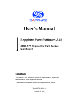
Motherboard Layout
Figure 1 shows the motherboard and Figure 2 shows the back panel connectors.
Figure 1. Board Layout
1. Reset Switch-SW2
2. Power Button-SW3
3. 24-pin ATX Power Connector-PW1
4. CPU Fan Connector-CPUFAN1
5. Front Panel Header-FP1
6. Speaker Header-SPK1
7. PCI Express x16 Slot-PCIE1
8. CPU Socket
9. Front Panel Audio Header-FP_S1
10. SPDIF-Out Header-SPDIF
11. 8-pin ATX_12V power connector-PW2
12. Backpanel Connectors
13. USB 3.0 Header-FP_USB3_1
14. COM Header-CN4 (Optional)
15. Clear CMOS Jumper-JP1
16. USB 2.0 Headers (FP_U1~FP_U2)
17. SATAIII Connectors (SATA1~2)
18.
Chipset
19. SATAII Connectors (SATA3~4)
20. SYS Fan Connector-SYSFAN1
21. Mini PCI Express Slot (mSATA)-MINI_PCIE2
22. ME Update Jumper-JP5 (Optional)
23. Mini PCI Express Slot-M_PCIE1
24. DDRIII DIMM Sockets-DDRIII1~2
Figure 1

7
Rear panel
1. USB 2.0 Ports
2. Clear CMOS Button
3. USB 3.0 Ports
1
2
3
4
7
9
8
5 6 5
10
Figure 2. Backpanel connectors
5. HDMI Ports
6. Mini Display Port
7. Optical SPDIF Output
4. LAN port LED indicators
Speed LED Activity LED
8. Port 2-Channel 4-Channel 6-Channel 8-Channel
Blue Line-In Line-In Line-In Side Speaker Out
Green Line-Out Front Speaker Out Front Speaker Out Front Speaker Out
Pink Mic In Mic In Mic In Mic In
Black -- -- Center/Subwoofer Center/Subwoofer
Orange -- Rear Speaker Out Rear Speaker Out Rear Speaker Out
9. PS2 Keyboard/Mouse Port
(Refer to page 21 to set PS2 Keyboard/Mouse Swap)
Activity LED
Status Descritption
Off No link
Orange Linked
Blinking Data activity
Speed LED
Status Description
Off Speed: 10 Mbps
Green Speed: 100 Mbps
Orange Speed: 1000 Mbps

8
Intel Z77-ITX series Motherboard
10. WiFi/BT antenna connectors (Optional)
This motherboard can support two antennas for WiFi/BT combo. Refer to the following to
install the WiFi/BT antennas.
Step 1. Remove the red caps from the WiFi/BT antenna connectors.
Step 2. Install the antennas to the WiFi/BT antenna connectors, and make sure the screws
are rotated in clockwise direction.
Note:
1. Users please note that the appearance of your WiFi/BT antennas may not be exactly
the same as those shown in this manual.
2. Users need to install WiFi/BT antennas to the motherboard for better signal
reception.
3. Users can bend or rotate the WiFi/BT antennas to the best receiving direction
according to the picture below.
120
240
121
120
240
121
1.5V
1.5V
115XLM
REMOVE
+

9
Hardware Installation
This section will guide you through the installation of the motherboard. The topics covered in this
section are:
q Preparing the motherboard
v Installing the CPU
v Installing the CPU fan
v Installing Memory DIMMs
q Installing the motherboard
v Installing the I/O Shield
v Securing the Motherboard into the Chassis
v Installing an mSATA SSD module (optional)
q Connecting cables and setting switches
Safety Instructions
To reduce the risk of re, electric shock, and injury, always follow basic safety precautions.
Remember to remove power from your computer by disconnecting the AC main source before
removing or installing any equipment from/to the computer chassis.
Hardware Installation

10
Intel Z77-ITX series Motherboard
Preparing the Motherboard
The motherboard shipped in the box does not contain a CPU and memory DIMM. You need to
purchase them to complete this installation.
Installing the CPU
Be very careful when handling the CPU. Make sure not to bend or break any pins on the back.
Hold the processor only by the edges and do not touch the bottom of the processor.
The following illustration shows CPU installation components
1. Unhook the socket lever by pushing down
and away from the socket.
2. Lift the socket lever and the load plate to
fully open position.
3. Use your thumb and forenger to lift the cap
up vertically.
● Be careful not to touch the socket contacts.
4. Hold the processor with your thumb and
forenger. Insert the processor into the socket
vertically.
● Align the CPU pin 1 mark with the pin 1
corner of the CPU socket.
5. Make sure the CPU is fully seated, and then
replace the load plate.
● Be sure that the front end of the load
plate is under the shoulder screw.
6. Secure the load lever to its locked location.

11
Installing the CPU Fan
There are many different fan types that can be used with this motherboard. Follow the instruction
that came with your fan assembly. Be sure that the fan orientation is correct for your chassis type
and your fan assembly.
Installing Memory Modules
Your new motherboard has two 1.5V 240-pin slots for DDR3 memory. These slots support 1
GB/2 GB/4 GB/8 GB DDR3 devices. There must be at least one memory bank populated to
ensure normal operation. Refer to the following recommendations to install memory modules.
Note that a memory module has a notch, so it can only t in one direction. Refer to the following
procedure to install memory modules into the slots on the motherboard.
1. Unlock a DIMM slot by pressing the module clips outward.
2. Align the memory module to the DIMM slot, and insert the module vertically into the DIMM
slot. The plastic clips at both sides of the DIMM slot automatically lock the DIMM into the
connector.
120
240
121
120
240
121
1.5V
1.5V
115XLM
REMOVE
+
DDRIII1
DDRIII2
Hardware Installation

12
Intel Z77-ITX series Motherboard
Installing the Motherboard
The sequence of installing the motherboard into the chassis depends on the chassis you are
using and if you are replacing an existing motherboard or working with an empty chassis. Deter-
mine if it would be easier to make all the connections prior to this step or to secure the mother-
board and then make all the connections. It is normally easier to secure the motherboard rst.
Use the following procedure to install the I/O shield and secure the motherboard into the chassis.
Note: Be sure that the CPU fan assembly has enough clearance for the chassis covers
to lock into place and for the expansion cards. Also make sure the CPU Fan assem
-bly is aligned with the vents on the covers.
Installing the I/O Shield
The motherboard kit comes with an I/O shield that is used to block radio frequency transmis-
sions, protects internal components from dust and foreign objects, and promotes correct airow
within the chassis.
Before installing the motherboard, install the I/O shield from the inside of the chassis. Press the
I/O shield into place and make sure it ts securely. If the I/O shield does not t into the chassis,
you would need to obtain the proper size from the chassis supplier.
Securing the Motherboard into the Chassis
Most computer chassis have a base with mounting studs or spacers to allow the motherboard
to be secured to the chassis and help to prevent short circuits. If there are studs that do not
align with a mounting hole on the motherboard, it is recommended that you remove that stud
to prevent the possibility of a short circuit. In most cases, it is recommended to secure the
motherboard with spacers.
1. Carefully place the motherboard onto the studs/spacers located inside the chassis.
2. Align the mounting holes with the studs/spacers.
3. Align the connectors to the I/O shield.
4. Ensure that the fan assembly is aligned with the chassis vents according to the fan assembly
instruction.
5. Secure the motherboard with screws.

13
Hardware Installation
Connecting Cables and Setting Switches
This section takes you through all the connectors and switch settings necessary on the mother-
board. This will include:
q Power Connectors
v 24-pin ATX Power Connector-PW1
v 8-pin ATX_12V Power Connector-PW2
q Internal Headers/Connectors
v SPDIF-Out Header-SPDIF
v COM Header-CN4 (Optional)
v Front Panel Header-FP1
v USB Headers (FP_U1/2/FP_USB3-1)
v Front Panel Audio Header-FP_S1
v Speaker Header-SPK1
q Serial-ATA (SATA) Connectors (SATA1~4)
q Fan Connectors
q Expansion Slots
q Jumper Settings
See Figure 1 to locate the connectors and jumpers referenced in the following procedure.

14
Intel Z77-ITX series Motherboard
24-pin ATX Power Connector-PW1
PW1 is the main power supply connector. Make sure that the power supply cable and pins are
properly aligned with the connector on the motherboard. Firmly plug the power supply cable into
the connector and make sure it is secure.
PW1-Pin Denition
Pin Signal Pin Signal
1 +3.3V 13 +3.3V
2 +3.3V 14 -12V
3 GND 15 GND
4 +5V 16 PS_ON
5 GND 17 GND
6 +5V 18 GND
7 GND 19 GND
8 PWROK 20 -5V
9 +5V_AUX 21 +5V
10 +12V 22 +5V
11 +12V 23 +5V
12 +3.3V 24 GND
8-pin ATX_12V Power Connector-PW2
PW2, the 8-pin ATX 12V power connection, is used to provide power to the CPU. Align the pins
to the connector and press rmly until seated.
PW2-Pin Denition
Pin Signal Pin Signal
1 GND 5 +12V
2 GND 6 +12V
3 GND 7 +12V
4 GND 8 +12V
120
240
121
120
240
121
1.5V
1.5V
115XLM
REMOVE
+
1
PW2
PW1
1
12
13
24

15
Hardware Installation
SPDIF-Out Header-SPDIF
This header provides a SPDIF (Sony/Philips Digital Interface) output to digital multimedia
device through coaxial connector.
SPDIF - Pin Denition
Pin Signal
1 GND
2 SPDIF-out
3 VCC
q PWRLED
Attach the front panel power LED cable to these two pins of the connector. The Power LED
indicates the system’s status.
q PWR SW
Attach the power button cable from the case to these two pins. Pressing the power button
on the front panel turns the system on and off rather than using the power supply button.
q HDD LED
Attach the hard disk drive indicator LED cable to these two pins. The HDD indicator LED
indicates the activity status of the hard disks.
q RST SW
Attach the Reset switch cable from the front panel of the case to these two pins. The system
restarts when the RESET switch is pressed.
Note: Some chassis do not have all four cables. Be sure to match the name on the
connectors to the corresponding pins.
Front Panel Header-FP1
The front panel header on this motherboard is
one connector used to connect the following four
cables :
SPDIF
1
120
240
121
120
240
121
1.5V
1.5V
115XLM
REMOVE
+
FP1
CN4
1
COM Header-CN4 (Optional)
CN4 - Pin Denition
Pin Signal Pin Signal
1 DCD 2 RXD
3 TXD 4 DTR
5 GND 6 DSR
7 RTS 8 CTS
9 RI 10 NC
FP1-Pin Denition
Pin Signal Pin Signal
1 HDD_LED+ 2 PW_LED+
3 HDD_LED- 4 PW_LED-
5 GND 6 PWR_SW
7 RESET 8 GND
9 NC 10 KEY
1

16
Intel Z77-ITX series Motherboard
USB Headers-FP_U1/2/FP_USB3_1
This motherboard contains four USB 2.0 and two USB 3.0 ports that are exposed on the rear
panel of the chassis. The motherboard also contains two 10-pin internal USB 2.0 headers and
one 20-pin USB 3.0 connector onboard.
Front Panel Audio Header-FP_S1
The audio connector supports HD audio standard
and provides two kinds of audio output choices: the
Front Audio, the Rear Audio. The front Audio supports
retasking function.
Note:
In order to utilize the front audio
header, your chassis must have front
audio connector. Also please make
sure the pin assignment on the cable
is the same as the pin assignment
on the mainboard header. To nd
out if the chassis you are buying
supports a front audio connector,
please contact your dealer.
FP_U1~FP_U2-Pin Denition
PIN Assignment PIN Assignment
1 VCC 2 VCC
3 USBP0- 4 USBP1-
5 USBP0+ 6 USBP1+
7 GND 8 GND
9 KEY 10 NC
FP_S1-Pin Denition
PIN Assignment PIN Assignment
1 MIC2(L) 2 GND
3 MIC(R) 4 -ACZ-DET
5 Front Audio(R) 6 Reserved
7 FAVDIO-JD 8 Key(No pin)
9 Front Audio(L) 10 Reserved
120
240
121
120
240
121
1.5V
1.5V
115XLM
REMOVE
+
1
FP_S1
1
FP_U1
1
FP_U2
FP_USB3_1
1
FP_USB3_1-Pin Denition
Pin Signal Pin Signal
1 NC 2 BD+
3 AD+ 4 BD-
5 AD- 6 GND2
7 GND1 8 BSSTX+
9 ASSTX+ 10 BSSTX-
11 ASSTX- 12 GND3
13 GND 14 BSSRX+
15 ASSRX+ 16 BSSRX-
17 ASSRX- 18 BVBUS
19 AVBUS 20 KEY
Note: Secure the bracket to
either the front or rear panel
of your chassis (not all chas-
sis are equipped with the front
panel option).

17
Hardware Installation
Speaker Header-SPK1
Serial-ATA (SATA) Connectors (SATA1~4)
The Serial ATA connector is used to connect the Serial ATA
device to the motherboard. These connectors support the thin
Serial ATA cables for primary storage devices. The motherboard
incorporates two SATA II ports (SATA3/4) with maximum transfer
rate up to 3.0 Gb/s each and two SATA III ports (SATA1/2) with
maximum tranansfer rate up to 6.0 Gb/s each.
SPK1-Pin Denition
PIN Assignment
1 VCC
2 NC
3 NC
4 SPK-
SATA-Pin Denition
Pin Signal
1 GND
2 TXP
3 TXN
4 GND
5 RXN
6 RXP
7 GND
Fan Connectors
There are two fan connectors on the motherboard, including
system fan connector-SYSFAN1 and CPU fan connector-CPU-
FAN1.
SPK1
1
120
240
121
120
240
121
1.5V
1.5V
115XLM
REMOVE
+
SATA1
CPUFAN1
GND
+12V
Sense
Control
SATA2
SATA3
SATA4
SYS_FAN1
GND
+12V
Sense
Control

18
Intel Z77-ITX series Motherboard
Mini PCI Express Slots-M_PCIE1/MINI_PCIE2
There are two Mini PCI Express slots. M_PCIE1 supports one half-sized WiFi card. MINI_PCIE2
supports one mSATA SSD.
PCIe x16 Slot-PCIE1
There is one PCIe x16 slot reserved for graphics card. It is fully compliant with PCIE 3.0
specication.
Jumper Settings
This section explains how to congure the motherboard’s hardware. Before using your
computer, make sure all jumpers and DRAM modules are set correctly. Refer to this section
whenever in doubt.
CMOS Clear Jumper-JP1
Close Open * = Default setting.
If you want to clear the system conguration, use the JP1 (Clear CMOS Jumper) to clear data.
Notice:
1. Be sure to save the CMOS setting when exit the CMOS.
2. If the CPU is frequency multiplier locked, no CPU speed change will be seen even if the
frequency multiplier setting in CMOS setup is changed.
JP1 Selection
1-2* Normal*
2-3 CMOS Clear
1
1
Expansion Slots
The motherboard contains three expansion slots, two Mini PCIe slots and one PCIe x16 slot.
120
240
121
120
240
121
1.5V
1.5V
115XLM
REMOVE
+
M_PCIE1
PCIE1
MINI_PCIE2
ME Update Jumper-JP5 (optional)
JP5 Selection
1-2* Normal*
2-3 Intel
®
Management Engine
(ME) update
1
1

19
Conguring the BIOS
Conguring the BIOS
This section discusses how to change the system settings through the BIOS Setup
menus. Detailed descriptions of the BIOS parameters are also provided.
Enter BIOS Setup
The BIOS is the communication bridge between hardware and software. Correctly
setting the BIOS parameters is critical to maintain optimal system performance.
Refer to the following procedure to verify/change BIOS settings.
1. Power on the computer.
2. Press the Del key when the following message briey displays at the bottom of
the screen during the Power On Self Test (POST).
Pressing Del takes you to the BIOS Setup Utility.
Note: 1. We reserve the right to update the BIOS version presented in the manual. The
BIOS pictures shown in this section are for reference only.
2. It is strongly recommended that you do not change the default BIOS settings.
Changing some settings could damage your system.
Main Menu
Note: Users please note that the data in gray is non-changeable, and the others are for selection.
This menu gives you an overview of the general system specications. The BIOS
automatically detects the items in this menu.
q BIOS Information
Displays the auto-detected BIOS information.
/