Page is loading ...

The SM5-KIT includes four sturdy 5-hole Aluminum mounting brackets (Fig. 1) with stainless steel hardware
required to securely fasten a solar panel to the roof of your Recreational Vehicle (RV) or any other at surface.
1/4” holes
3/8” holes
Fig.1. 5-hole mounting bracket
List of Parts (Included in the kit)
Part Description Quantity Illustration
1. 5-hole aluminum mounting bracket 4 Fig. 1
2. Stainless steel serrated ange bolt ¼”-20 x ¾" 4 Fig. 7
3. Stainless steel nylon insert locknut, ¼” 4 Fig. 7
4. Stainless steel at washer, ¼”-20 8 Fig. 7
5. Well Nut-Nut thread: ¼”-20, length: 1”, shank dia.: ½” 4 Fi g. 2
6. Stainless steel serrated ange bolt, ¼”-20 x 1¼” 4 Fig. 8
Owner's
Manual
Please read this
manual before
installing your kit
5-hole
Solar Panel
Mounting
Bracket Kit
SM5-KIT
Required Tools (Not included in the kit)
7/16” wrench 3/8” wrench
Hand Drill ½” drill bit
Pliers Punch or Awl
1
INTRODUCTION
Pre-installation
With the incidence of sunlight on all photovoltaic modules, a voltage appears at the output terminals of the
photovoltaic module turning it into a live power source. To avoid a shock hazard make sure the solar module
is covered with an opaque (dark) material such as paper / cloth.
Stainless Steel can be subject to a process called “thread galling” in which bolts can twist off and/or the bolt
threads seize to the nut’s thread. Apply anti-galling lubricant available at most hardware or auto-parts stores
to all the stainless steel fasteners before installation. If anti-galling lubricant is not available, any standard
lubricant will minimize the occurrence of “thread galling”.
11013-SM5-KIT-1112
MAN-10004
2 YEAR LIMITED WARRANTY
The SM5-KIT manufactured by Samlex America, Inc. (the “Warrantor“) is warranted to be
free from defects in workmanship and materials under normal use and service. The war-
ranty period is 2 years for the United States and Canada, and is in effect from the date of
purchase by the user (the “Purchaser“).
Warranty outside of the United States and Canada is limited to 6 months. For a warranty
claim, the Purchaser should contact the place of purchase to obtain a Return Authoriza-
tion Number.
The defective part or unit should be returned at the Purchaser’s expense to the authorized
location. A written statement describing the nature of the defect, the date of purchase,
the place of purchase, and the Purchaser’s name, address and telephone number should
also be included.
If upon the Warrantor’s examination, the defect proves to be the result of defective mate-
rial or workmanship, the equipment will be repaired or replaced at the Warrantor’s option
without charge, and returned to the Purchaser at the Warrantor’s expense. (Contiguous
US and Canada only)
No refund of the purchase price will be granted to the Purchaser, unless the Warrantor is
unable to remedy the defect after having a reasonable number of opportunities to do so.
Warranty service shall be performed only by the Warrantor. Any attempt to remedy the
defect by anyone other than the Warrantor shall render this warranty void. There shall
be no warranty for defects or damages caused by faulty installation or hook-up, abuse or
misuse of the equipment including exposure to excessive heat, salt or fresh water spray, or
water immersion.
No other express warranty is hereby given and there are no warranties which extend
beyond those described herein. This warranty is expressly in lieu of any other expressed
or implied warranties, including any implied warranty of merchantability, tness for the
ordinary purposes for which such goods are used, or tness for a particular purpose, or
any other obligations on the part of the Warrantor or its employees and representatives.
There shall be no responsibility or liability whatsoever on the part of the Warrantor or
its employees and representatives for injury to any persons, or damage to person or
persons, or damage to property, or loss of income or prot, or any other consequential or
resulting damage which may be claimed to have been incurred through the use or sale of
the equipment, including any possible failure of malfunction of the equipment, or part
thereof. The Warrantor assumes no liability for incidental or consequential damages of
any kind.
Samlex America Inc. (the “Warrantor”)
www.samlexamerica.com
4
103 - 4268 Lozells Ave.
Burnaby, BC
Canada V5A 0C6
T: 604 525 3836
F: 604 525 5221
TF: 1 800 561 5885
e-mail: samlex@samlexsolar.com
website: www.samlexsolar.com

32
solar module
1/4” -20x3/4” ange bolt
1/4” at washer
1/4” locknut
mounting bracket
RV roof
Fig. 7. Attaching solar panel to 5-hole mounting bracket
4. Position the panel with the attached mounting brackets at the desired location on the RV roof and
mark the position of the mounting holes by tracing the hole in the mounting bracket. Please ensure
that the mounting surface on the RV roof is strong enough to support the mounting hardware, solar
panel and wind loads.
5. The centre and end holes on the mounting brackets (Fig. 1) are sized to accept the ¼” hardware
supplied with the kit. If the use of larger sized hardware is desired, holes 2 and 4 can be used.
6. To install the Well-Nuts, for anchoring the brackets to the RV roof or a at surface, drill holes 1¼”
deep at the marked positions using a ½” size drill bit. Make sure that drilling does not interfere with
pre-existing wiring installations.
7. Apply silicone or any appropriate sealant recommended by your RV dealer generously to the drilled
holes for water-proo ng.
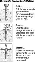
8. Insert the ¼” Well-Nut into the drilled holes so that only the ange section remains above the roof
surface (Fig. 3).
9. Fasten the mounting brackets to the roof surface by inserting the ¼ x 1¼” serrated ange bolt into
the Well-Nut. Tighten using a 3/8” wrench to a recommended torque of 15 lbs. When the serrated
ange bolt is screwed into the Well-Nut, the material surrounding the well nut bulges slightly
securing the structure to the RV roof (Fig. 5, 8).
10. Ensure that all fasteners are tightened to the recommended tightening torque.
11. Make sure all bolts and mounting brackets are covered by good amounts of suitable RV sealant
recommended by your local RV dealer.
Rubber bushing material expands
when bolt is tightened to securely
anchor hardware
solar
module
¼”-20 x 1¼” ange bolt
¼” at washer
Well-Nut
mounting bracket
RV roof material
up to approx. 3/8”
thickness
Fig. 8. Attaching 5-hole mounting bracket to RV roof
Well Nut for anchoring mounting bracket to the RV Roof or at surface
A Well-Nut is a bushing of tough neoprene rubber with a ange at the top end and a captive brass nut
mounted within the bore at the bottom end (Fig. 2). This is used to anchor the mounting bracket (Fig.1)
on to the roof of the RV or to other at surface. Typical installation is shown in Figs 3 to 6. Tightening
a conventional machine bolt or screw engages the captive nut thereby causing the bushing to expand
outwards. This fastens securely to thinner RV roofs by bulging up and against the bottom surface of the roof
(Fig. 5). If used in a blind hole in a solid surface material, the rubber will expand outwards to create a secure
fastening (Fig. 6). The neoprene and brass resist most environmental conditions. Additionally, the Well-Nut
seals the drilled hole effectively against air and liquid leakage.
ange
1/2” diameter
1/4” captive brass nut
Fig. 2. Construction of a Well Nut
Typical Installation of a Well-Nut
RV Roong
Material
Well Nut
Fig. 3. Well-Nut is inserted
into a pre-drilled hole
with its ange against the
outer surface. There is no
need for access to the
inner side.
1/4”-20 x 1
1/4
”
Serrated
Flange Bolt
Mounting
Bracket
Captive
Brass Nut
Fig. 4. The 5-hole mounting
bracket is placed against
the ange of the Well-Nut
and is secured by the 1/4"-
20 x 1
1/4
" serrated ange
bolt engaging the captive
brass nut.
Fig. 5. As the bolt is tight-
ened, the neoprene body of
the Well-Nut is compressed
and expanded, forcing it
tightly into the bolt's threads
and against the inner surface
of the thin RV roof material.
Fig. 6. Installed in a
blind hole in a solid ma-
terial, the body of the
Well-Nut expands tightly
against the walls of the
hole, effecting a secure,
dependable fastening.
INSTALLATION PROCEDURE
1. Determine the position of the solar panel on the RV roof or at surface. While positioning panels, avoid
shading of the solar panel by neighbouring obstacles such as vents, air-conditioners, TV antennas etc. As
far as possible, position the panels to minimize wiring distance between the solar panel and the charge
controller. Place the panel at least 8-10 inches away from the RV roof edges and leave suf cient space to
walk around the panel and access the mounting hardware.
2. Make sure the thickness of the roof at the installation location is at least ½” thick and the material
is strong enough to provide mechanical support to the solar panel and mounting hardware against
possible wind loading. Place the panel length-wise to reduce the effects of wind loading on the RV.
3. Fix the mounting brackets to the frame of the previously positioned solar panel using the slotted
opening and the ¼”-20 x ¾" Flange Bolt, Nylon Locknut and at washer (Fig. 7). Using a 7/16” wrench,
tighten the nuts to secure the mounting brackets to the PV panel. Recommended tightening torque is
15 lbs.
/


