Page is loading ...

Quick Installation Guide
00825-0100-4830, Rev AA
January 2004
Rosemount 415 Fire Pump
www.rosemount.com
¢00825-0100-4830e¤
Rosemount 415 Fire Pump
Step 1: Location and Orientation
Step 2: Drill Holes into Pipe
Step 3: Weld Mounting Hardware
Step 4: Insert the Annubar
4830 Rev AA.fm Page 1 Wednesday, January 14, 2004 3:29 PM

Quick Installation Guide
00825-0100-4830, Rev AA
January 2004
Rosemount 415 Fire Pump
© 2004 Rosemount Inc. All rights reserved. All marks are the property of their owners.
Rosemount Inc.
8200 Market Boulevard
Chanhassen, MN USA 55317
T (US) (800) 999-9307
T (Intnl) (952) 906-8888
F (952) 949-7001
Emerson Process Management
GmbH & Co. OHG
Argelsrieder Feld 3
82234 Wessling
Germany
T 49 (8153) 9390
F49 (8153) 939172
Emerson Process Management
Asia Pacific Private Limited
1 Pandan Crescent
Singapore 128461
T (65) 6777 8211
F (65) 6777 0947/65 6777 0743
Beijing Rosemount Far East
Instrument Co., Limited
No. 6 North Street,
Hepingli, Dong Cheng District
Beijing 100013, China
T (86) (10) 6428 2233
F (86) (10) 6422 8586
IMPORTANT NOTICE
This installation guide provides basic guidelines for Rosemount Eagle Eye
Fire Pump. It does not provide instructions for configuration, diagnostics,
maintenance, service, troubleshooting, Explosion-proof, Flame-Proof, or
instrinsically safe (I.S.) installations. Refer to the Rosemount Eagle Eye
Series Product Data Sheet (document number 00813-0100-4830) or the
Eagle Eye QIG (document number 00825-0100-4833) for more information.
These documents are also available electronically on www.rosemount.com.
WARNING
Process leaks may cause harm or result in death. To avoid process leaks,
only use gaskets designed to seal with the corresponding flange and o-rings
to seal process connections. Flowing medium may cause the 485 Annubar
assembly to become hot and could result in burns.
4830 Rev AA.fm Page 2 Wednesday, January 14, 2004 3:29 PM

Quick Installation Guide
00825-0100-4830, Rev AA
January 2004
Rosemount 415 Fire Pump
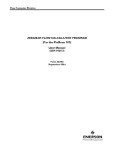
EXPLODED VIEW
need
Eagle Eye Indicator
1
/4-in. O.D. Tube
Mounting U-Bolt
Washer
Nut
Compression Plate
Stud
Packing Rings (3)
Annubar Sensor
Pak-Lok Body
1
/8-in. NPT x
1
/4-in. Reducer
1
/8-in. Ball Valve
1
/8-in. NPT x
1
/4-in.
SAE Flare Adapter
31-490000-901A
4830 Rev AA.fm Page 3 Wednesday, January 14, 2004 3:29 PM

Quick Installation Guide
00825-0100-4830, Rev AA
January 2004
Rosemount 415 Fire Pump
STEP 1: LOCATION AND ORIENTATION
Correct orientation and straight run requirements must be met for
accurate and repeatable flow measurements. Refer to Table 1 for
minimum pipe diameter distances from upstream disturbances.
Table 1. Straight Run Requirements
Upstream Dimensions
Downstream
Dimensions
Without Vanes With Vanes
In
Plane A
Out of
Plane A
A’ C C’
1
8
—
10
—
—
8
—
4
—
4
4
4
2
11
—
16
—
—
8
—
4
—
4
4
4
3
23
—
28
—
—
8
—
4
—
4
4
4
4830 Rev AA.fm Page 4 Wednesday, January 14, 2004 3:29 PM

Quick Installation Guide
00825-0100-4830, Rev AA
January 2004
Rosemount 415 Fire Pump
STEP 1 CONTINUED...
Upstream Dimensions
Downstream
Dimensions
Without Vanes With Vanes
In
Plane A
Out of
Plane A
A’ C C’
4
12
—
12
—
—
8
—
4
—
4
4
4
5
18
—
18
—
—
8
—
4
—
4
4
4
6
30
—
30
—
—
8
—
4
—
4
4
4
4830 Rev AA.fm Page 5 Wednesday, January 14, 2004 3:29 PM

Quick Installation Guide
00825-0100-4830, Rev AA
January 2004
Rosemount 415 Fire Pump
STEP 1 CONTINUED...
NOTE
• “In Plane A” means the bar is in the same plane as the elbow.
“Out of Plane A” means the bar is perpendicular to the plane of
the elbow.
• If proper lengths of straight run are not available, position the
mounting such that 80% of the run is upstream and 20% is
downstream.
• Use straightening vanes to reduce the required straight run
length.
• Row 6 in Table 1 applies to gate, globe, plug, and other
throttling valves that are partially opened, as well as control
valves.
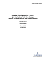
Misalignment
The 415 Fire Pump Annubar installation allows for a maximum
misalignment of 3°.
Figure 1. Misalignment
3°
3°3°
31-490000-902A
4830 Rev AA.fm Page 6 Wednesday, January 14, 2004 3:29 PM

Quick Installation Guide
00825-0100-4830, Rev AA
January 2004
Rosemount 415 Fire Pump
STEP 1 CONTINUED...
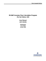
Orientation
For proper venting and draining, the sensor should be located in the
bottom half of the pipe.
Figure 2. Orientation
STEP 2: DRILL HOLES INTO PIPE
1. Determine the sensor size based on the probe width (see Table 2).
2. Depressurize and drain the pipe.
3. Select the location to drill the hole.
4. Determine the diameter of the hole to be drilled according to the
specifications in Table 2. Drill the mounting hole into the pipe with a
hole saw or drill. DO NOT TORCH CUT THE HOLE.
Table 2. Sensor Size / Hole Diameter Chart
Sensor
Width
Sensor
Size
Hole Diameter
0.590-in.
(14.99 mm)
1
3
/4-in.
(20 mm)
+ 1/32-in (1 mm)
– 0.00
1.060-in.
(26.92 mm)
2
1
5
/16-in.
(35 mm)
+
1
/16-in. (1 mm)
– 0.00
31-490000-903A
60 °60 °
60 ° Recommended Zone
31-490000-904A
4830 Rev AA.fm Page 7 Wednesday, January 14, 2004 3:29 PM

Quick Installation Guide
00825-0100-4830, Rev AA
January 2004
Rosemount 415 Fire Pump
STEP 3: WELD MOUNTING HARDWARE
1. Center the 415 Fire Pump Pak-Lok body over the mounting hole,
gap
1
/16-in. (1.5 mm), and place four
1
/4-in. (6-mm) tack welds at
90° increments.
2. Check alignment of the 415 Fire Pump Pak-Lok body both parallel
and perpendicular to the axis of flow (see Figure 3). If alignment of
mounting is within tolerances, finish weld per local codes. If
alignment is outside of specified tolerance make adjustments prior
to finish weld.
3. To avoid serious burns, allow the mounting hardware to cool before
continuing.
Figure 3. Alignment
(1) LMH values are as follows:
Sensor Size 1: 2.89-in. (73 mm)
Sensor Size 2: 3.92-in. (100 mm)
LMH
(1)
Tack
Welds
31-490000-905A
4830 Rev AA.fm Page 8 Wednesday, January 14, 2004 3:29 PM

Quick Installation Guide
00825-0100-4830, Rev AA
January 2004
Rosemount 415 Fire Pump
STEP 4: INSERT THE ANNUBAR
1. Thread studs into the 415 Fire Pump Annubar assembly.
2. To ensure that the flowmeter contacts the opposite side wall, mark
the tip of the sensor with a marker.
3. Insert the flowmeter into the 415 Fire Pump Annubar body until the
sensor tip contacts the pipe wall, rotating the flowmeter back and
forth.
4. Remove the flowmeter.
5. Verify that the sensor tip made contact with the pipe wall by
ensuring that some of the marker has been rubbed off. If the tip did
not touch the wall, verify pipe dimensions and the height of
mounting body from the outer diameter of the pipe and re-insert.
6. Align the flow arrow on the head with the direction of flow. Re-insert
the flow meter into the 415 Fire Pump Annubar body and install the
first packing ring on the sensor between the retaining ring and the
packing follower. Take care not to damage the split packing rings.
7. Push the packing ring into the 415 Fire Pump Annubar body and
against the weld retaining ring. Repeat this process for the two
remaining rings, alternating the location of the packing ring split by
180°.
Figure 4. Packing Ring Detail
Packing Rings (3)
Retaining Ring
Compression Plate
Follower
31-490000-906A
4830 Rev AA.fm Page 9 Wednesday, January 14, 2004 3:29 PM

Quick Installation Guide
00825-0100-4830, Rev AA
January 2004
Rosemount 415 Fire Pump
STEP 4 CONTINUED...
8. Tighten the nuts onto the studs:
a. Place the included split-ring lock washer between each of the
nuts and the compression plate. Give each nut one half turn in
succession until the split-ring lock washer is flat between the nut
and the compression plate. Torque is as follows.
b. Inspect the unit for leakage. If any exists, tighten the nuts in
one-quarter turn increments until there is no leakage.
NOTE
On sensor size (1), failure to use the split-ring Lock washers, improper
washer orientation, or over-tightening the nuts may result in flowmeter
damage.
Figure 5. Split-Ring Lock Washer Orientation
NOTE
The 415 Fire Pump Annubar sealing mechanisms generate significant
force at the point where the sensor contacts the opposite pipe wall.
Caution needs to be exercised on thin-walled piping (ANSI Sch 10 and
lower) to avoid damage to the pipe.
Sensor Size Torque Maximum Torque
1 40-in. / lb 60-in. / lb
2 100-in. / lb 360-in. / lb
Before
Tightening
After
Tightening
28-490000-943A
4830 Rev AA.fm Page 10 Wednesday, January 14, 2004 3:29 PM

Quick Installation Guide
00825-0100-4830, Rev AA
January 2004
Rosemount 415 Fire Pump
APPROVAL
Eagle Eye Fire Pump systems
Approved by Factory Mutual
The Eagle Eye Indicator
See the Eagle Eye Indicator Quick Installation Guide (document
number 00825-0100-4833).
4830 Rev AA.fm Page 11 Wednesday, January 14, 2004 3:29 PM

Quick Installation Guide
00825-0100-4830, Rev AA
January 2004
Rosemount 415 Fire Pump
4830 Rev AA.fm Page 12 Wednesday, January 14, 2004 3:29 PM
/