Extron DMP 128 Plus User manual

Category
Serial switch boxes
Type
User manual
DMP 128 Plus • Setup Guide
This guide provides basic instructions for an experienced technician to install the DMP 128 Plus ProDSP
Digital Matrix
Processor. For more information, specications, and the user guide, see the DMP 128 Plus product page on www.extron.com.
Disconnect Power and Mount the DMP 128 Plus
Disconnect power from the DMP 128 Plus and turn off all devices that will be connected to it. The DMP 128 Plus is housed in a
full rack width, 8.5 inch deep, 1U high metal enclosure that can be rack mounted or placed on a table with the provided rubber
feet. Select a suitable mounting location, then choose an appropriate mounting option. Mounting information can be found in the
DMP128 Plus User Guide on www.extron.com.
Make all external device connections before applying power.
Rear Panel Connections
100-240V 0.7A MAX
50 - 60 Hz
DMP 128 Plus C V AT
INPUTS
RxTx G
RS-232
+S+V -S G
GIN
1
O1 O2 GIN
2
O1 O2 GIN
3
O1 O2 GIN
4
O1 O2 GIN
5
O1 O2 GIN
6
O1 O2 GIN
7
O1 O2 GIN
8
O1 O2
56
78
11 12
1
2
3
4
9
10
1 2 3
4 5 6 7 8
I/O
OUTPUTS
DMP EXP
ACP
REMOTE
USB AUDIO
RESET
AT
1
(SEC)
2
3
4
(PRI)
LAN/VoIP
1
2
A B C D E F G
H
J K
I
Figure 1. DMP 128 Plus Rear Panel
A
AC Power — IEC power connector, 100—240 VAC, 50—60 Hz.
B
Digital I/O Ports — Connect up to eight 4-pole 3.5 mm captive screw connectors. These configurable digital input and
output ports are designed to connect to microphones with logic circuitry for mic mute and tally back functionality. Each port
provides a common ground.
C
Mic/Line Inputs — On inputs 1 through 8, use 3-pole 3.5 mm captive screw connectors to connect eight balanced or
unbalanced microphone or mono line level sources (see 3-pole Audio Input Wiring below). Inputs 1 through 8 provide
phantom power (all models) and AEC (C models only).
On inputs 9 through 12, use 6-pole 3.5mm captive screw connectors to connect up to four balanced or unbalanced
microphone or mono line level sources or two stereo sources (see 6-pole Audio Input Wiring below).
NOTES:
Balanced or unbalanced stereo sources can be connected to the
6-pole inputs.
When using the 5-pole CSR adapter, connect it so the far left plug
is inserted into the far left jack of the 6-pole input (see the example
to the right).
Figure 1
DMP 128 Plus C V AT
RS-
2
+S+V -S G
GN
7
O1 O2
GIN
8
O1 O2
5 6
7 8
11 12
1
2
3
4
9
10
7
8
OUTPUTS
DMP EXP
ACP
REMOTE
11
12
DO NOT
Connect Here
5-pole CSR
"
(5 mm) MAX. (typ)
3
16
3-pole Audio INPUT Wiring
Balanced Input
Sleev
e
Ring
Tip
Tip
Sleeve
Jumper
Unbalanced Input
Tip
Slee
ve
Ring
Tip
Slee
ve
Ring
Tip
Sleeve
Tip
Sleeve
6-pole Audio INPUT Wiring
Balanced Input Unbalanced Input
Jumper
Jumper
1
IMPORTANT:
Go to www.extron.com for the
complete user guide
, installation
instructions, and specifications.
D
Line Outputs — Use 6-pole 3.5 mm captive screw connectors to connect up to eight balanced or unbalanced mono line level
devices or four stereo devices (see Audio Output Wiring below).
Tip
Sleeve
Tip
Sleeve
Tip
Slee
ve
Ring
Tip
Slee
ve
Ring
6-pole Audio OUTPUT Wiring
Balanced Output Unbalanced Outpu
t
NO Ground Here
NO Ground Here
3-pole Audio OUTPUT Wiring
Unbalanced Output
Tip
Sleeve
NO Ground Here
Balanced Output
Tip
Sleev
e
Ring
E
EXP Port — Connect an EXP-enabled device to this RJ-45 port for a digital audio connection using Extron proprietary
protocol. Use the included one foot long shielded CAT 6 cable to connect two EXP-enabled devices to form a larger matrix
system. The expansion bus supports 16 bidirectional channels of audio (see the DMP 128 Plus User Guide for EXP bus
operation details).
F
ACP Panel Port — Use a 4-pole 3.5 mm captive screw connector to connect
an ACP control device for configuration via DSP Configurator (wiring shown to
the right).
G
RS-232 Port — Use a 3.5 mm 3-pole captive screw connector to connect the
host RS-232 cable for bidirectional RS-232 (±5V) serial control (wiring shown
to the right). The default baud rate is 38400.
H
LAN Ports — One RJ-45 port (non-V models) or two RJ-45 ports (V models)
are available for control network traffic (all models) and VoIP network traffic (V models only). On DMP 128 Plus V models, the
LAN/VoIP ports have multiple configuration options (refer to the DMP 128 Plus User Guide for configuration options). On
Vmodels, by default, both control and VoIP traffic are transported on LAN/VoIP 1.
Port Default IP Address Default Subnet Mask Default Gateway Default DHCP
LAN 1 192.168.254.254 255.255.255.0 0.0.0.0 OFF
LAN 2 (V models only) 192.168.1.254 255.255.255.0 0.0.0.0 OFF
I
AT Ports (AT models only) — Four RJ-45 ports form a Gigabit switch that interfaces with the AT bus. The AT expansion bus
uses Dante
protocol for digital audio networking and allows DMP 128 Plus AT models to connect with other Dante-enabled
devices to form a larger matrix (see the DMP 128 Plus User Guide for operation details).
NOTE: Dante Controller software is required to configure the AT expansion bus. Dante Controller is available at
www.extron.com (see the DMP 128 Plus User Guide for instructions on installation and operation).
J
USB Audio Port — Connect a Windows or Mac computer to this USB mini type B port to interface with the DMP 128 Plus as
a 4x4 USB audio device (see the DMP 128 Plus User Guide for USB audio interfacing capabilities).
K
Reset Button and LED — The reset button returns the DMP 128 Plus to different tiers of default states. When using the reset
function, the LED blinks to signify the different reset modes. When not using the reset function, the LED operates as a power
indicator and matches the front panel power LED (see the Reset Modes section of the DMP 128 Plus User Guide for more
information on the different reset modes).
When all connections have been made, power up the input and output devices, then apply power to the DMP 128 Plus.
Front Panel Features
DIGITAL MATRIX PROCESSOR
CONFIG
CLIP
EXP LAN USB
SIGNAL
CLIP
SIGNAL
1 2 3 4 5 6 7 8 1 2 3 4 5 6 7 89 10 11 12
ACTIVITY
INPUTS OUTPUTS
DMP 128 Plus
B C D EA
Figure 2. DMP 128 Plus Front Panel
A
Power LED — Blinks during boot up and lights steadily when the DMP 128 Plus is operational.
B
USB Config Port — One USB mini type B port is used for configuration. This port can also be used for firmware updates.
ATTENTION: For unbalanced audio outputs, connect the sleeves to the ground contact. DO NOT connect the sleeves
to the negative (-) contacts.
ATTENTION : Pour l’audio asymétrique, connectez les manchons au contact au sol. Ne PAS connecter les manchons
aux contacts négatifs (–).
G
Ground
+ Signal
-
Signal
+12 VDC
+V
-
S
+S
RS-232
Tx Rx G
TE
Transmit
Receive
Ground
Tx
Rx
G
Figure 2
2
C
Activity Indicator LEDs — These LEDs indicate activity or status on the rear panel EXP, LAN, and USB ports.
D
Input Indicator LEDs — Stacked green and red LEDs display input signal presence and input signal clipping.
E
Output Indicator LEDs — Stacked green and red LEDs display output signal presence and output signal clipping.
DSP Configurator Software Installation
There are no hardware controls for the DMP 128 Plus. All conguration and control is done using ExtronDSPCongurator
software. Install DSP Congurator on a PC running Microsoft
®
Windows
®
. For full computer requirements, see the DSP
Congurator product page on www.extron.com.
Download DSP Configurator from the Extron Website:
1. From the Extron home page (www.extron.com), click the Download tab to open the Download page.
2. Under Software, on the left side of the page, select DSP Configurator Software. The DSPConfiguratorSoftware
product page opens.
3. Click the Download button and follow the on-screen instructions.
NOTE: An Extron Insider account is required to download DSP Configurator.
DMP 128 Plus Configuration
When power is connected to the DMP 128 Plus and the rest of the audio system, audio output can easily be tailored to any
listening environment. When conguration is required, changes are made using DSP Congurator.
Configure the DMP 128 Plus:
1. Ensure the control computer is connected to
the LAN port (recommended), front panel USB
Cong port, or RS-232 port of the
DMP 128 Plus. Full conguration that includes
macros and ACP conguration requires a LAN
connection.
2. Start the DSP Congurator software. From the
splash screen drop-down menu, select the
DMP 128 Plus model corresponding to the
model connected to the control computer.
Click OK and the main workspace opens.
3. The software starts in Emulate mode.
a. To create a conguration le ofine and
upload (push) that conguration to the
DMP 128 Plus at a later time, remain in
Emulate mode and save the conguration
le.
b. To push a conguration to the DMP128Plus or pull the current conguration from the DMP 128 Plus, enter Live mode.
When in Live mode, changes made in DSP Congurator affect the connected DMP128Plus immediately. To enter Live
mode, click Live at the top of the DSP Congurator workspace, select Tools > Connect to Device, or press <F6>
on the keyboard.
NOTE: When Live mode is selected, a connection dialog box appears. Select the desired connection type and
follow the on-screen prompts (see the DMP 128 Plus User Guide for more information on connecting Live to a
device).
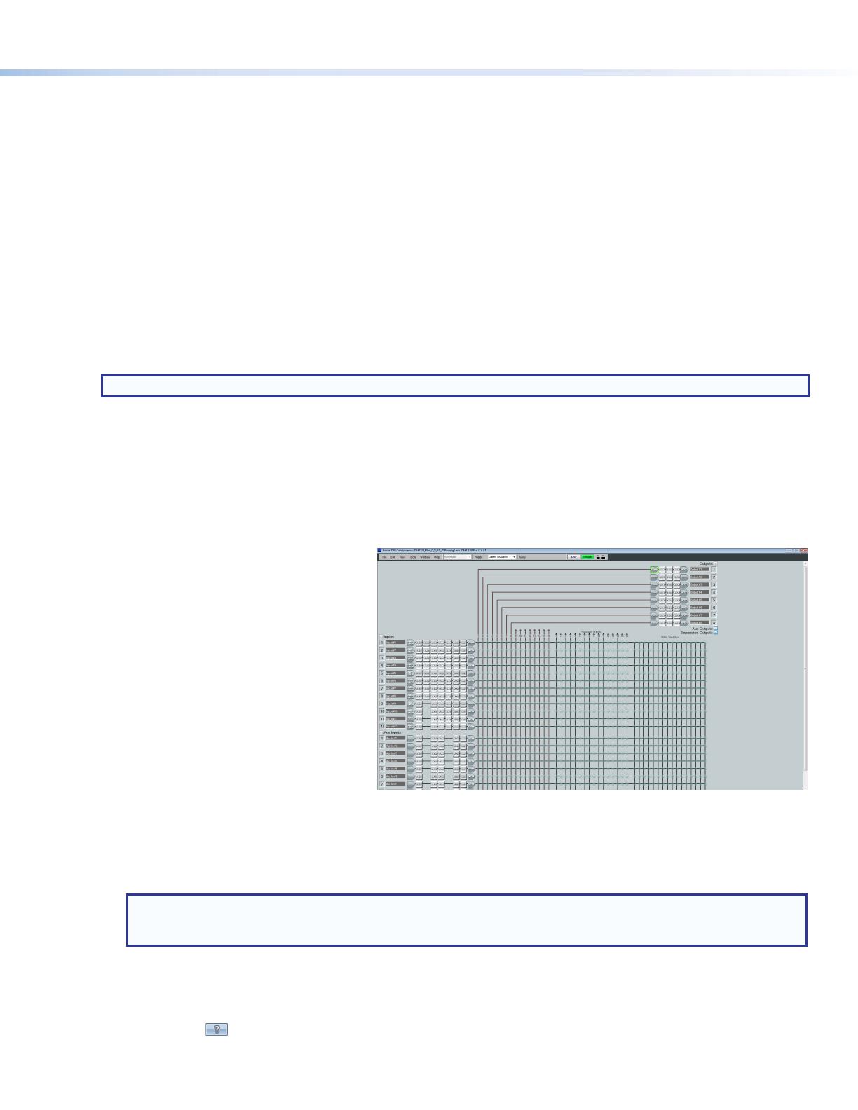
The main workspace provides access to mix matrices, gain blocks, and DSP processors for conguring the DMP 128 Plus. It also
provides a menu bar across the top with additional conguration tools. For more information about using DSP Congurator, see
the DSP Configurator Software section of the DMP 128 Plus User Guide or the DSP Configurator Help le that can be accessed
by selecting Help > Contents or pressing <F1> on the keyboard. Most dialog boxes within DSP Congurator contain a context
sensitive Help button ( ) in the top right corner. Click this button to open the help le topic for that specic dialog box.
3
Extron Headquarters
+800.633.9876 Inside USA/Canada Only
Extron USA - West Extron USA - East
+1.714.491.1500 +1.919.850.1000
+1.714.491.1517 FAX +1.919.850.1001 FAX
Extron Europe
+800.3987.6673
Inside Europe Only
+31.33.453.4040
+31.33.453.4050 FAX
Extron Asia
+65.6383.4400
+65.6383.4664 FAX
Extron Japan
+81.3.3511.7655
+81.3.3511.7656 FAX
Extron China
+86.21.3760.1568
+86.21.3760.1566 FAX
Extron Middle East
+971.4.299.1800
+971.4.299.1880 FAX
Extron Australia
+61.8.8113.6800
+61.8.8351.2511 FAX
Extron India
1800.3070.3777
(Inside India Only)
+91.80.3055.3777
+91.80.3055.3737 FAX
© 2017 Extron Electronics All rights reserved. All trademarks mentioned are the property of their respective owners. www.extron.com
Configure Dante Device Settings (AT Models Only):
Dante settings on DMP 128 Plus AT models can be congured from DSP Congurator. The Dante device can be named here,
which aids in device identication in the DanteController software when there are multiple Dante devices on the audio network.
ATTENTION: It is essential that a Dante device be named before audio subscriptions with other devices are
established. Existing subscriptions are removed when a device is renamed.
To configure Dante device settings:
1. Open DSP Congurator and connect Live to the DMP 128 Plus AT (see step 3b on the previous page).
2. Select Tools>Device Settings. The Device Settings dialog box opens.
3. From the tabs at the top of the Device Settings dialog box, select Dante
Device.
a. It may be necessary to use the right navigation arrow ( ) at the top right
corner of the Device Settings dialog box to navigate to the Dante
Device tab (see gure to the right).
4. In the Device name eld, give the DMP 128 Plus AT a meaningful name
(such as device model and location) so that it can be easily identied in
DanteController.
5. Dante device network settings can also be congured from this dialog box.
Use the radio buttons and text elds to choose DHCP (recommended) or
Static IP and enter a static IP address conguration.
NOTE: The device name and IP configuration in the Dante Device tab
only affect the Dante interface of the DMP128PlusAT. These settings
do not affect the device name recognized in DSP Configurator or the IP
address of the rear panel LAN port.
6. Select Enable Redundant Mode only if conguring the DMP 128 Plus AT
for use on redundant networks. A separate set of redundancy network settings opens for conguration (see Physical Dante
Network Setup in the DMP 128 Plus User Guide for more information on redundant conguration).
7. Click Apply.
8. Click OK to conrm changes and close the Device Settings dialog box.
For more information on conguring a DMP 128 Plus AT model in Dante Controller, refer to the Dante Controller section of the
DMP128PlusUser Guide (www.extron.com).
68-2826-50 Rev. C
07 17
  • Page 1 1
  • Page 2 2
  • Page 3 3
  • Page 4 4

Extron DMP 128 Plus User manual

Category
Serial switch boxes
Type
User manual

Ask a question and I''ll find the answer in the document

Finding information in a document is now easier with AI