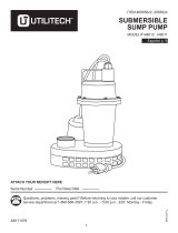
Everbilt HDS30 User guide

Type
User guide

Everbilt HDS30 is a sump pump designed to remove unwanted water from your sump basin and pump it away from your home. It features a powerful motor capable of pumping up to 3,000 gallons of water per hour, with a maximum head of 20 feet. The pump is made of durable cast iron and is equipped with an automatic float switch that turns the pump on when the water level rises and off when it drops. It also has a built-in check valve to prevent backflow of water into the sump basin.

Everbilt HDS30 is a sump pump designed to remove unwanted water from your sump basin and pump it away from your home. It features a powerful motor capable of pumping up to 3,000 gallons of water per hour, with a maximum head of 20 feet. The pump is made of durable cast iron and is equipped with an automatic float switch that turns the pump on when the water level rises and off when it drops. It also has a built-in check valve to prevent backflow of water into the sump basin.

THANK YOU
We appreciate t
he trust and confidence you have placed in Everbilt through the purchase of this sump pump. We strive to continually create quality
products designed to enhance your home. Visit us online to see our full line of products available for your home improvement needs. Thank you for
choosing Everbilt!
Item #1000 041 119
1000 041 120
Model #HDS30
HDS50
USE AND CARE GUIDE
SUMP PUMP
Questions, problems, missing parts? Before returning to the store,
call Everbilt Customer Service
8 a.m. - 6 p.m., EST, Monday-Friday
HOMEDEPOT.COM
1-844-883-1872
2
Table of Contents
Table of
Contents .......................................................... 2
Safet
y Information ......................................................... 2
Precautions ..............................................................................2
Electrical Safety
.......................................................................3
Warranty .........................................................................
3
Pre-Installation ..............................................................
4
Before FIrst Use
.......................................................................4
Intended Use
............................................................................4
Installation Requirements
........................................................4
Performance Chart
...................................................................5
Materials Required (Not Included)
...........................................5
Installation .....................................................................
6
Operation .......................................................................
7
Care and Cleaning
........................................................ 8
Additional Maintenance Guideli
nes ..........................................8
Troubleshooting ............................................................
9
Safety Information
PRECAUTIONS
1. Read instructions carefully before attempting
to install,
operate, or service this pump. Know the pump application,
limitations, and potential hazards. Protect yourself and
others by observing all safety information. Failure to comply
with instructions could result in personal injury and/or
property damage! Retain instructions for future reference.
2. Do not attempt to restrict the intake side of these pumps.
Restricting the intake may cause damage to the seal and
may starve the pump. If you require reduced flow rates, then
place a valve on the discharge side of the pump. If flexible
vinyl tubing is used, a clamp can be used on the tubing to
restrict the flow.
3. Do not let the unit run dry (without liquid). It is designed to
be cooled by pumping fluid. You may damage the seal and
the motor may fail if the pump is allowed to run dry.
4. If the unit is going to be idle for a period of time, follow the
cleaning instructions outlined in the Care and Cleaning
section. Do not let the unit freeze in the wintertime. This
may cause cracking or distortion that may destroy the unit.
DANGER: Keep pump equipment out of the reach of
children! Failure to follow the directions given could cause
serious risk
to individuals or objects.
WARNING: Warnings ind
icate to the operator that the
failur
e to follow an instruction may damage the pump
and/or the system.
WARNING: Before installing or servicing this pump, be
certain the power source is disconnected.
WARNING: Do not use to pump flammable or explosive
fluids such as gasoline, fuel oil, kerosene, etc. DO not use in
explosiv
e atmospheres or hazardous locations as classified
by NEC, ANSI/NFPAT. Use the pum
p with liquids compatible
with the pump component materials.
WARNING: Do not handle the pump with wet hands or
when standing on a wet or damp surface or in water.
WARNING: Do not pull the pump out of the water by the
power cord when the pump is operating or connected to a
power source.
WARNING: This pump is supplied with a grounding
conductor and/or grounding type attachment plug. To
reduc
e the risk of electrical shock, be certain that it is
connected to a p
roperly grounded grounding-type
receptacle.
WARNING: The National E
lectric Code requires a ground
fault circuit interrupter (GFCI) be i
nstalled in the branch
circuit supplying fountain equipment, pools, etc.
WARNING: In any instal
lation where property damage
and/
or personal injury might result from an inoperative or
leaking p
ump due to power outages, discharge line
blockage, or any other reason, a backup system(s) and/or
alarm sh
ould be used.
3
HOMEDEPOT.COM
Please contact 1-844-883-1872 for further assistance.
Safety Information (continued)
WARNING: Support the pump and piping when
assembling and when installed. Failure to do so may cause
the piping t
o break, pump to fail, motor bearing failures, etc.
WARNING: This pump’s motor housing is filled with a
diel
ectric oil for motor heat transfer and lifetime lubrication
of the bea
rings. This oil is non-toxic to aquatic life.
H
owever, suffocation can occur if oil is left on the water
surface. If oil escapes the motor housing it can be removed
from the surfac
e quickly by placing newspapers on the
water surfac
e to soak up the oil.
WARNING: The pump motor is equipped with an
automatic resetting thermal protector and may restart
unexpectedly. P
rotector tripping is an indication of the
motor ov
erloading as a result of excessively high or low
voltage, inadequate wiring, incorrect motor connections, or
a defective m
otor or pump.
ELECTRICAL SAFETY
WARNING: Chec
k the pump label for proper voltage
requi
red. Do not connect to voltage other than that shown.
WARNING: If pump is suppli
ed with a 3-prong electrical
plug, the thir
d prong is to ground the pump to prevent
possibl
e electrical shock hazard. DO NOT REMOVE the third
prong from the plug. A separate branch circuit is
rec
ommended. Do not use an extension cord. Do not cut the
plug from the cor
d. If the plug is cut or the cord is
shortened, then this action will void the warranty.
WARNING: If the cord is
equipped with stripped lead
wires, such as on
230v models, be sure that the lead wires
are connected to a power source correctly. The
(green
/yellow) wire is the ground. The (blue or white) and
(brown or b
lack) are live.
WARNING: Check local electrical and building codes
before installation. The installation must be in accordance
with their re
gulations as well as the most recent National
Electrical Code (NEC).
WARNING: To c
onform to the National Electrical Code all
pumps must be
wired with 14 AWG or larger wire. For runs
to 250 ft., 14 AW
G wire is sufficient. For longer runs consult
a qualified electrician or the factory.
WARNING: The pump should b
e connected or wired to its
own circuit with no other outl
ets or equipment in the circuit
line.
Fuses and circuit breaker should be of ample capacity
in the electrical circuit.
WARNING: The flexib
le PVC jacketed cord assembly
mounted to the
pump must not be modified in any way, with
the exception of shortening the cord to fit into a control
panel. Any sp
lice between the pump and the control panel
must be made wi
thin a junction box and mounted outside of
the basin and comply with the National Electrical Code.
Warranty
The manufactur
er warrants this product to be free of defects in material and workmanship for a period of five (5) years from the date of
original retail purchase, WHEN installed in a domestic water systems application and pumping potable water only. This warranty does not
cover applications pumping saltwater or other corrosive liquids. Consult and adhere to local codes for all applications.
The manufacturer’s obligation with regard to equipment not of its own manufacture is limited to the warranty extended to the manufacturer
by its suppliers.
This warranty extends only to the original retail purchaser and only during the time in which the original retail purchaser occupies the site
where the product was originally installed. Requests for service under this warranty shall be made by contacting The Home Depot as soon
as possible after the discovery of any alleged defect. The manufacturer will subsequently take corrective action as promptly as reasonably
possible.
4
Warranty (continued)
The manufactur
er at its discretion may replace or repair any product that fails under this warranty after inspection by an authorized
company representative or after the manufacturer has received the product at our factory. Replacement or repair cannot be made until after
the product is inspected. All charges or expenses for freight to and from the factory, removal and reinstallation of the product, or installation
of a replacement product are the responsibility of the purchaser.
THIS WARRANTY SUPERSEDES ANY WARRANTY NOT DATED OR BEARING AN EARLIER DATE. ANY IMPLIED WARRANTIES WHICH THE
PURCHASER MAY HAVE, INCLUDING MERCHANT ABILITY AND FITNESS FOR A PARTICULAR PURPOSE, SHALL NOT EXTEND BEYOND THE
APPLICABLE WARRANTY PERIOD.
Some states do not allow limitations on how long an implied warranty lasts, so the above limitation may not apply to you. IN NO EVENT
SHALL THE MANUFACTURER BE LIABLE FOR INCIDENTAL OR CONSEQUENTIAL DAMAGES. Some states do not allow the exclusion or
limitation of incidental or consequential damages, so the above may not apply to you.
This warranty does not apply to any product which has been subjected to negligence, alteration, accident, abuse, misuse, improper
installation, vandalism, civil disturbances, or acts of God. The only warranties authorized by the manufacturer are those set forth herein. The
manufacturer does not authorize other persons to extend any warranties with respect to its products, nor will the manufacturer assume
liability for any unauthorized warranties made in connection with the sale of its products.
THIS WARRANTY GIVES YOU SPECIFIC LEGAL RIGHTS, AND YOU MAY ALSO HAVE OTHER RIGHTS WHICH MAY VARY FROM STATE TO STATE.
Contact the Customer Service Team at 1-844-883-1872 or visit www.HomeDepot.com.
Pre-Installation
BEFO
RE FIRST USE
Carefully examine the pump an
d all parts to ensure no parts are damaged. If any part of the pump appears to be damaged, do not use this
pump and contact the Customer Service Team at 1-844-883-1872.
I
NTENDED USE
This is a submersible sump pump for use in basins or lift stations and suita
ble for pumping liquids with up to 1/2 in. spherical solids.
INSTALL
ATION REQUIREMENTS
This pum
p is provided with an on/off float switch for automatic operation. Refer to the Installation instructions included with switches and
controllers for installation.
Care should be taken to prevent the pump from running in a dry sump.
The pump must be installed in a suitable gas-tight basin which is a minimum of 18 in. in diameter and a minimum of 22 in. deep and vented
in accordance with local plumbing codes.
The pump must be placed on a hard level surface. Never place the pump directly on clay, earth or gravel surfaces.
The pump can be installed with ABS, PVC, polyethylene or galvanized steel pipe. Proper adapters are required to connect plastic pipe to the
pump.
Always install a union in the discharge line, just above the sump pit, to allow for easy removal of the pump for cleaning or repair.
A check valve must be used in the discharge line to prevent back flow of liquid into the basin. The check valve should be a free flow valve
that will easily pass solids.
CAUTION: For best performance of check valves when handling solids, install in a horizontal position or at an angle of not more than 45°.
Do not install a check valve in a vertical position as solids may settle in the valve and prevent opening during start-up.
When a check v
alve is used, drill a relief hole 3/16 in. in diameter in the discharge pipe. This hole should be located below the floor line
between the pump discharge and the check valve. Unless such a relief hole is provided, the pump could “air-lock” and will not pump water
even though it will run.
A gate valve should follow the check valve to allow periodic cleaning of the check valve or removal of the pump.
The remainder of the discharge line should be as short as possible with a minimum of turns to minimize friction head loss. Do not restrict
the discharge to sizes below 2 in..
Sewage and effluent applications will require a separate sump vent. A connection is provided on top of the sump or cover which must be
piped to the existing building vent or extended outside with its own standpipe.
5
HOMEDEPOT.COM
Pre-Installation (continued)
PERFORM
ANCE CHART
SKU HP
V
olt
Amps GPH of
Water @ Total Feet of Lift
Max. Lift
0 ft
.
5 ft
.
10 ft. 15 ft. 20 ft. 25 ft.
21
ft.
119
V
6.5
A
3160
2850 2150 1500 100 0
1/2
115
V
10.0
A
5100
4460 3450 2840 1860 550 26 ft.
MATERIAL
S REQUIRED (NOT INCLUDED)
Before using thi
s pump, ensure you have the following items:
1-1/2 in.
Discharge pipe
Thread sealant
tape
1-1/2 in. Check
valve
1-1/2 in.
Elbow
1-1/2 in.
Union
1-1/2 in.
Nipple pipe
1-1/2 in. Gate valve
Please contact 1-844-883-1872 for further assistance.
3/10 115 041 1000
120 041 1000
6
Installation
1
Connecting a discharge pi
pe to the
pump
2
Placing the pump in a basi
n
Wrap the threads of the 1-1
/
2 i
n. discharge pipe (1) with
thread sealant tape.
Attach the discharge pipe (1) to the discharge of the pump
(2).
Place the pump on a hard surfa
ce inside a sump basin.
3
Connecting the check valve
Connect the dis
charge pipe (1) to the elbow (2), union (3),
check valve (4), and gate valve (5).
1
2
1
2
4
3
5
7
HOMEDEPOT.COM
Operation
1
Connecting power
and testing
pump operation
2
Oper
ating the pump
NOTE: When these pumps are installed in a basin with a
sealed cover, switch operation cannot be observed. The sump
cover usually will
have a spare that is plugged with a rubber
plug. Th
is plug can be removed and switch operation can be
observed.
Plug the pump power cord plug into a 115V G
FCI power
outlet.
Run water into the pump until the pump starts. Ensure the
gate valve in the discharge line is open.
Allow the pump to operate through several on/off cycles.
When the float switch (1) moves up over the top of the
pump, the pump begins to operate. When the water lowers
to a certain level, the float switch (1) will turn the pump off.
NOTE: Ensure the pump is subm
erged in water. Running the
pump dry can damage the p
ump.
1
Please contact 1-844-883-1872 for further assistance.
8
Care and Cleaning
WARNING: Ensure the pump
is disconnected from the
power source bef
ore attempting to service or remove any
component.
WARNING: Do not remov
e the impeller. Removal of the
impell
er requires special tools and can only be performed
by an auth
orized service center.
To clear a pump that is clog
ged with debris:
Unplug the pump to disconnect the electrical power.
Unscrew the six screws (1) on the pump body and take
the rubber belt (4) down from the volute (2).
Remove the volute (2).
Remove debris from around the impeller (3).
Reassemble the pump.
ADDITION
AL MAINTENANCE GUIDELINES
This unit is per
manently lubricated. Oiling is not required.
Do not, in any case, open the sealed portion of the unit or
remove the housing screws.
Periodic cleaning of the pump parts will prolong the LIFE
and EFFICIENCY of the pump. Refer to the assembly and
disassembly of the pumping head.
Ensure the power cord is in good condition and contains
no nicks or cuts.
1
2
3
4
Service Parts
1
2
Number
Descr
iption
Part Nu
mber
Volute-HDS30
Float w/the rubber belt
Quantity
1
2
HDS3001
HDS3002
HDS5001
Volute-HDS50
1
1
1
9
HOMEDEPOT.COM
Troubleshooting
WARNING: Before servicing
a pump, always shut off the main power breaker and then unplug the pump. Under flooded conditions, make sure
you ar
e not standing in water and that you are wearing insulated protective sole shoes. Contact your local electric company or a qualified
licensed electrician for disconnecting electrical service prior to pump removal.
Problem
Proba
ble Cause
So
lution
The pump does
not turn on. The pump is not plugged in. Plug in the pump.
The circuit breaker is off or a fu
se is
missing.
Turn on the circuit breaker or replace the
fuse.
There is debris on the flo
at. Clean the float.
The float
has an obstruction. Check the float path and provide clearance.
The switch is d
efective. Have the pump serviced by an authorized
service center.
The motor is defective.
Have the pump serviced by an authorized
service center.
The pump will not shut off.
There is a float or float rod obstruction. Check the float and float rod path and
provide clearance.
The pump is air
locked. Shut the power off for approximately 1
minute and restart. Repeat several times to
clear air from the pump.
The liquid infl
ow matches the pump
capacity.
A larger pump is required.
The switch is d
efective. Have the pump serviced by an authorized
service center.
The pump runs but does no
t discharge
liquid.
The check valve is installed backwards. Check the flow indicating arrow on the
check valve body to ensure it is properly
installed.
The check valv
e is stuck or plugged. Remove the check valve and inspect for
proper operation.
The lift is t
oo high for the pump. Check the rating table.
The inlet t
o the impeller is plugged. Pull the pump and clean.
The pump is air locked.
Shut the power off for approximately 1
minute and restart. Repeat several times to
clear air from the pump.
The pump does
not deliver the rated
capacity.
The lift is too high for the pump. Check the rated pump performance.
The voltage is l
ow and the speed is slow. Check for properly supply voltage to ensure
it corresponds to the voltage on the
nameplate.
The impeller or
discharge pipe is clogged. Pull the pump and clean. Check the pipe for
scale or corrosion.
The impeller is worn as a result of abrasives.
Replace the worn impeller.
The pump conti
nually cycles. There is no check valve in the long
discharge pipe allowing liquid to drain back
into the sump.
Install a check valve in the discharge line.
The check valv
e is leaking. Inspect the check valve for correct
operation.
The basin is too small for inflow.
Install a larger basin.
Please contact 1-844-883-1872 for further assistance.
Questions, problems, missing parts? Before returning to the store,
call Everbilt Customer Service
8 a.m. - 6 p.m., EST, Monday-Friday
1-844-883-1872
HOMEDEPOT.COM
Retain this manual for future use.
GRA
CIAS
Apreciamos la
confianza que ha depositado en Everbilt por la compra de esta bomba de sumidero Nos esforzamos por crear continuamente
productos de calidad diseñados para mejorar su hogar. Visítenos en internet para ver nuestra línea completa de productos disponibles para sus
necesidades de mejorar su hogar. ¡Gracias por elegir a Everbilt!
Núm. de artículo 1000 041 119
1000 041 120
Núm. de modelo HDS30
HDS50
GUÍA DE USO Y CUIDADO
BOMBA DE SUMIDERO
¿Tiene preguntas, problemas, o faltan piezas? Antes de regresar a la tienda,
llame a Servicio al Cliente de Everbilt
de lunes a viernes de 8 a.m. a 6 p.m., hora local del Este
HOMEDEPOT.COM
1-844-883-1872
2
Tabla de contenido
Tabla de contenido
....................................................... 2
Información de
seguridad ............................................ 2
Precauciones ...........................................................................2
Seguridad eléctrica
..................................................................3
Garantía ..........................................................................
3
Pre-instalación ..............................................................
4
Antes del uso por prime
ra vez .................................................4
Uso previsto
.............................................................................4
Requerimientos de instalación
................................................4
Gráfico de rendimiento
............................................................5
Herra
mientas Requeridas (No Incluidas) .................................5
Instalación .....................................................................
6
Operación ......................................................................
7
Cuidado y limpieza
....................................................... 8
Pautas adicionales de manteni
miento .....................................8
R
esolución de fallas ..................................................... 9
Información de seguridad
PRECAUCIONES
1. Lea cuidadosa
mente las instrucciones antes de intentar
instalar, operar o darle servicio a esta bomba. Conozca la
aplicación, limitaciones y peligros potenciales de la bomba.
Protéjase y proteja a otros respetando toda la información
de seguridad. ¡No respetar estas instrucciones puede
resultar en lesiones personales y/o daños a la propiedad!
Conserve estas instrucciones para referencia futura.
2. No intente restringir el lado de aspiración de estas bombas.
Restringir la aspiración podría ocasionar daños al sello y
podría deprivar de alimentación a la bomba. Si requiere
caudales reducidos, coloque una válvula en el lado de
descarga de la bomba. Si se usa tubería flexible de vinilo, se
puede usar una abrazadera en la tubería para restringir el
flujo.
3. No permita que la unidad funcione seca (sin líquido). Está
diseñada para ser enfriada por el líquido que se está
bombeando. Si se permite que la bomba funcione en seco,
el sello se puede dañar y el motor puede fallar.
4. Si la unidad va a estar inactiva durante un periodo de
tiempo, siga las instrucciones de limpieza descritas en la
sección Cuidado y limpieza. No deje que la unidad se
congele durante el invierno. Esto puede ocasionar grietas o
distorsión que podría destruir la unidad.
PELIGRO: ¡Mantenga el equipo de la bomba fuera del
alcance de los niños! No seguir las instrucciones dadas
podrí
a ocasionar riesgos serios a las personas u objetos.
ADVERTENCI
A: Las advertencias le indican al operador
que no s
eguir una instrucción puede dañar la bomba y/o el
sistema.
ADVERTENCI
A: Antes de instalar o darle servicio a esta
bomba,
asegúrese de que la fuente de energía esté
desconectada.
ADVERTENCI
A: No use la bomba para bombear fluidos
inflamab
les o explosivos como gasolina, diésel, queroseno,
etc. NO la use en atmósferas explosivas o lugares
pelig
rosos según la clasificación de NEC, ANSI/NFPAT. Use
la bomb
a con líquidos compatibles con los materiales
componentes de la bomba.
ADVERTENCI
A: Nunca manipule la bomba con las
manos húm
edas o cuando esté parado sobre una superficie
húmeda
o mojada, o en agua.
ADVERTENCI
A: No saque la bomba del agua halando
del c
able eléctrico cuando la bomba esté funcionando o
esté c
onectada a una fuente de energía.
ADVERTENCIA: Esta bomba se suministra con un
conductor con conexión a tierra y/o enchufe de fijación tipo
conexión
a tierra. Para reducir el riesgo de un choque eléctrico,
asegúrese de que esté conectada a un receptáculo aterrizado
adec
uadamente del tipo conexión a tierra.
ADVERTENCI
A: El Código Eléctrico Nacional exige que
se instal
e un interruptor de circuito de falla a tierra (GFCI)
en el circuito de derivación que alimente a equipo de
fuentes, estanqu
es, etc.
ADVERTENCIA: Se debe usar un sistema de respaldo y/o
alarma en cualquier instalación donde podrían ocurrir daños a
la propiedad
y/o lesiones personales como resultado de una
bomba inoperante
o con fugas debido a cortes de energía,
bloqueo de la lí
nea de descarga o cualquier otra razón.
3
HOMEDEPOT.COM
Póngase en contacto con el 1-844-883-1872 para asistencia adicional.
Información de seguridad (continuación)
ADVERTENCI
A: Apoye la bomba y la tubería cuando se
ensambl
e y cuando esté instalada. No hacerlo así puede
hac
er que la tubería se agriete, que la bomba falle, que
ocurran fa
llas del cojinete del motor, etc.
ADVERTENCI
A: La carcasa del motor de esta bomba
está llena con un aceite dieléctrico para transferencia del
calor d
el motor y lubricación de por vida de los cojinetes.
Este aceite no es tóxico para la vida acuática. Sin embargo,
puede
ocurrir asfixia si el aceite se deja en la superficie del
agua. Si
escapa aceite de la carcasa del motor, se puede
retira
r de la superficie rápidamente colocando papel
peri
ódico en la superficie del agua para absorver el aceite.
ADVE
RTENCIA: El motor de la bomba está equipado con
un protector térmico de reajuste automático y se puede
re
iniciar inesperadamente. La activación del protector es una
señal de sobrecarga del motor como resultado de voltaje
exc
esivamente alto o bajo, cableado inadecuado, conexiones
i
ncorrectas del motor, o un motor o bomba defectuoso.
SEGURIDA
D ELÉCTRICA
ADVERTENCI
A: Revise la etiqueta de la bomba para
conocer el voltaje apropiado requerido. No conecte la
bomba
a un voltaje diferente del mostrado.
ADVERTENCI
A: Si la bomba está equipada con un
enc
hufe eléctrico de 3 clavijas, la tercera clavija es para
conectar la bomba a tierra para evitar el riesgo de posibles
c
hoques eléctricos. NO RETIRE la tercera clavija del
enchufe. Se recomienda un circuito de derivación separado.
No use un cab
le de extensión. No corte el enchufe del
cable. Si se corta el enchufe o se acorta el cable, esta
ac
ción anulará la garantía.
ADVERTENCI
A: Si el cable está equipado con cables
conductores pelados, como en los
modelos de 230V,
asegúr
ese de que los cables conductores estén conectados
c
orrectamente a una fuente de energía. El cable
(verde/amarillo) es el cable de tierra. El cable (azul o
blanc
o) y el cable (café o negro) son los cables vivos.
ADVERTENCI
A: Consulte los códigos eléctricos y de
c
onstrucción locales antes de la instalación. La instalación
debe
estar de acuerdo con sus regulaciones así como con
el Códi
go Eléctrico Nacional (NEC) más reciente.
ADVERTENCI
A: Para estar de acuerdo con el Código
Eléctrico Nacional, todas las bombas deben ser cableadas
con cable 14 AW
G o de mayor calibre. Para tendidos de 250
pies, el cable 14 AWG es suficiente. Para tendidos más
larg
os, consulte con un electricista calificado o la fábrica.
ADVERTENCI
A: La bomba debe ser conectada o
cableada a su
propio circuito sin ningún otro tomacorriente
ni equipo en la línea del circuito. Los fusibles y el disyuntor
de circuito deben
ser de amplia capacidad en el circuito
eléctrico.
ADVERTENCIA: El ensamblaje del cable eléctrico
flexibl
e revestido de PVC montado a la bomba no debe ser
modificado en ninguna manera, con la excepción del
ac
ortamiento del cable para que se ajuste al panel de
c
ontrol. Cualquier empalme entre la bomba y el panel de
control debe ser
hecho dentro de la caja de empalmes y
montado fu
era del cuenco y cumplir con el Código Eléctrico
Nacional.
Garantía
El fabricante ga
rantiza que este producto está libre de defectos en materiales y mano de obra por un periodo de cinco (5) años a partir de la
fecha de compra original al por menor, CUANDO sea instalado en una aplicación de sistemas de agua doméstica y bombeo de agua potable
solamente. Esta garantía no cubre aplicaciones de bombeo de agua salada u otros líquidos corrosivos. Consulte y acate los códigos locales
para todas las aplicaciones.
La obligación del fabricante con respecto a equipo que no sea de su propia fabricación está limitada a la garantía extendida al fabricante
por sus proveedores.
Esta garantía se extiende solamente al comprador original al por menor y solamente durante el tiempo en el cual el comprador original al
por menor ocupa el sitio donde se instaló originalmente el producto Las solicitudes para servicio bajo esta garantía se harán
comunicándose con The Home Depot lo más pronto posible después del descubrimiento de cualquier presunto defecto. El fabricante
posteriormente emprenderá acción correctiva tan pronto como sea razonablemente posible.
4
Garantía (continuación)
El fabricante a
su discreción puede reemplazar o reparar cualquier producto que falle bajo esta garantía después de la inspección por un
representante autorizado de la empresa o después de que el fabricante haya recibido el producto en nuestra fábrica. El reemplazo o
reparación no se puede hacer sino hasta después de que el producto haya sido inspeccionado. Todos los cargos o gastos por transporte
hacia y desde la fábrica, retiro y reinstalación del producto, o instalación de un producto de reemplazo son responsabilidad del comprador.
ESTA GARANTÍA REEMPLAZA A CUALQUIER GARANTÍA NO FECHADA O QUE PORTE UNA FECHA ANTERIOR. CUALQUIER GARANTÍA IMPLÍCITA
QUE PUEDA TENER EL COMPRADOR, INCLUYENDO COMERCIALIZACIÓN E IDONEIDAD PARA UN PROPÓSITO PARTICULAR, NO SE EXTENDERÁ
MÁS ALLÁ DEL PERIODO DE LA GARANTÍA APLICABLE.
Algunos estados no permiten limitaciones sobre cuánto debe durar una garantía, por lo tanto las limitaciones anteriores podrían no aplicar a usted.
EN NINGÚN CASO SERÁ EL FABRICANTE RESPONSABLE DE DAÑOS INCIDENTALES O CONSECUENTES. Algunos estados no permiten la exclusión o la
limitación de los daños incidentales o consecuentes; por lo tanto, las limitaciones y exclusiones anteriores podrían no aplicar a usted.
Esta garantía no aplica a ningún producto que haya estado sujeto a negligencia, alteración, accidente, abuso, mal uso, instalación
inapropiada, vandalismo, disturbios civiles o fenómenos naturales. Las únicas garantías autorizadas por el fabricante son las descritas aquí.
El fabricante no autoriza a otras personas a extender ninguna garantía con respecto a sus productos, y el fabricante tampoco asume
responsabilidad por ninguna garantía no autorizada hecha con respecto a la venta de sus productos.
ESTA GARANTÍA LE OTORGA DERECHOS LEGALES ESPECÍFICOS Y TAMBIÉN PUEDE TENER OTROS DERECHOS QUE VARÍAN DE UN ESTADO A OTRO.
Póngase en contacto con el Equipo de Servicio al Cliente llamando al 1-844-883-1872 o visite www.HomeDepot.com.
Pre-instalación
ANTES DEL USO POR PRIMERA VEZ
Examine cuidad
osamente la bomba y todas las piezas para garantizar que ninguna pieza esté dañada. Si alguna pieza parece estar dañada,
no use esta bomba y póngase en contacto con el Equipo de Servicio al Cliente llamando al 1-844-883-1872.
USO PREVI
STO
Esta es una b
omba sumergible de sumidero para ser usada en cuencos o estaciones de bombeo para bombear líquidos con sólidos
esféricos de hasta 1/2 pulg.
REQUERIM
IENTOS DE INSTALACIÓN
Esta bomba est
á provista con un interruptor flotador de encendido/apagado para operación automática Consulte las Instrucciones de
instalación incluidas con los interruptores y controladores para la instalación.
Debe tenerse cuidado para evitar que la bomba funcione en un sumidero seco.
La bomba debe instalarse en un cuenco adecuado a prueba de gas que tenga un mínimo de 18 pulg. de diámetro y un mínimo de 22 pulg.
de profundidad y ventilado de acuerdo con los códigos locales de fontanería.
La bomba debe ser colocada sobre una superficie dura y a nivel. Nunca coloque la bomba directamente sobre superficies de arcilla, tierra o grava.
La bomba puede ser instalada con tubería de ABS, PVC, polietileno o acero galvanizado. Se requieren adaptadores apropiados para conectar
la tubería plástica a la bomba.
Siempre instale una unión en la línea de descarga, justamente sobre la fosa del sumidero, para permitir un fácil retiro de la bomba para
limpieza o reparación.
Debe usarse una válvula de retención en la línea de descarga para evitar que el líquido fluya de nuevo al cuenco. La válvula de retención
debe ser una válvula de flujo libre que permita con facilidad el paso de sólidos.
PRECAUCI
Ó
N: Para un mejor d
esempeño de las válvulas de retención cuando se manejen sólidos, instálelas en una posición horizontal
o a un ángulo no mayor de 45°. No instale una válvula de retención en una posición vertical ya que se pueden asentar sólidos en la válvula
y evitar qu
e abra durante el arranque.
Cuando use un
a válvula de retención, perfore un agujero de alivio de 3/16 pulg. de diámetro en la tubería de descarga. Este agujero debe
estar localizado abajo de la línea del piso entre la descarga de la bomba y la válvula de retención. A menos que se proporcione tal agujero
de alivio, la bomba se podría bloquear por aire y no bombeará agua a pesar de que funcione.
Una válvula de compuerta debe seguir a la válvula de retención para permitir la limpieza periódica de la válvula de retención o el retiro de la bomba.
El resto de la línea de descarga debe ser lo más corta posible con un mínimo de vueltas para minimizar las pérdidas de cabeza de fricción.
No restrinja la descarga a tamaños menores de 2 pulg.
Las aplicaciones de aguas residuales y efluentes requerirán un respiradero de sumidero separado. Se proporciona una conexión en la parte
superior del sumidero o cubierta que debe ser canalizada al respiradero existente del edificio o extendida afuera con su propia tubería.
5
HOMEDEPOT.COM
Póngase en contacto con el 1-844-883-1872 para asistencia adicional.
Pre-instalación (continuación)
GRÁFICO DE RENDIMIENTO
SKU
HP
Volti
o
Amperi
os
GPH de agua a pies totales de elevación Elevación
máxim
a
0 pies 5 pies 10 pies 15 pies 20 pies 25 pies
21 pies
3/10
115
V
6.5
A
3160
2850 2150 1500 100 0
1/2
115
V
10.0
A
5100
4460 3450 2840 1860 550 26 pies
HERRAMIENTAS REQUERIDAS (
NO INCLUIDAS)
Antes de usar esta bomba, ase
gúrese de tener los siguientes artículos:
Tubería de
descarga de 1-
1/2 pulg.
Cinta selladora
de roscas
Válvula de
retención de 1-
1/2 pulg.
Codo de
1-1/2 pulg.
Unión de
1-1/2 pulg.
Niple de
1-1/2 pulg.
Válvula de compuerta
de 1-1/2 pulg.
119 041 1000
120 041 1000
In
s
1
s
talac
i
Conex
i
desca
r
Envuelva la
s
(1) con cint
a
Instale la t
u
bomba (2).
3
Conex
i
Cone
cte la
t
l
a válvula d
i
ón
i
ón de u
n
r
ga a la
b
s
roscas de la t
u
a
selladora de r
o
u
bería de desc
a
i
ón de la
v
t
u
bería de desc
e retención (4),
n
a tuberí
a
b
omba
u
be
ría de desca
r
o
sca
.
a
rga (
1) en la d
e
v
á
lvula d
arga
(1) en el c
o
y
la válvula de
c
a
de
r
ga
de 1-1/2 pul
g
e
scar
ga de la
e retenci
ó
o
do (2), la uni
ó
n
c
omp
uerta (5).
1
2
6
2
g
.
ó
n
n
(3
),
Colocac
i
cuenco
Coloque la bo
m
cuenco del su
m
i
ón de la
m
ba sobre una
midero.
2
bomba
e
s
uperficie dur
a
1
4
3
e
n un
a
d
entro del
5
O
p
1
p
eraci
ó
Conex
i
de la
b
NOTA: C
u
cubierta s
e
interrupt
o
r
repuesto
q
enc
hufe s
e
interrupt
o
r
Conecte el
tomacorrie
n
Haga corre
arranque.
A
línea de de
s
Deje que l
a
encendido
/
ó
n
i
ón de la
b
omba
u
ando estas bo
m
e
llada,
no se pue
r
. La
cubierta del
q
ue se conecta c
o
e
pu
ede retirar p
a
r
.
enc
hufe del ca
b
n
te GFCI de 11
5
r el
agua en la
b
A
segúrese de q
u
s
car
ga esté ab
i
a
bo
mba funcio
n
/
apa
gado.
energía
y
m
b
as se instalan
e
de
observar la o
p
sumi
dero gener
a
o
n un enchufe d
e
a
ra obs
ervar la o
p
b
l
e eléctrico d
e
5
V.
b
om
ba hasta q
u
u
e la válvula d
e
i
erta.
n
e a
través de
v
y
prueba
e
n un cue
nco co
n
p
erac
ión de
a
lment
e tendrá
u
e
goma. Este
p
er
ación del
e
la b
omba en
u
u
e la
bomba
e
compuerta en
v
arios ciclos de
7
Póngase
e
2
n
n
u
n
la
e
n contacto con
Operaci
ó
Cuando el int
e
sobre la parte
funcionar. Cu
a
interruptor flo
t
NOTA:
A
seg
Poner a
funci
o
la bomb
a.
n
el 1-8
44-883-
ó
n de la
b
e
rruptor flotad
o
superior de la
a
n
do al agua b
a
t
a
dor (1) apag
a
úrese de que la
b
o
na
r la bomba si
n
H
O
1872 p
ara asis
t
b
omba
r (1) se mueva
bomba, la bom
a
j
a hasta cierto
a
rá la
bomba.
b
omba esté sum
e
n
suficiente agu
a
1
O
ME
DEPOT.CO
M
t
encia adiciona
hacia arriba
ba comienza a
niv
el, el
e
rgida en agua.
a
pu
ede dañar
M
l.
8
Cuidado y limpieza
ADVERTENCI
A: Asegúrese de que la bomba esté
desc
onectada de la fuente de energía antes de intentar
darle servicio o retirar cualquier componente.
ADVERTENCI
A: No retire el impulsor. El retiro del
impulsor
requiere herramientas especiales y solo puede ser
hecho por un cen
tro de servicio autorizado.
Para limpiar la
bomba cuando está atascada con desechos:
Desenchufe la bomba para desconectar la energía
eléctrica.
Quite los seis tornillos (1) en el cuerpo de la bomba y
tome la correa de goma (4) debajo de la voluta (2).
Retire la voluta (2).
Retire los desechos alrededor del impulsor (3).
Ensamble de nuevo la bomba.
PAUTAS ADICIONALES DE MANTENIMIENTO
Esta unidad
está permanentemente lubricada. No es
necesario aceitarla. En ningún caso abra la parte sellada
de la unidad ni retire los tornillos de la carcasa.
La limpieza periódica de las piezas de la bomba prolonga
la VIDA y la EFICIENCIA de la bomba. Consulte el montaje
y desmontaje del cabezal de la bomba.
Asegúrese de que el cable eléctrico esté en buenas
condiciones y que no contenga arañazos ni cortes.
1
2
3
4
1
2
Voluta-HDS30
Flotart w/la correa de caucho
1
2
HDS3001
HDS3002
HDS5001
Voluta-HDS50
1
1
1
P
iezas de servicio
No
.
Descripción
Número de pieza
Cantidad
9
HOMEDEPOT.COM
Resolución de fallas
ADVERTENCI
A: Antes de darle servicio a la bomba, siempre apague el disyuntor de energía principal y luego desconecte la bomba. Bajo
condicion
es de inundación, asegúrese de no estar parado en agua y que esté usando zapatos protectores aislados. Póngase en contacto con la
compañía eléctrica local o con un electricista calificado para desconectar el servicio de electricidad antes del retiro de la bomba.
Problema Ca
usa probable
Soluci
ón
La bomba no e
nciende. La bomba no está enchufada. Conecte la bomba.
El disyuntor de
circuito está apagado o hace
falta un fusible.
Encienda el disyuntor de circuito y
reemplace el fusible.
Hay desechos e
n el flotador. Limpie el flotador.
El flotador tie
ne una obstrucción. Revise el paso del flotador y proporcione
espacio libre.
El interruptor está defec
tuoso. Haga que un centro de servicio autorizado le
dé servicio a la bomba.
El motor está defectuoso. Haga que un centro de servicio autorizado le
dé servicio a la bomba.
La bomba no se
apagará. Hay una obstrucción del flotador o de la
varilla del flotador.
Revise el flotador y el paso de la varilla del
flotador y proporcione espacio libre.
L
a bomba está bloqueada por aire. Apague la energía durante aproximadamente
1 minuto y reinicie. Repita varias veces para
extraer el aire de la bomba.
La entrada de lí
quido iguala la capacidad de
la bomba.
Se requiere una bomba más grande.
El interruptor está defec
tuoso. Haga que un centro de servicio autorizado le
dé servicio a la bomba.
La bomba funci
ona pero no descarga
líquido.
Compruebe si la válvula de retención está
instalada al revés.
Revise la aguja indicadora de flujo en el
cuerpo de la válvula de retención para
asegurarse de que está instalada
adecuadamente.
La válvula de re
tención está atascada o
tapada.
Retire la válvula de retención e
inspecciónela para ver si funciona
apropiadamente.
La elevación es
demasiado alta para la
bomba.
Revise la tabla de capacidades nominales.
La entrada al i
mpulsor está tapada. Retire la bomba y límpiela.
L
a bomba está bloqueada por aire. Apague la energía durante aproximadamente
1 minuto y reinicie. Repita varias veces para
extraer el aire de la bomba.
La bomba no e
ntrega la capacidad nominal. La elevación es demasiado alta para la
bomba.
Revise el rendimiento nominal de la bomba.
El voltaje está bajo y la velocidad es lenta. Verifique
que el voltaje de suministro sea el
adecuado para asegurarse de que corresponde
al voltaje en la placa de identificación.
El impulsor o la tubería
de descarga está
atascada.
Retire la bomba y límpiela. Revise la tubería
en busca de costras o corrosión.
El impulsor está desgastad
o debido a
abrasivos.
Reemplace el impulsor desgastado.
La bomba se alt
erna continuamente. No hay válvula de retención en la tubería
larga de descarga permitiendo que el líquido
drene de regreso al sumidero.
Instale una válvula de retención en la línea
de descarga.
La válvula de re
tención tiene fugas. Inspeccione la válvula de retención para ver
si funciona correctamente.
El cuenco es de
masiado pequeño para la
entrada de líquido.
Instale un cuenco más grande.
Póngase
e
e
n contacto con
n
el 1-8
44-883-1872 para asis
t
t
encia adiciona
l.
¿Tiene preguntas, problemas, o faltan piezas? Antes de regresar a la tienda,
llame a Servicio al Cliente de Everbilt
de lunes a viernes de 8 a.m. a 6 p.m., hora local del Este
HOMEDEPOT.COM
Conserve este manual para uso futuro.
1-844-883-1872
  • Page 1 1
  • Page 2 2
  • Page 3 3
  • Page 4 4
  • Page 5 5
  • Page 6 6
  • Page 7 7
  • Page 8 8
  • Page 9 9
  • Page 10 10
  • Page 11 11
  • Page 12 12
  • Page 13 13
  • Page 14 14
  • Page 15 15
  • Page 16 16
  • Page 17 17
  • Page 18 18
  • Page 19 19
  • Page 20 20

Everbilt HDS30 User guide

Type
User guide

Everbilt HDS30 is a sump pump designed to remove unwanted water from your sump basin and pump it away from your home. It features a powerful motor capable of pumping up to 3,000 gallons of water per hour, with a maximum head of 20 feet. The pump is made of durable cast iron and is equipped with an automatic float switch that turns the pump on when the water level rises and off when it drops. It also has a built-in check valve to prevent backflow of water into the sump basin.

Ask a question and I''ll find the answer in the document

Finding information in a document is now easier with AI

in other languages