Flooring Installation
1. Inspect each plank. Floor should be installed blending planks from several cartons at the same time to ensure good
color and shade mixture throughout the installation.
2. For the rst row along straight walls, remove the tongue on all long side joints and on the short side of the 1st plank
only.
3. For uneven walls, trace contour on tongue-side of plank and cut.
4. Assemble the rst row tongue side toward wall. Insert the end tongue into the end groove and rotate downward to
assemble. Keep the planks aligned and the joints closed.
5. Two spacers thick side to thick side = 3/8”.
6. Provide a 3/8” space for expansion on all sides. First piece must be at least 8” long. Start new rows with pieces
trimmed from previous row. Ensure at least a 6” end joint offset.
7. At a slight angle, insert the tongue of plank 2 into the groove of plank 1 until the laminate edges meet, and then rotate
down until the joints lock.
8. Join the short end of the plank rst. There will be a gap on the long side joints when the plank is rotated down.
9. Raise the outside edge of the plank upward approximately 1”. Maintain this angle as you push the plank in until
the laminate edges meet. Rotate downward on the plank until the joint locks. Repeat these steps to complete
the installation. Installation Tip: Place a carton of planks across the end of the row being installed to keep
installed planks in place during installation.
10. Alternate Tap Method: Align the tongues into the grooves of the long and short sides of the planks. Install the long
side rst by placing a tapping block no closer than 8” from either end and tap lightly along the long side until the joint
is closed tightly. Then tap the end using the tapping block into a locked position. Note: Uneven tapping or use of
excessive force may damage the joint.
11. Ensure there will be a 3/8” gap (after the joint is closed) to the wall for expansion.
12. For the last row, align the plank to be used on top of the 2nd to last row. Using a full width plank as a spacer, trace wall
contour and cut plank.
13. For the last row, install the long side tongue into the groove with the end joint aligned. Using a pull bar and hammer,
work evenly along the length of the plank and lightly tap the joint closed.
14. After tapping the long side joint closed, tap the short side closed, using a tapping block or a pull bar.
Installation Under Doorway Frames
15. Slide plank under pre-cut door frame.
16. Tap the long side joint closed rst. Then tap the end joint closed.
Installation Around Fixed Objects (such as Pipes)
17. Allow 3/8” expansion space around pipes or other xed objects.
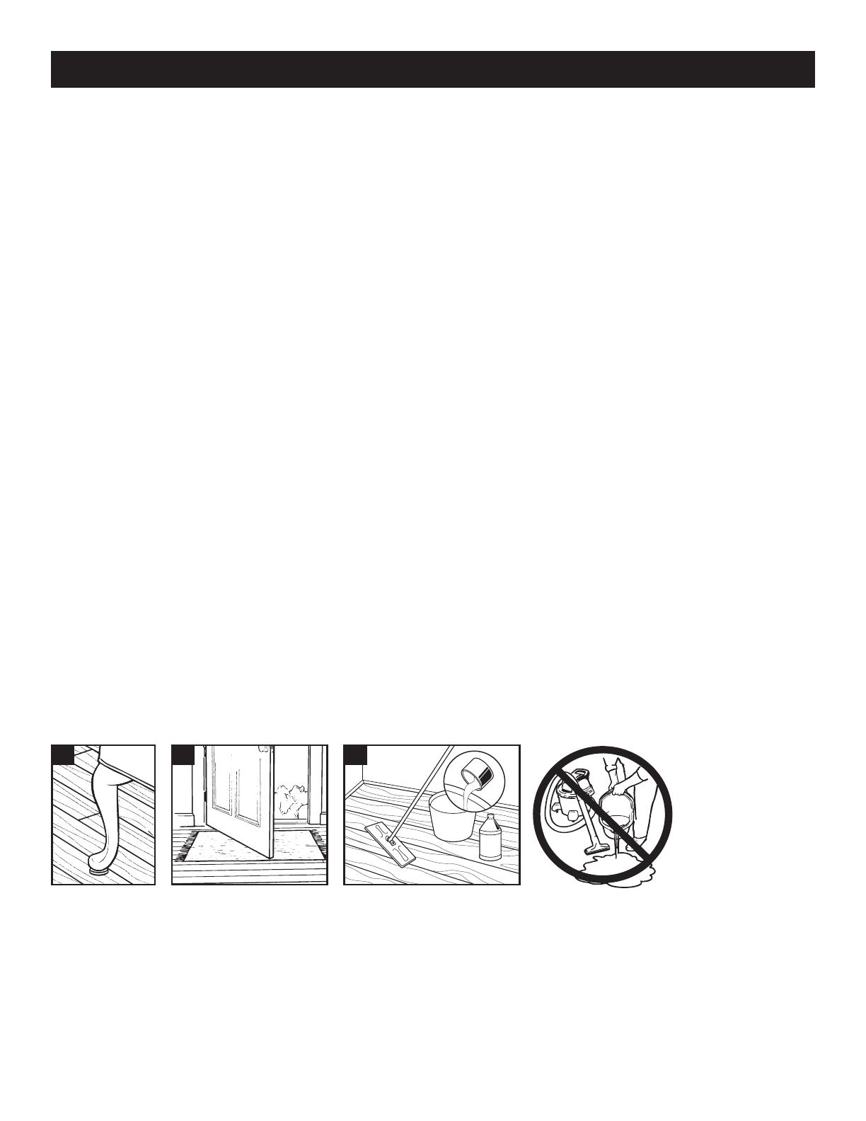
Care and Cleaning
Place felt oor protectors under legs of moveable furniture. Chair casters should be rubber – not plastic or metal. Place
walk-off mats at entrances. Dust mop or damp mop only. NO wet mopping. If needed, use a solution of 1 cup of vinegar
per gallon of water OR 1/3 cup non-sudsing ammonia per gallon of water. Do not use abrasive cleaners, detergents,
soaps, waxes or polishes. Use correct hard surface vacuum tools. DO NOT use rotating beater bars, oor scrubbers,
steamers, jet mops or similar products. DO NOT allow liquids to stand on the oor. Wipe up spills immediately. DO NOT
allow moisture to be on the oor for longer than 30 minutes.
A
B
C
PERGO XP Install Instructions
2019_03_XP_SML


