Page is loading ...

DuraPlus
®
All-Fuel Chimney System
Installation Instructions

A MAJOR CAUSE OF VENT RELATED FIRES IS FAILURE
TO MAINTAIN REQUIRED CLEARANCES (AIR SPACES)
TO COMBUSTIBLE MATERIALS. IT IS OF THE UTMOST
IMPORTANCE THAT DURAPLUS CHIMNEY BE INSTALLED ONLY IN
ACCORDANCE WITH THESE INSTRUCTIONS.
CAME RA-R EADY L OGOTYPE – UL MARK FOR CANADA A ND THE U.S .
These Marks are registered by Underwriters Laboratories Inc.
The mini mum height of the registered trademark symbol ® shall be 3/64 of an inch. When the overall di ameter of the
UL Mark is less than 3/8 of an inch, the trademark symbol may be omitted if it is not legibl e to the naked eye.
The font for all letter forms is Helvetica Condensed Black, except for the trademark symbol ®, which is
Helvetica Condensed Medi um. No other fonts are acceptable.
200-195C 20M/11/97
LISTED
MH7399
NOTE:
Read through all of these instructions before
beginning your installation. Failure to install
as described in this instruction will void the
manufacturer’s warranty, and may have an
effect on your homeowner’s insurance and
UL listing status. Keep these instructions for
future reference. This booklet also contains
instructions for installing a venting system
within an existing masonry chimney, and
for installations passing through a cathedral
ceiling.
Dear Customer, Installer, or End User:
We welcome any comments regarding matters
pertaining to our DuraVent products.
We welcome any ideas, input or complaints
and I’ll make sure that someone responds
directly back to you.
Send your emails to:
If you are searching for tech support or product
information, please call us at 800-835-4429.
Or email us at:

3
CONTENTS
Clearance / Permits / Applications / Notes. . . . . . . . . . . . . . . . . . . . . . . . . . . 4
Chimney Diameter / Chimney Height / Chimney Placement . . . . . . . . . . . . . 5
Chimney Enclosure Requirements / Stove Recommendations. . . . . . . . . . .6
Step-by-Step Directions / Ceiling Supported . . . . . . . . . . . . . . . . . . . . . . . . 7
Offset Elbow Installation. . . . . . . . . . . . . . . . . . . . . . . . . . . . . . . . . . . . . . . . . 12
Offset Chart . . . . . . . . . . . . . . . . . . . . . . . . . . . . . . . . . . . . . . . . . . . . . . . . . . . .13
Extended Roof Bracket Installation. . . . . . . . . . . . . . . . . . . . . . . . . . . . . . . . 14
Roof Supported Installations. . . . . . . . . . . . . . . . . . . . . . . . . . . . . . . . . . . . . 15
Tee Supported Installations . . . . . . . . . . . . . . . . . . . . . . . . . . . . . . . . . . . . . 16
Masonry Fireplace Installations . . . . . . . . . . . . . . . . . . . . . . . . . . . . . . . . . . 18
Zero Clearance Fireplace Installations. . . . . . . . . . . . . . . . . . . . . . . .21
Connection from Appliance to Chimney System . . . . . . . . . . . . . . . . . . . 21
Chimney Maintenance. . . . . . . . . . . . . . . . . . . . . . . . . . . . . .. . . . . . . . . . . . . 22
DuraPlus
®
For the most up-to-date installation instructions, see www.duravent.com
ALL-FUEL CHIMNEY SYSTEM

4
CLEARANCE
Allow at least a 2-inch clearance between
DuraPlus Pipe and any combustible materials.
Where the chimney passes through oors,
joists, or ceilings, Firestop Radiation Shields,
Support Boxes, and Close Clearance Shields
may permit reduced clearances as established
by these parts, or spacers built on to these
parts. The clearance (air space) between
the outer chimney wall, and the inside of the
Support Box, Firestop Radiation Shields,
and Close Clearance Shields, in the cases
of 7 and 8-inch diameter chimney will be less
than 2 inches. Both of these systems have
been extensively tested and evaluated at
these clearances. This reduced clearance is
permissible at these internal locations only.
All other areas require a 2-inch minimum
clearance. Never ll any required clearance
space with insulation or any other materials.
Combustible materials include lumber plywood,
sheetrock, plaster and lath, furniture, curtains,
electrical wiring and building insulation. Keep
single wall stovepipe at least 18 inches
away from combustible materials, unless a
clearance reduction system that is acceptable
to the authority having jurisdiction is used, or
the appliance to be installed is listed and the
instructions specify a different clearance.
PERMITS
Contact your local Building Ofcial or Fire
Ofcial regarding permits, restrictions, and
installation inspections in your area.
DURAPLUS APPLICATIONS
Use DuraPlus with wood stoves, replaces,
furnaces, boilers, water heaters, stoves,
ranges, or other residential-type appliances
fueled by oil, gas, coal, or wood. Do not use
with forced draft positive-pressure appliances.
DuraPlus systems are designed to extend
vertically with a maximum of (2) offsets of 30°
(offset and return). DuraPlus is tested to UL
Test Proceedure 103HT, and listed under UL
Re-examination Service Number MH7399.
Tools You May Need
Hammer Level
Caulking Gun
Plumb Bob
Screwdriver
Tin Snips
Saber or Keyhole Saw
Drill
Materials You May Need
Non-hardening Waterproof Sealant
8 Penny Nails
5/16 inch x 3 inch long Lag Screws
Roong Nails
3/4 inch Galvanized Electrical Conduit (where
the chimney extends 4 feet or more above the
roof)
Safety Equipment
Dependable Ladder
Eye Protection
Proper Gloves and Shoes
INSTALLATION NOTES
Proper planning for your DuraPlus installation
will result in greater safety, efciency, and
convenience, as well as saving time and
money. Use only authorized DuraPlus (SDP)
listed chimney parts. You must use 100%
DuraPlus listed parts to obtain a DuraPlus
listed system. Do not mix parts or try to
match with other products, or use improvised
solutions. Do not install damaged parts. Table
1 lists the authorized components, and their
respective Underwriter’s Laboratory Catalog

5
Numbers. The UL Catalog Numbers will be
referred to within the instructions, as an aid
to assembly, however for ordering, use the
stock numbers shown in the Chimney Products
Catalog. Practice good workmanship. Sloppy
work could jeopardize your chimney’s safety.
Keep electrical wiring and insulation away from
all chimneys and stovepipes.
CHIMNEY DIAMETER
Follow the appliance manufacturer’s
instructions to determine chimney diameter
and clearances between combustible materials
and your heating appliance. Never choose a
chimney with an inside diameter smaller than
the appliance ue gas outlet. To calculate the
chimney’s outside diameter, add 4 inches to
the inside diameter.
CHIMNEY HEIGHT
The National Fire Protection Association
Standard #211 states: “Chimneys shall extend
at least three feet above the highest point
where it passes through the roof of a building,
and at least two feet higher than any portion
of a building within ten feet.” (Figure 1).
DuraPlus may be installed up to 35 feet high.
If a chimney is installed higher than 35 feet, a
supporting Elbow Strap must be placed every
8 feet. If the chimney extends more than 4
feet above the roof, an Extended Roof Bracket
must be used. Subtract 1-1/2 inches from
each Chimney Section’s length to calculate
installed length.
CHIMNEY PLACEMENT
When deciding the location of your chimney,
try to minimize the alteration and reframing of
structural components of the building.
TABLE 1
DURAPLUS (SDP) PARTS WITH UL CATALOG NUMBERS
UL Cat # Part UL Cat # Part
SDP-P Chimney Sections SDP-TS Tee Support Bracket
SDP-T Tee SDP-IS Insulation Shield
SDP-F Flashing SDP-FRS Firestop Radiation Shield
SDP-TF Flat Roof Flashing SDP-SC Storm Collar
SDP-S Flat Ceiling Support Box SDP-WS Wall Strap
SDP-RS Round Ceiling Support Box SDP-ES Elbow Strap
SDP-SB Square Ceiling Support Box SDP-RSA Extended Roof Bracket
SDP-WT Wall Thimble SDP-AP Anchor Plate
SDP-C Chimney Cap
Figure 1
2 FEET MIN. ABOVE HIGHEST
POINT OF ROOF WITHIN
10 FEET
3 FEET MIN.
FROM ROOF
PENETRATION
10 FEET
MINIMUM CHIMNEY HEIGHT

6
CHIMNEY ENCLOSURE
REQUIREMENTS
Through Rooms: Interior chimneys shall be
enclosed where they extend through closets,
storage areas, or habitable spaces where the
surface of the chimney could be contacted by
persons or combustible materials. The space
between the chimney and the enclosure shall
be at least 2 inches. (Figure 2).
Multi-Story: The National Fire Protection
Association Standard #211 states: “ Factory-
built chimneys that pass through oors of
buildings requiring the protection of vertical
openings shall be enclosed with approved
walls having a re reistance rating of not
less than one hour when such chimneys are
located in a building less than 4 stories in
height, and not less than 2 hours when such
chimneys are located in a building more than 4
stories in height.”
Cold Climates: In cold climates, chimneys
mounted on an outside wall should
be enclosed. Exterior chases reduce
condensation and creosote formation, and
enhance draft. Include an access door by the
Tee Cleanout Cap for chimney cleaning. See
gure 23.
STOVE RECOMMENDATIONS
Follow the stove manufacturer’s instructions.
The requirements stated below pertain to
all stoves or other appliances installed with
DuraPlus chimney systems.
Choice: Choose a stove that is listed by a
recognized testing laboratory, is appropriate for
your needs, and is not larger than required.
Installation: Once the chimney system is in place,
install the stove and stovepipe as described in the
stove manufacturer’s instructions, maintaining all
required clearances.
Flues: Connect only one solid fuel appliance
per chimney. Oil-burning appliances are
restricted to one appliance per chimney, as
well.
Operation: Follow the stove manufacturer’s
instructions and safety manual for maximum
efciency and safety. Overring can damage
the stove and stovepipe.
Fuels: Do not burn driftwood, plastic, or
chemically treated wood such as railroad ties.
They are corrosive to your replace, stovepipe
and chimney. Follow the stove manufacturer’s
instructions and safety manual in regards to
fuels. Not all stoves are equipped to burn coal.
Coal with a low sulfur content will reduce the
possibility of corrosion.
Mobile Homes: Please read the stove
manufacturer’s instructions and safety manual
carefully. Not all stoves are listed for use in
mobile homes.
Figure 2
ATTIC
ATTIC INSULATION SHIELD
CEILING
FIRESTOP RADIATION SHIELD
ENCLOSURE MUST HAVE
2 INCHES CLEARANCE
BETWEEN CHIMNEY AND
WALL.
FLOOR
SUPPORT BOX

7
STEP-BY-STEP DIRECTIONS
There are ve general types of DuraPlus
installations:
1. Ceiling-supported
2. Roof-supported
3. Tee-supported (through the wall)
4. Masonry Fireplace
5. Zero-Clearance Fireplace
Review the step-by-step directions before
beginning your installation.
CEILING SUPPORTED
1. Place Appliance: Position the appliance
according to the manufacturer’s instructions.
The ue outlet collar should be placed
between the rafters or joists above, if possible.
2. Frame Support Opening: Drop a plumb
bob to the center of the appliance’s ue outlet
and mark this center point on the ceiling. Refer
to Table 2 for specic framing and clearance
dimensions. Mark appropriate cutting lines
around the center point. Cut a square hole in
the ceiling for a Square Support Box, or a round
hole for a Round Support Box. Frame a level,
square opening centered over the hole which
you have cut. (Figures 3 and 4).
Figure 3
Figure 4
ATTIC
MINIMUM OF 2 INCHES
BELOW FINISHED CEILING
18 INCHES MINIMUM FOR
SINGLE-WALL STOVEPIPE
CAP
SDP-C
STORM COLLAR
SDP-SC
FLASHING
VENTILATED
SDP-SC
CHIMNEY SECTIONS
SDP-P
ATTIC INSULATION SHIELD
SDP-IS
FRAMED
OPENING
SQUARE CEILING
SUPPORT BOX
SDP-SB OR
ROUND CEILING
SUPPORT SDP-RS
14 1/2”
FRAMING
SUPPORT BOX
JOISTS
2 INCHES MINIMUM
BELOW FINISHED
CEILING
14 1/2”
CEILING JOISTS

8
3. Install Support: Slip the Support Box
,(Figure 5), into the framed opening. It must
extend at least 2 inches below the nished
ceiling. Level the Square Support Box and
nail it to the framing using at least two 8-penny
nails per side. The two Trim Frames are
positioned as shown, and screwed through
the ceiling and into the framing members with
(6) 1-1/4 inch long round-head wood screws.
(Figure 6). The bottom of the Round Support
must also be at least 2 inches below the
nished ceiling. Trim for the Support Boxes
is “U-shaped” . The trim pieces are adjusted
to accommodate the Square Support Box, and
screwed into the framing, using wood screws.
A completed Square Support Box installed in
a cathedral ceiling with the “U-shaped” trim is
also shown in Figure 6. Trim kits are available
in brass, to enhance the appearance of the
various Support Boxes and Trim Frames .
Where the chimney passes through additional
oors and ceilings, install Firestop Radiation
Shields. Where the chimney passes through
an attic, Firestop Radiation Shields and
Insulation Shields must be installed.
4. Frame Openings: Frame openings in
each ceiling or oor above the Support Box.
(Figure 7). These openings are to hold the
Firestop Radiation Shields and Attic Insulation
Shields. Locate each opening by dropping a
plumb bob to the four corners of the opening
below. Maintain the minimum clearances and
Figure 5
ROUND CEILING SUPPORT
SDP-RS
FLAT SUPPORT BOX
SDP-S
Figure 6
WOOD SCREW (6 REQ)
WOOD SCREW (8 REQ)
SUPPORT BOX IN
CATHEDRAL CEILING
WITH TRIM FRAME IN
PLACE
ROUND CEILING
SUPPORT WITH TRIM
PLATES IN PLACE
ATTIC
Figure 7
2 INCH MIN
CLEARANCE
INSIDE OF
ENCLOSURE
FRAMED
ENCLOSURE
MIN OF 2 INCHES
BELOW FINISHED
CEILING
SECOND STORY
CAP SDP-C
STORM COLLAR
SDP-SC
FLASHING
VENTILATED
SDP-SC
CHIMNEY SECTIONS
SDP-P
ATTIC INSULATION
SHIELD SDP-IS
FRAMED
OPENING
SQUARE CEILING SUPPORT
BOX SDP-SB OR ROUND
CEILING SUPPORT SDP-RS
CHIMNEY SECTIONS
SDP-P
FIRESTOP
RADIATION SHIELD
SDP-IS

9
through a Firestop Radiation Shield, a ceiling,
and into an attic. The other is a multi-story
building where the chimney passes through a
Firestop Radiation Shield, through a ceiling,
into another story, and then into an attic.
Each of these require a different conguration
of the Firestop Radiation Shield. Figure 7
dimensions as specied in Table 2. If Elbows
must be used to avoid an obstruction, refer to
the offset elbow installation section.
5. Cut Roof Opening: Cut an opening in the
roof directly above the opening below, and
at least 4 inches larger than the chimney’s
outside diameter to provide at least a 2-inch
clearance all around the chimney. If the
installation is located between rafters that
are 16 inches on center, Close Clearance
Shields (a sheet metal product fabricated by
DuraVent), may be used to avoid structural
reframing. (Figure 8). The 2-inch minimum
clearance to combustibles is not required when
the chimney passes through Close Clearance
Shields. When using Close Clearance Shields,
Ventilated Flashing must be installed. Refer to
Figure 10, which pictures both Ventilated and
Non-ventilated Flashing.
6. Install Firestop Radiation Shield: One
of two possible situations exist for installing
the Firestop Radiation Shield. One is a
two- story dwelling where the chimney passes
TABLE 2
FRAMING FOR SQUARE SUPPORT BOXES, ROUND SUPPORT BOXES AND WALL THIMBLES
SQUARE SUPPORT BOXES
Chimney inside diameter 6 INCHES 7 INCHES 8 INCHES
Framed opening inside dimensions 14 ½ x 14 ½ 14 ½ x 14 ½ 14 ½ x 14 ½
ROUND SUPPORT BOXES
Chimney inside diameter 6 INCHES 7 INCHES 8 INCHES
Framed opening inside dimensions 14 ½ x 14 ½ 14 ½ x 14 ½ 14 ½ x 14 ½
WALL THIMBLES
Chimney inside diameter 6 INCHES 7 INCHES 8 INCHES
Framed opening inside dimensions 14 ½ x 14 ½ 14 ½ x 14 ½ 14 ½ x 14 ½
FIRESTOP RADIATION SHIELD
Chimney inside diameter 6 INCHES 7 INCHES 8 INCHES
Framed opening inside dimensions 14 ½ x 14 ½ 14 ½ x 14 ½ 14 ½ x 14 ½
Figure 8
14 INCHES 14 INCHES
14 INCHES
X
X
CUT PANEL’S TO
ROOF PITCH LINE
ROOF PITCH LINE

10
illustrates the two-story building. In the case
of the two-story installation, the base of the
Firestop Radiation Shield is nailed to the top
of the framing, with the pan (the depressed
portion of the base), facing downwards. For
the multi-story installation, the base is nailed to
the bottom of the framing with the pan facing
upwards. The cylindrical component of the
Firestop Radiation Shield is then slipped down
through the base from the top until it rest on
the bead. (Figure 9). Refer to Table 2 for the
framing requirements.
7. Assemble Chimney Sections: Lower
and seat the female end of the rst Chimney
Section in the Support Box. (Figure 11). It
will twist-lock onto the male end of a Low
Prole Starter Section, which is a component
of the Support Box. Turn Pipe Sections
clockwise, rmly to lock them together. Sheet
metal screws may be used to reinforce the
connection, however they are not normally
required. Screws are only acceptable in the
outer liner.
8. Install Attic Insulation Shield: Install
the Attic Insulation Shield where the chimney
passes into an attic. It’s purpose is to prevent
debris and insulation from getting too close to
the chimney. (Figure 12). An installed Attic
Insulation Shield is 14 inches high. In attic
areas where this shield won’t t, a Square
Support Box, (which is available in heights
up to 36 inches), can be used instead of an
Attic Insulation Shield, provided it reaches
through the roof; refer to the Roof Supported
Installation section on page 14. If the
chimney is fully enclosed through the attic,
an Insulation Shield is not required, however,
again, Ventilated Flashing must be used.
Where the chimney passes into the attic,
install the Attic Insulation Shield as follows:
a. If the Firestop Radiation Shield extends
above the attic oor, no modications are
Figure 9
FRAMING
NAILS (AT LEAST 2 PER SIDE)
FIRESTOP RADIATION SHIELD SDP-FRS
NAILS (AT
LEAST
2 PER
SIDE)
FRAMING
FIRESTOP RADIATION
SHIELD SDP-FRS
Figure 10
Figure 11
VENTILATED FLASHING
CHIMNEY SECTION
SDP-P
SUPPORT BOX
SDP-S, SDP-RS, SDP-SB
MULTI-STORY GOING
INTO NEXT FLOOR
TWO-STORY GOING
INTO ATTIC

11
necessary. The Firestop Radiation Shield will
t inside the Attic Insulation Shield.
b. Assemble Chimney Sections until at least
18 inches of chimney extends above the
Firestop Radiation Shield.
c. Slip the Insulation Shield over the Chimney
and Firestop Radiation Shield until the base
sits squarely on the framed opening. (Figure
7).
d. Nail the Insulation Shield to the top of the
framed opening with at least two 8-penny nails
per side. (Figure 12).
e. Wrap the Collar around the chimney and
fasten it loosely. Slide the Collar down to meet
the Insulation Shield. Slip the tab through the
adjacent slot and fold it back to tighten the
Collar. (Figure 13).
9. Attach Flashing: In new construction,
assemble the Chimney Sections to a point
above the roof, then slip the Flashing over
the chimney. On an existing roof, center
and install the Flashing before extending
the chimney above the roof. Allow space
to permit sliding the next Chimney Section
up through the Flashing. Always insure the
chimney remains vertical, and that at least a
2-inch clearance to combustible materials is
maintained all around. Install the upper edge
of the Flashing under the roong. Nail to the
roof along the upper edge and the upper half
on each side with 1-inch roong nails. Do
not nail the lower edge of the Flashing, or the
lower half of the sides. (Figure 14). Seal all
nail heads with a non-hardening waterproof
sealant. On at or tarred and graveled roofs,
nail and seal the Flat Roof Flashing to the roof
on all sides with roong compound. Do not put
screws through the Flashing into the Chimney
Pipe.
10. Finish Top: Apply a non-hardening
waterproof sealant around the chimney at the
point where the Storm Collar will meet the
Figure 12
WARNING: IF CHIMNEY
IS ENCLOSED IN ATTIC
AREA, YOU MUST USE
VENTILATED FLASHING.
SDP-IS
Figure 13
Figure 14
1 INCH ROOFING
NAILS ALONG TOP OF
FLASHING
PUSH COLLAR
DOWN TO
FLASHING AND
SEAL WITH
NON-HARDENING
SEALANT.
(SEALANT SHOWN
IN HEAVY LINE)
STORM COLLAR
SDP-SC
FLASHING
SDP-F
SDP-TF

12
chimney above the Flashing, and also along
the vertical seam of the chimney pipe, which
is exposed to the weather. (Figures 14 and
15). Slide the Storm Collar down over the
chimney to the top of the Flashing. Tighten
and seal the Storm Collar against the sealant.
After installing sufcient Chimney Sections to
meet the height requirement, (Figure 1), snap
the Chimney Cap onto the top of the chimney.
The Chimney Cap can be removed for
chimney cleaning as described in the Chimney
Maintenance section of the instructions. Use
an Extended Roof Bracket if the chimney
extends more than 4 feet above the roof.
(Figures 18, and 19) in the Extended Roof
Bracket section. If you are located in heavy
snow country, a “splitter” should be fabricated
from heavy gauge sheet metal, and installed.
(Figure 16). This will route the snow around
the chimney, and protect it. This item is not
furnished by DuraVent.
11. Enclosures: Enclose chimneys where
they pass through occupied spaces, including
closets. Always maintain at least a 2 inch
clearance between the chimney and any
combustible surface. Interior enclosures may
be constructed with standard framing and
sheathed with sheetrock or plywood. Use Wall
Straps, if necessary, to maintain a minimum of
2 inches of air space between the chimney and
combustible materials.
OFFSET ELBOW INSTALLATION
Elbows are manufactured in 15° and 30°
angles measured from the vertical. A 30°
Elbow is the largest that can be used in an
offset. A 30° Elbow may not be combined with
a 15° Elbow to make a 45° offset for example.
Avoid Elbows if possible, since a totally vertical
chimney is more efcient. When Elbows
are necessary to avoid obstructions such as
rafters, ridgepoles, or joists, use no more than
CAP
SDP-C
Figure 15
APPLY SMALL BEAD OF NON-HARDENING
SEALANT ALONG SEAM SEAM OF CHIMNEY
PIPE SECTION
Figure 16
SPLITTER
SPLITTER
TOP VIEW
Figure 17
SDP-ES
SDP-E 15º / 30º
NOT MORE THAN 48 INCHES
SDP-P
RISE
SDP-P
OFFSET

13
2 pairs of Elbows (4 elbows total) in any one
chimney system.
1. Attach Elbows: Attach Elbows to Chimney
Sections or other Elbows by twisting clockwise
until they lock rmly. Attach one Elbow to the
Chimney Section below, and align it for the
offset. If the needed direction of the Elbow
is different than the fully locked position, the
Elbow can be rotated to desired direction
and can be secured to pipe section with a
minimum of (4) sheet metal screws. Do not
penetrate the inner wall. Refer to Table 3 to
determine the required offset length and attach
an appropriate length (or lengths) of Chimney
Section(s) above the Elbow. Do not exceed
the maximum lengths between the Elbows
specied in Table 3. Attach the second Elbow
above the Chimney Section to complete the
offset. (Figure 17).
2. Secure Offset: Place the Elbow Strap’s
band around the angled portion of the top
Elbow, then tighten the nut and bolt until the
clamp is rm. Wrap the Elbow Strap end
over an adjacent joist or rafter and secure it
with at least two 8-penny nails. Do not add
more Chimney Sections until the Elbows are
supported. Be sure that the chimney remains
vertical. If the total length of the Chimney
Sections between the two Elbows exceeds 3
feet, install a second Elbow Strap around the
center of the Chimney Section(s).
TABLE 3
DURAPLUS (SDP) OFFSET CHART
OFFSET
RISE
SIZE 6” DIAMETER 7” DIAMETER 8” DIAMETER
Elbow
Degrees
Chimney
Section
Offset
Inches
Rise
Inches
Offset
Inches
Rise
Inches
Offset
Inches
Rise
Inches
15° 0”
1 ⁄” 12” 1 ⁄” 13 ⁄” 1 ⁄” 13 ⁄”
15° 12”
4 ⁄” 23 ½” 4 ⁄” 20 ⁄” 4 ⁄” 23 ⁄”
15° 24”
7 ⁄” 34” 7 ⁄” 35 ⁄” 6 ⁄” 35 ⁄”
15° 36”
10 ⁄” 45 ⁄” 10 ⁄” 46 ⁄” 9 ⁄” 47”
15° 24”+24”
13 ⁄” 55 ⁄” 13 ⁄” 57” 12” 57 ⁄”
30° 0”
3 ⁄” 14 ⁄” 3 ⁄” 14 ⁄” 3 ⁄” 14 ⁄”
30° 12”
9” 24” 9” 24” 9” 24”
30° 24”
15” 33 ⁄” 15” 33 ⁄” 14 ⁄” 34 ⁄”
30° 36”
21” 44” 21” 43 ⁄” 20 ⁄” 44 ⁄”
30° 24”+24”
26 ⁄” 53” 26” 52 ⁄” 25 ⁄” 53 ⁄”

14
EXTENDED ROOF BRACKET
INSTALLATION
If the chimney extends more than 4 feet above
the rooine, an Extended Roof Bracket must
be installed at every 4-foot increment of height
above the rooine, leaving no more than 4 feet
extending above the last pipe band.
1. Mount Pipe Band: Slip the Pipe Band
around the chimney and secure by tightening
the nut and bolt.
2. Install Roof Brackets: Measure from the
Pipe Band to the points where the conduit will
meet the roof, and form approximately a 60°
angle with the chimney, and with each other.
(Figures 18 and 19). Cut 2 pieces of 3/4 inch
thin wall galvanized steel electrical conduit,
(or rigid galvanized tubing) to these lengths.
The conduit is not furnished by DuraVent,
and must be locally procured. Mount the two
Roof Brackets where the conduit meets the
roof, using 6 roong nails per bracket. Seal
the nail heads carefully with a non-hardening,
waterproof sealant.
3. Attach Conduit: Flatten 1 inch and drill
a 1/4-inch hole at each end of both pieces of
conduit. Bolt each conduit to the Pipe Band
and Roof Brackets with the nuts and bolts
provided.
Figure 20
A MINIMUM OF 2 INCHES
BELOW FINISHED CEILING
18 INCHES MINIMUM FOR
SINGLE-WALL STOVEPIPE
CAP
SDP-C
STORM COLLAR
SDP-SC
VENTILATED FLASHING
SDP-F
CHIMNEY SECTIONS
SDP-P
ROOF
FRAMED OPENING
SQUARE CEILING SUPPORT
BOX SDP-SB
PUSH SUPPORT BOX UP
THROUGH ROOF, TRIM
AND FOLD BACK EXCESS
AS SHOWN IN FIG. 22
Figure 18
EXTENDED
ROOF
BRACKET
SDP-RSA
CHIMNEY SECTION
SDP-P
3/4 INCH THIN-WALL
GALVANIZED ELECTRICAL
CONDUIT (NOT FURNISHED)
60º
Figure 19
CHIMNEY CAP SDP-C
EXTENDED ROOF BRACKET SDP-RSA
STORM COLLAR SDP-SC
FLASHING SDP-F,
SDP-TF
60º
CONSISTS OF: (1) PIPE BAND, (2) ROOF BRACKET CONNECTED
WITH 3/4 INCH THIN-WALL GALVANIZED ELECTRICAL CONDUIT. (NOT
FURNISHED BY DURAVENT). FLATTEN ENDS AND BOLT TO PIPE BAND
AND BRACKET.
NOTE: IF
DIMENSION ‘A’
IS GREATER
THAN 4-FEET,
EXTENDED
FOOF BRACKET
MUST BE USED.
A

15
ROOF SUPPORTED
INSTALLATIONS
Use only where a leveled Square Support Box
will extend at least 2 inches below the ceiling
(on the low side), while the top edge at least
covers the edge of the roof’s decking material.
Square Support Boxes are available in 11
inch, 24 inch, and 36 inch heights. Mobile
home chimney installations are roof supported,
and use Ventilated Flashings. Do not seal
openings.
Figure 21
2 INCHES MINIMUM
18 INCHES MINIMUM FOR
SINGLE-WALL STOVEPIPE
CAP
SDP-C
STORM COLLAR
SDP-SC
VENTILATED FLASHING
SDP-F
CHIMNEY SECTIONS
SDP-P
SQUARE CEILING SUPPORT
BOX SDP-SB
PUSH SUPPORT BOX UP
THROUGH ROOF, TRIM
AND FOLD BACK EXCESS
AS SHOWN IN FIG. 22
Figure 22
SUPPORT BOX
SDP-SB
1. Place Appliance: Place the appliance in it’s
proper location, referring to the manufacturer’s
instructions as to allowable distances from
combustibles, etc.
2. Cut Openings: Cut a roof opening directly
above the appliances’ ue outlet collar, just
as in a Ceiling-Supported Installation (Steps 1
thru 5). If a separate ceiling and roof exists,
as shown in Figure 20, (Low Attic), rst cut
and frame a ceiling opening as described
in Ceiling-Supported Installations (Step 2).
Refer to Table 2 for clearance and framing
specications. If it is desired to install through
a cathedral ceiling (Figure 21), then the hole is
cut in the roof.
3. Install Support Box: Slip the Square
Support Box into the framed opening so it
projects at least 2 inches below the nished
ceiling and rafters, and extends above the
ceiling to framing or decking materials to
which it will be nailed. Level the Support Box,
and slit the corners to the rooine where they
extend beyond it. Bend the aps (created
by the slitting) ush with the roof, and nail
the Support Box to the roof or framing with
at least two 8-penny nails per side. (Figure
22). Screw the trim sections into the ceiling.
(Figure 6).

16
4. Complete Installation: Refer to Steps 8,
and 9, in the Ceiling Supported Installation
section, to complete the Roof-Supported
installation.
TEE-SUPPORTED INSTALLATIONS
Tee-Supported installations are used when
passing through a wall to an outside chimney.
The required parts and general conguration
are as shown in Figures 23, and 24.
1. Place Appliance: Position the appliance
according to the manufacturer’s instructions.
2. Cut and Frame Opening: Cut
14-1/4 inch diameter holes in the inner and
outer walls. The center of these holes should
be aligned with the center of the stove’s ue
outlet collar. For new construction, prior to
sheetrock or other covering of the wall studs is
applied, frame a square opening between the
studs, as specied in Table 2. ( Figure 25).
Should it be necessary to go through concrete,
masonry, or cinder-block, a 14-1/4 inch
Figure 25
14 1/2”
14 1/2”
Figure 24
PIPE SECTION
6-INCH OR 9-INCH
SDP-P
WALL THIMBLE
SDP-WT
PIPE
SDP-P
TEE
SDP-T
TEE SUPPORT
SDP-TS
TEE CAP
(COMPONENT OF
SDP-T)
TEE CAP
COMPONENT OF
SDP-T
REMOVABLE
TRAY
(COMPONENT
OF SDP-TS)
5/16 X 3” LAG
SCREWS
(6 REQ) NOT
FURNISHED
Figure 23
WARNING:
VENTILATED
FLASHING MUST
BE USED WITH
ENCLOSURES.
ALLOW 1/2 INCH AIR
SPACE BETWEEN BASE
OF FLASHING OR COVER
AND ENCLOSURE
FRAMING.
TYPICAL
THRU-THE-WALL
TEE- SUPPORTED
INSTALLATION
ACCESS DOOR
FOR CLEANING
FRAMED
EXTERIOR
ENCLOSURE

17
diameter hole must be cut through the wall.
3. Install Wall Thimble: Insert the black
section of the Wall Thimble into the opening
in the wall from inside the room, and align
the nail holes with the studs. (Figure 26).
Do not nail the black thimble section at this
time. Attach the Tee to a 9-inch or 12-inch
Chimney Section by twisting until it is rmly
locked. If the wall is less than 6 inches thick,
use a 9-inch Chimney Section; if the wall is
between 6 and 9 inches thick, use a 12-inch
Chimney Section. From outside the building,
insert the Chimney Section into the hole until
the vertical part of the Tee is 2 inches away
from the outside of the wall, and the black
portion of the Wall Thimble and the Chimney
Section protrude into the room at least 2
inches. IMPORTANT: In order to make a
safe connection, the female end of the
Chimney Section must fully contact the
inside face of the Wall Thimble. Remove the
Figure 26
5/16 X 3” LAG
SCREWS (6 REQ)
NOT FURNISHED
14 1/2”
14 1/2”
8-PENNY NAILS (4) REQ
SHIMS TO
MAINTAIN
CIRCULARITY
OF THIMBLE
(2) REQ (NOT
FURNISHED,
MAY BE MADE
OF WOOD)
2 INCHES MINIMUM
DURA PLUS
CHIMNEY PIPE
TEE
SDP-T
2 INCHES MINIMUM
CLEARANCE
INTERIOR
PORTION OF
WALL THIMBLE
SDP-WT (BLACK)
OUTSIDE
VIEW FROM OUTSIDE
Figure 27
NOTE: IF SYSTEM EXITS
THRU WALL INTO GARAGE, AN
ENCLOSURE ISREQUIRED.
VENTILATED FLASHING
MUST BE USED
2 INCHES MINIMUM
ENCLOSURE
GARAGE
2 INCHES
MINIMUM
ACCESS DOOR
FOR CLEANING
Tee and Chimney Section from the wall, and
nail the Wall Thimble’s black section to the
studs with four 1-inch roong nails. If the Wall
Thimble is going through a concrete wall, and
no framing members are available to which to
nail the black portion of the Wall Thimble to,
use masonry anchors to attach it. If a Tee-
Supported installation is being installed in a
garage, it must be enclosed. (Figure 27).
4. Seal Outside: From the outside, insert
the galvanized section of the Wall Thimble
through the wall and into the black section.
If it does not reach the black section, an
extension tube can be locally made from .018”
thick galvanized steel. Seal the ange of the
galvanized portion of the Wall Thimble to the
outside wall, using non-hardening waterproof
sealant, and fasten it to the wall with screws.
From the outside, slip the Chimney Section,
which is attached to the Tee, into the Thimble.
NEVER INSTALL SINGLE WALL STOVEPIPE
THROUGH THE WALL THIMBLE!
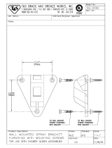
5. Install Tee Support: Remove the two
screws from the Tee Cleanout Cap, and detach
it from the Tee. Attach the Tee Support Straps
to the base with the nuts and bolts provided.

18
Use (2) 5/16 inch, 3-inch long lag screws to
attach the straps to the wall. Replace the Tee
Cleanout Cap and screws, once the Tee is
installed.
6. Complete Chimney: Attach the Chimney
Sections as in Step 7 of the Ceiling Supported
Installation section. Secure the chimney to
the wall with Wall Straps at 4-foot intervals
to maintain at least 2 inches of clearance to
combustible materials. Slip the Wall Straps
around the chimney, tighten the bolts, and
fasten the Wall Straps to the wall with (2)
5/16-inch, 3-inch long lag screws. Snap the
Chimney Cap into the top of the chimney,
once it is at the height specied in Figure 1. If
the chimney penetrates an overhang, frame
for at least 2 inches of clearance, and install
Figure 28
WALL STRAP
ALLOW A MINIMUM OF
2 INCHES AIR SPACE
ON ALL SIDES
2 INCHES MINIMUM
2 INCHES MINIMUM
a Flashing and Storm Collar as described
in Steps 8, 9 and 10 for Ceiling Supported
Installations. Another option is to cut away
the overhang for a 2-inch clearance. (Figure
28). If the chimney extends more than 4 feet
above the top Wall Band, or Flashing, use an
Extended Roof.
7. Install Chase Cover. If a chase enclosure
has been constructed, installing the chase
cover requires some special considerations.
The chase must be ventilated at the top
and a 1/2-inch air gap must be established
between the cover, and the framed chase
top. In addition, a 1/2-inch air gap should
exist between the hole in the cover, and the
Chimney Pipe Sections. Figure 29 displays
in some detail, how these air gaps are
established with locally fabricated spacers and
covers. These are not furnished by DuraVent,
but may be made from 28 gage or heavier
sheet metal. Should the installer elect to use
Flat Roof Flashing, (which is a stock item), the
air spaces are still required. When installing
the Storm Collar, do not push it down all the
way to the cover, but allow an air space for
ow between the Chimney Pipe and the hole
in the cover.
MASONRY FIREPLACE
INSTALLATIONS
1. Determine Chimney Size: Use Table 4
to determine the correct diameter chimney for
your replace.
2. Mount Anchor Plate: Chimneys for
masonry replaces begin with an Anchor Plate.
Center the Anchor Plate on a brick or concrete
base over the masonry ue opening. Seal the
Anchor Plate with a high-temperature sealant,
and secure with (4) 1/4-inch masonry anchors.
(Figure 30). Be sure it is level. The Anchor
Plate is available in two styles. One contains
the perforated Starter Section, which is used

19
in the event the chimney is to be enclosed.
The other is a at plate, to be used in cases
when the chimney is not enclosed.
3. Attach Chimney: Place the rst Chimney
Section over the ange on the Anchor Plate
with the arrows pointing up. Drill 1/8-inch
diameter holes through the outer sleeve of the
Chimney Section which match the location of
the corresponding holes in the Anchor Plate.
Secure the Chimney Section to the Anchor
Plate with #8 self-tapping sheet metal screws.
4. Finish Chimney: Install the rest as directed
in the Ceiling Supported Installation section,
Steps 4 through 10. Refer to Figure 1 and
Table 4 for chimney height requirements.
Always maintain at least 2 inches of clearance
to combustible materials, and enclose the
chimney where it passes through occupied
areas. Use a Wall Strap for every four feet of
chimney height.
Figure 29
1/2 INCH AIR SPACE
1/2 INCH AIR SPACE ESTABLISHED
BY SPACERS
12 INCH MINIMUM
FLAT ROOF FLASHING
FRAMED
CHASE
ENCLOSURE
NAIL (AS REQ)
CAP
SDP-C
STORM COLLAR
(SDP-SC)
FLAT ROOF FLASHING
(SDP-TF)
MUST BE VENTILATED
SPACERS LOCALLY
FRABRICATED (NOT
FURNISHED BY DURAVENT)
CHIMNEY
SECTIONS
SDP-P
1/2
Figure 30
CHIMNEY PIPE
SECTION SDP-P
LOW-PROFILE
STARTER SECTION
(REQUIRED IF
CHIMNEY IS
ENCLOSED)
MASONRY
ANCHORS
(4) REQ (NOT
FURNISHED)
EXISTING
MASONRY
CHIMNEY
HI-TEMP
SEALANT
SHEET
METAL
SCREWS (4)
REQ
ANCHOR PLATE
SDP-AP

20
TABLE 4
/