Toro Z597-D Z Master, With 60in TURBO FORCE Side Discharge Mower User manual
- Category
- Lawnmowers
- Type
- User manual
This manual is also suitable for

Form No. 3357-979 Rev A
Z597-D Z Master® with 60in
or 72in TURBO FORCE® Side
Discharge Mower
Model No. 74268CP —Serial No. 270000001 and Up
Model No. 74269CP —Serial No. 270000001 and Up
Register your product at www.Toro.com Original Instructions (EN)

Warning
CALIFORNIA
Pr oposition 65 W ar ning
Diesel engine exhaust and some of its
constituents ar e kno wn to the State of
Calif or nia to cause cancer , bir th defects, and
other r epr oducti v e har m.
Important: T his engine is not equipped
with a spar k ar r ester muf fler . It is a
violation of Calif or nia Public R esource Code
Section 4442 to use or operate the engine
on an y f or est-co v er ed, br ush-co v er ed, or
g rass-co v er ed land. Other states or federal
ar eas may ha v e similar la ws.
T his spark ignition system complies with Canadian
ICES-002
T he enclosed Engine Owner’ s Man ual is
supplied f or inf or mation r egarding the US
En vir onmental Pr otection Agency (EP A) and
the Calif or nia Emission Contr ol R egulation of
emission systems, maintenance, and w ar ranty .
R eplacements may be order ed thr ough the
engine man uf actur er .
Introduction
R ead this infor mation carefully to lear n ho w to
operate and maintain y our product properly and
to a v oid injur y and product damag e . Y ou are
responsible for operating the product properly
and safely .
Y ou ma y contact T oro directly at www .T oro .com
for product and accessor y infor mation, help
finding a dealer , or to register y our product.
W henev er y ou need ser vice , g en uine T oro par ts ,
or additional infor mation, contact an A uthorized
Ser vice Dealer or T oro Customer Ser vice and ha v e
the model and serial n umbers of y our product
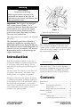
ready . Figure 1 identifies the location of the model
and serial n umbers on the product. W rite the
n umbers in the space pro vided.
Figure 1
1. Model and serial number location
Model No.
Serial No.
T his man ual identifies potential hazards and has
safety messag es identified b y the safety aler t
symbol ( Figure 2 ), whic h signals a hazard that ma y
cause serious injur y or death if y ou do not follo w
the recommended precautions .
Figure 2
1. Safety alert symbol
T his man ual uses 2 other w ords to highlight
infor mation. Impor tant calls attention to special
mec hanical infor mation and Note emphasizes
g eneral infor mation w or th y of special attention.
Contents
Introduction . . . . . . . . . . . . . . . . . . . . . . . . . . . . . . . . . . . . . . . . . . . . . . . . . . . . . . . 2
Safety . . . . . . . . . . . . . . . . . . . . . . . . . . . . . . . . . . . . . . . . . . . . . . . . . . . . . . . . . . . . . . . . . . 4
Safe Operating Practices . . . . . . . . . . . . . . . . . . . . . . 4
Slope Char t . . . . . . . . . . . . . . . . . . . . . . . . . . . . . . . . . . . . . . . . . 7
Safety and Instr uctional Decals . . . . . . . . . . . . 8
Product Ov er view . . . . . . . . . . . . . . . . . . . . . . . . . . . . . . . . . . . . . . . . . . . . . 15
Controls . . . . . . . . . . . . . . . . . . . . . . . . . . . . . . . . . . . . . . . . . . . 15
Operation . . . . . . . . . . . . . . . . . . . . . . . . . . . . . . . . . . . . . . . . . . . . . . . . . . . . . . . . . . 16
Adding Fuel . . . . . . . . . . . . . . . . . . . . . . . . . . . . . . . . . . . . . . 16
Chec king the Engine Oil Lev el . . . . . . . . . . . 17
© 2007—The Toro® Company
8111 Lyndale Avenue South
Bloomington, MN 55420
2
Contact us at www.Toro.com.
Printed in the USA.
All Rights Reserved

Switc hing the Fuel T anks . . . . . . . . . . . . . . . . . . . 17
Using the R ollo v er Protection
System (R OPS) . . . . . . . . . . . . . . . . . . 17
T hink Safety First . . . . . . . . . . . . . . . . . . . . . . . . . . . . . . 18
Understanding the A udible
Alar ms . . . . . . . . . . . . . . . . . . . . . . . . . . . . . . 19
Operating the P arking Brak e . . . . . . . . . . . . . . 20
Star ting and Stopping the
Engine . . . . . . . . . . . . . . . . . . . . . . . . . . . . . . 20
Operating the P o w er T ak e Off
(PTO) . . . . . . . . . . . . . . . . . . . . . . . . . . . . . . . 22
T he Safety Interloc k System . . . . . . . . . . . . . . . 22
Dri ving F orw ard or Bac kw ard . . . . . . . . . . . . 23
Stopping the Mac hine . . . . . . . . . . . . . . . . . . . . . . . . 24
Adjusting the Control Lev er
R esistance . . . . . . . . . . . . . . . . . . . . . . . . . 24
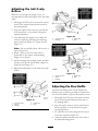
Adjusting the Height-of-Cut . . . . . . . . . . . . . . 24
Using the Lift Assist Lev er . . . . . . . . . . . . . . . . . 24
Adjusting the Anti-Scalp
R ollers . . . . . . . . . . . . . . . . . . . . . . . . . . . . . . . 25
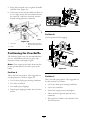
Adjusting the Flo w Baffle . . . . . . . . . . . . . . . . . . . 25
P ositioning the Flo w Baffle . . . . . . . . . . . . . . . . 26
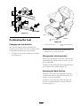
P ositioning the Seat . . . . . . . . . . . . . . . . . . . . . . . . . . . 27
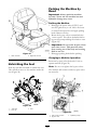
Unlatc hing the Seat . . . . . . . . . . . . . . . . . . . . . . . . . . . . 28
Pushing the Mac hine b y Hand . . . . . . . . . . . . 28
Using the Side Disc harg e . . . . . . . . . . . . . . . . . . . 29
T ranspor ting Mac hines . . . . . . . . . . . . . . . . . . . . . . 29
Loading Mac hines . . . . . . . . . . . . . . . . . . . . . . . . . . . . . 29
Using the Z Stand® . . . . . . . . . . . . . . . . . . . . . . . . . . . 30
Operating Tips . . . . . . . . . . . . . . . . . . . . . . . . . . . . . . . . . . 31
Maintenance . . . . . . . . . . . . . . . . . . . . . . . . . . . . . . . . . . . . . . . . . . . . . . . . . . . . . . 33
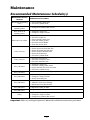
R ecommended Maintenance
Sc hedule(s) . . . . . . . . . . . . . . . . . . . . . . . . . . . . . . . 33
Lubrication . . . . . . . . . . . . . . . . . . . . . . . . . . . . . . . . . . . . . . . . . . . . . . . . 34
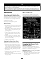
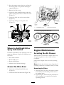
Greasing and Lubrication . . . . . . . . . . . . . . . . . . . 34
Greasing the Mo w er Dec k and Belt
Idlers . . . . . . . . . . . . . . . . . . . . . . . . . . . . . . . . . 34
W here to Add Light Oil or Spra y
Lubrication . . . . . . . . . . . . . . . . . . . . . . . . 35
Grease the Idler Ar ms . . . . . . . . . . . . . . . . . . . . . . . . 35
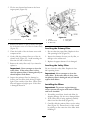
Engine Maintenance . . . . . . . . . . . . . . . . . . . . . . . . . . . . . . . . . . 35
Ser vicing the Air Cleaner . . . . . . . . . . . . . . . . . . . 35
Ser vicing the Engine Oil . . . . . . . . . . . . . . . . . . . . 37
Fuel System Maintenance . . . . . . . . . . . . . . . . . . . . . . . . . . 39
Ser vicing the Fuel Filter . . . . . . . . . . . . . . . . . . . . . 39
Ser vicing the Fuel T ank . . . . . . . . . . . . . . . . . . . . . . 40
Electrical System Maintenance . . . . . . . . . . . . . . . . . . . 40
Ser vicing the Batter y . . . . . . . . . . . . . . . . . . . . . . . . . . 40
Ser vicing the Fuses . . . . . . . . . . . . . . . . . . . . . . . . . . . . 42
Dri v e System Maintenance . . . . . . . . . . . . . . . . . . . . . . . . . 42
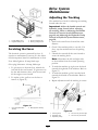
Adjusting the T rac king . . . . . . . . . . . . . . . . . . . . . . . 42
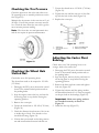
Chec king the Tire Pressure . . . . . . . . . . . . . . . . . 43
Chec king the W heel Hub Slotted
Nut . . . . . . . . . . . . . . . . . . . . . . . . . . . . . . . . . . . 43
Adjusting the Caster Pi v ot
Bearing . . . . . . . . . . . . . . . . . . . . . . . . . . . . . . 43
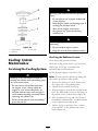
Cooling System Maintenance . . . . . . . . . . . . . . . . . . . . . 44
Ser vicing the Cooling System . . . . . . . . . . . . . 44
Brak e Maintenance . . . . . . . . . . . . . . . . . . . . . . . . . . . . . . . . . . . . 45
Adjusting the P arking Brak e . . . . . . . . . . . . . . . 45
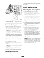
Belt Maintenance . . . . . . . . . . . . . . . . . . . . . . . . . . . . . . . . . . . . . . . 46
Inspecting the Belts . . . . . . . . . . . . . . . . . . . . . . . . . . . 46
R e placing the Mo w er Belt . . . . . . . . . . . . . . . . . . 46
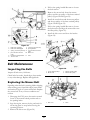
R e placing the Dri v e Belts . . . . . . . . . . . . . . . . . . . 47
Adjusting the Dri v e Belts . . . . . . . . . . . . . . . . . . . 47
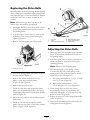
R e placing the Pump Dri v e
Belt . . . . . . . . . . . . . . . . . . . . . . . . . . . . . . . . . . . 48
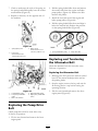
R e placing and T ensioning the
Alter nator Belt . . . . . . . . . . . . . . . . . . . 48
Controls System Maintenance . . . . . . . . . . . . . . . . . . . . 49
Adjusting the Control Handle
Neutral P osition . . . . . . . . . . . . . . . . 49
Hy draulic System Maintenance . . . . . . . . . . . . . . . . . . 50
Ser vicing the Hy draulic
System . . . . . . . . . . . . . . . . . . . . . . . . . . . . . . . 50
Setting the Hy draulic Pump
Neutral P osition . . . . . . . . . . . . . . . . 53
Mo w er Dec k Maintenance . . . . . . . . . . . . . . . . . . . . . . . . . 54
Lev eling the Mo w er at T hree
P ositions . . . . . . . . . . . . . . . . . . . . . . . . . . . 54
Ser vicing the Cutting Blades . . . . . . . . . . . . . . . 57
R e placing the Grass Deflector . . . . . . . . . . . . 60
Cleaning . . . . . . . . . . . . . . . . . . . . . . . . . . . . . . . . . . . . . . . . . . . . . . . . . . . . 60
Cleaning Under the Mo w er . . . . . . . . . . . . . . . . 60
W aste Disposal . . . . . . . . . . . . . . . . . . . . . . . . . . . . . . . . . . 61
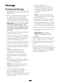
Storag e . . . . . . . . . . . . . . . . . . . . . . . . . . . . . . . . . . . . . . . . . . . . . . . . . . . . . . . . . . . . . . 62
Cleaning and Storag e . . . . . . . . . . . . . . . . . . . . . . . . . 62
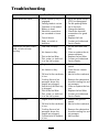
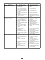
T roubleshooting . . . . . . . . . . . . . . . . . . . . . . . . . . . . . . . . . . . . . . . . . . . . . . . . 63
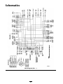
Sc hematics . . . . . . . . . . . . . . . . . . . . . . . . . . . . . . . . . . . . . . . . . . . . . . . . . . . . . . . . 66
3

Safety
Improper use or maintenance b y the operator or
o wner can result in injur y . T o reduce the potential
for injur y , comply with these safety instr uctions
and alw a ys pa y attention to the safety aler t symbol,
whic h means CA UTION , W ARNING , or
D ANGER -“personal safety instr uction." F ailure
to comply with the instr uction ma y result in
personal injur y or death.
T his product is capable of amputating hands and
feet and thro wing objects . Alw a ys follo w all safety
instr uctions to a v oid serious injur y or death.
T his product is designed for cutting and recycling
g rass or , when equipped with a g rass bag g er , for
catc hing cut g rass . Any use for pur poses other
than these could pro v e dang erous to user and
b ystanders .
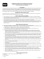
Safe Operating Practices
T he follo wing instr uctions are from ANSI
standard B71.4-2004.
Training
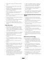
• R ead the Operator’ s Man ual and other training
material. If the operator(s) or mec hanic(s) can
not read English it is the o wner’ s responsibility
to explain this material to them.
• Become familiar with the safe operation of the
equipment, operator controls , and safety signs .
• All operators and mec hanics should be trained.
T he o wner is responsible for training the users .
• Nev er let c hildren or untrained people operate
or ser vice the equipment. Local regulations
ma y restrict the ag e of the operator .
• T he o wner/user can prev ent and is responsible
for accidents or injuries occur ring to himself
or herself , other people or proper ty .
Preparation
• Ev aluate the ter rain to deter mine what
accessories and attac hments are needed to
properly and safely perfor m the job . Only use
accessories and attac hments appro v ed b y the
man ufacturer .
• W ear appropriate clothing including hard hat,
safety glasses and hearing protection. Long
hair , loose clothing or jew elr y ma y g et tangled
in mo ving par ts .
• Inspect the area where the equipment is to be
used and remo v e all objects suc h as roc ks , to ys
and wire whic h can be thro wn b y the mac hine .
• Use extra care when handling diesel and other
fuels . T hey are flammable and v apors are
explosi v e .
– Use only an appro v ed container
– Nev er refuel or drain the mac hine indoors .
– Nev er remo v e g as cap or add fuel with
engine r unning . Allo w engine to cool
before refueling . Do not smok e .
• Chec k that operator’ s presence controls ,
safety switc hes and shields are attac hed and
functioning properly . Do not operate unless
they are functioning properly .
Operation
• Nev er r un an engine in an enclosed area.
• Only operate in g ood light, k ee ping a w a y from
holes and hidden hazards .
• Be sure all dri v es are in neutral and parking
brak e is eng ag ed before star ting engine . Star t
the engine only from the operator’ s position.
Use seat belts .
• Nev er raise mo w er with the blades r unning .
• Nev er operate without the PTO shield, or
other guards securely in place . Be sure all
interloc ks are attac hed, adjusted properly , and
functioning properly .
• Nev er operate with the disc harg e deflector
raised, remo v ed or altered, unless using a g rass
catc her .
• Do not c hang e the engine g o v er nor setting or
o v erspeed the engine .
• Stop on lev el g round, lo w er implements ,
diseng ag e dri v es , eng ag e parking brak e , shut
off engine before lea ving the operator’ s
position for any reason including emptying the
catc hers or unclog ging the c hute .
• Stop equipment and inspect blades after
striking objects or if an abnor mal vibration
occurs . Mak e necessar y re pairs before
resuming operations .
4

• K ee p hands and feet a w a y from the cutting
units .
• Nev er car r y passeng ers and k ee p pets and
b ystanders a w a y .
• Be aler t, slo w do wn and use caution when
making tur ns . Look behind and to the side
before c hanging directions .
• Slo w do wn and use caution when crossing
roads and sidew alks . Stop blades if not
mo wing .
• Be a w are of the mo w er disc harg e direction and
do not point it at any one .
• Do not operate the mo w er under the influence
of alcohol or dr ugs .
• Use extreme care when loading or unloading
the mac hine into a trailer or tr uc k.
• Use care when approac hing blind cor ners ,
shr ubs , trees , or other objects that ma y obscure
vision.
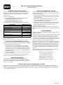
Slope Operation
• Do not mo w slopes g reater than 15 deg rees .
• Do not mo w near drop-offs , ditc hes , stee p
banks or w ater . W heels dropping o v er edg es
can cause rollo v ers , whic h ma y result in serious
injur y , death or dro wning .
• Do not mo w slopes when g rass is w et. Slipper y
conditions reduce traction and could cause
sliding and loss of control.
• Do not mak e sudden tur ns or rapid speed
c hang es .
• Use a w alk behind mo w er and/or a hand
trimmer near drop-offs , ditc hes , stee p banks
or w ater .
• R educe speed and use extreme caution on
slopes .
• R emo v e or mark obstacles suc h as roc ks , tree
limbs , etc . from the mo wing area. T all g rass
can hide obstacles .
• W atc h for ditc hes , holes , roc ks , dips , and rises
that c hang e the operating angle , as rough
ter rain could o v er tur n the mac hine .
• A v oid sudden star ts when mo wing uphill
because the mo w er ma y tip bac kw ards .
• Be a w are that loss of traction ma y occur g oing
do wnhill. W eight transfer to the front wheels
ma y cause dri v e wheels to slip and cause loss
of braking and steering .
• Alw a ys a v oid sudden star ting or stopping on
a slope . If tires lose traction, diseng ag e the
blades and proceed slo wly off the slope .
• F ollo w the man ufacturer’ s recommendations
for wheel w eights or counterw eights to
impro v e stability .
• Use extreme care with g rass catc hers or other
attac hments . T hese can c hang e the stability of
the mac hine and cause loss of control.
Using the Rollover Protection System
(ROPS)
• K ee p the roll bar in the raised and loc k ed
position and use the seat belt when operating
the mac hine .
• Be cer tain that the seat belt can be released
quic kly in the ev ent of an emerg ency .
• Be a w are there is no rollo v er protection when
the roll bar is do wn.
• Chec k the area to be mo w ed and nev er fold
the R OPS in areas where there are slopes , drop
offs or w ater .
• Lo w er the rollbar only when absolutely
necessar y . Do not w ear the seat belt with the
roll bar folded do wn.
• Chec k carefully for o v erhead clearances (i.e .
branc hes , doorw a ys , electrical wires) before
dri ving under any objects and do not contact
them.
Maintenance and storage
• Diseng ag e dri v es , lo w er implement, set
parking brak e , stop engine and remo v e k ey
or disconnect spark plug wire . W ait for all
mo v ement to stop before adjusting, cleaning
or re pairing .
• Clean g rass and debris from cutting units ,
dri v es , m ufflers , and engine to help prev ent
fires . Clean up oil or fuel spillag e .
• Let engine cool before storing and do not store
near flame .
• Shut off fuel while storing or transpor ting . Do
not store fuel near flames or drain indoors .
• P ark mac hine on lev el g round. Nev er allo w
untrained personnel to ser vice mac hine .
• Use jac k stands to suppor t components when
required.
5

• Carefully release pressure from components
with stored energ y .
• Disconnect batter y or remo v e spark plug wire
before making any re pairs . Disconnect the
neg ati v e ter minal first and the positi v e last.
R econnect positi v e first and neg ati v e last.
• Use care when c hec king blades . W rap the
blade(s) or w ear glo v es , and use caution when
ser vicing them. Only re place blades . Nev er
straighten or w eld them.
• K ee p hands and feet a w a y from mo ving par ts .
If possible , do not mak e adjustments with the
engine r unning .
• Charg e batteries in an open w ell v entilated
area, a w a y from spark and flames . Unplug
c harg er before connecting or disconnecting
from batter y . W ear protecti v e clothing and use
insulated tools .
• K ee p all par ts in g ood w orking condition and
all hardw are tightened. R e place all w or n or
damag ed decals .
• Use only T oro appro v ed attac hments .
W ar ranty ma y be v oided if used with
unappro v ed attac hments .
6

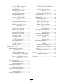
Slope Chart
7

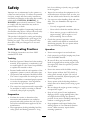
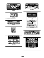
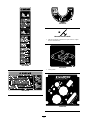
Safety and Instructional
Decals
Safety decals and instr uctions are easily visible to the operator and are located near any
area of potential dang er . R e place any decal that is damag ed or lost.
1-403005
1-523552
1-643253
54-9220
58-6520
1. Grease
66-1340
65-2690
8

68-8340
98-4387
1. Warning—wear hearing protection.
98-5954
103-1636
103-3276
103-5881
104-2449
104-7759
105-7798
9

106-7492
106-9989
107-1613
110-2067
10

110-2068
1. Read the Operator’s Manual .
107-1857
107-1860
107-1861
107-1864
11

107-2102
107-2112
107-2114
Manufacturer’s Mark
1. Indicates the blade is identied as a part from the original
machine manufacturer.
107-7673
1. Cutting blade
110-5733
12

107-7705
107-9863
107-9864
1. Read the Operator’s Manual .
13

107-9866
1. Fast
2. Slow 3. Neutral
4. Reverse
14

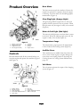
Product Overview
Figure 3
1. Motion control lever 5. Controls
2. Parking brake lever 6. Seat belt
3. Height-of-cut lever 7. Roll bar
4. Fuel cap (both sides)
8. Engine screen
Controls
Become familiar with all the controls before y ou
star t the engine and operate the mac hine ( Figure 3
and Figure 4 ).
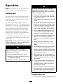
Figure 4
1. Ignition switch 6. Fuel cap
2. Throttle control 7. Volt meter
3. Glow plug light
8. Engine Temperature gauge
4. Power take off (PTO) Switch
9. Water in fuel light
5. Hour meter
Hour Meter
T he hour meter records the n umber of hours the
engine has operated. It operates when the engine
is r unning . Use these times for sc heduling regular
maintenance ( Figure 4 ).
Glow Plug Light (Orange Light)
T he glo w plug indicator light tur ns on when the
ignition switc h is tur ned to the on position. W hen
the light tur ns off , the engine is ready to be star ted
( Figure 4 ).
Water in Fuel Light (Red Light)
T he w ater in fuel light tur ns on when there is w ater
in the fuel. W hen the indicator light tur ns off , the
engine is ready to be star ted ( Figure 4 ).
Temperature Gauge
T he temperature g aug e registers the temperature
of the coolant in the cooling system ( Figure 4 ).
Audible Alarm
T his mac hine has an audible alar m that aler ts the
user to tur n off the engine or engine damag e can
occur from o v er heating . R efer to Ser vicing the
Cooling System in Cooling System Maintenance ,
pag e 44 .
Volt Meter
T he v olt meter registers the output of the c harging
system ( Figure 4 ).
15

Operation
Note: Deter mine the left and right sides of the
mac hine from the nor mal operating position.
Adding Fuel
T he engine r uns on clean, fresh diesel fuel with
a minim um octane rating of 40. Purc hase fuel
in quantities that can be used within 30 da ys to
ensure fuel freshness .
Use summer g rade diesel fuel (No . 2-D) at
temperatures abo v e 20° F (-7° C) and winter g rade
diesel fuel (No . 1-D or No . 1-D/2-D blend) belo w
20° F (-7° C). Use of winter g rade diesel fuel at
lo w er temperatures pro vides lo w er flash point
and pour point c haracteristics , therefore easing
star tability and lessening c hances of c hemical
se paration of the fuel due to lo w er temperatures
(w ax appearance , whic h ma y plug filters).
Use of summer g rade diesel fuel abo v e 20° F (-7°
C) will contribute to w ard long er life of the pump
components .
Important: Do not use k er osene or gasoline
instead of diesel fuel. F ailur e to obser v e this
caution will dama ge the engine.
Fuel is har mful or f atal if s w allo w ed.
Long-ter m exposur e to v apor s can cause
serious injur y and illness.
• A v oid pr olonged br eathing of v apor s.
• K eep f ace a w ay fr om nozzle and gas tank
or conditioner opening .
• K eep gas a w ay fr om ey es and skin.
In cer tain conditions, fuel is extr emel y
flamma ble and highl y explosi v e. A fir e or
explosion fr om fuel can bur n y ou and other s
and can dama ge pr oper ty .
• Fill the fuel tank outdoor s, in an open
ar ea, when the engine is cold. W ipe up
an y fuel that spills.
• Nev er fill the fuel tank inside an enclosed
trailer .
• Do not fill the fuel tank completel y full.
Add fuel to the fuel tank until the lev el is
1/4 to 1/2 inch (6 to 13 mm) belo w the
bottom of the filler neck. T his empty
space in the tank allo ws fuel to expand.
• Nev er smok e when handling fuel, and
stay a w ay fr om an open flame or wher e
fuel fumes may be ignited by a spar k.
• Stor e fuel in an appr o v ed container and
k eep it out of the r each of childr en.
Nev er buy mor e than a 30-day suppl y of
fuel.
• Al w ays place fuel container s on the
g r ound a w ay fr om y our v ehicle bef or e
filling .
• Do not fill fuel container s inside a v ehicle
or on a tr uck or trailer bed because
interior car pets or plastic tr uck bed liner s
may insulate the container and slo w the
loss of an y static charge.
• W hen practical, r emo v e gas-po w er ed
equipment fr om the tr uck or trailer and
r efuel the equipment with its wheels on
the g r ound.
• If this is not possible, then r efuel such
equipment on a tr uck or trailer fr om a
por ta ble container , rather than fr om a
fuel dispenser nozzle.
• If a fuel dispenser nozzle must be used,
k eep the nozzle in contact with the rim
of the fuel tank or container opening at
all times until fueling is complete.
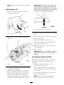
Filling the Fuel Tank
1. Shut the engine off and set the parking brak e .
16

2. Clean around eac h fuel tank cap and remo v e
the cap . Add fuel to both fuel tanks , until the
lev el is 1/4 to 1/2 inc h (6 to 13 mm) belo w
the bottom of the filler nec k. T his space in the
tank allo ws the fuel to expand. Do not fill the
fuel tanks completely full.
3. Install fuel tank caps securely . Wipe up any
fuel that ma y ha v e spilled.
4. If possible , fill the fuel tank after eac h use . T his
will minimize possible buildup of condensation
inside the fuel tank.
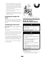
Checking the Engine Oil
Level
Before y ou star t the engine and use the mac hine ,
c hec k the oil lev el in the engine crankcase; refer to
Chec king the Oil Lev el in Engine Maintenance ,
pag e 35
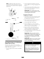
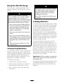
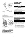
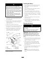
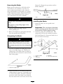
Switching the Fuel Tanks
Important: Do not r un the machine out of
fuel.
T he fuel selector v alv e is located behind the left
side of the seat.
T he unit has tw o fuel tanks . One tank is on the left
side and one on the right side . Eac h tank connects
to the fuel selector v alv e . F rom there a common
fuel line leads to the engine ( Figure 5 ).
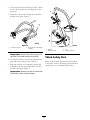
T o use the left side fuel tank rotate the fuel selector
v alv e to the LH position, lefthand location. T o use
the right side fuel tank rotate the fuel selector v alv e
to the RH position, righthand location ( Figure 5 )
Close the fuel selector v alv e before transpor ting
or storing mac hine .
Figure 5
1. Left side fuel tank 2. Fuel selector valve
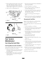
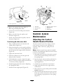
Using the Rollover
Protection System (ROPS)
T o a v oid injur y or death fr om r ollo v er : k eep
the r oll bar in the raised lock ed position and
use the seat belt.
Ensur e that the r ear par t of the seat is
secur ed with the seat latch.
T her e is no r ollo v er pr otection when the r oll
bar is in the do wn position.
• Lo w er the r oll bar onl y when a bsolutel y
necessar y .
• Do not w ear the seat belt when the r oll
bar is in the do wn position.
• Dri v e slo wl y and car efull y .
• R aise the r oll bar as soon as clearance
per mits.
• Check car efull y f or o v erhead clearances
(i.e. branches, doorw ays, electrical wir es)
bef or e dri ving under an y objects and do
not contact them.
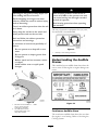
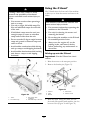
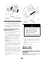
Important: Lo w er the r oll bar onl y when
a bsolutel y necessar y .
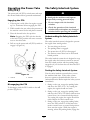
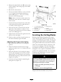
1. T o lo w er the roll bar , remo v e the hair pin cotter
pins and remo v e the tw o pins ( Figure 7 ).
17

2. Lo w er the roll bar to the do wn position. T here
are tw o do wn positions . See Figure 6 for the
positions .
3. Install the tw o pins and secure them with the
hair pin cotter pins ( Figure 7 ).
Figure 6
1. Full down position 2. Down position with bagger
installed
Important: Ensur e that the r ear par t of
the seat is secur ed with the seat latch.
4. T o raise the roll bar , remo v e the hair pin cotter
pins and remo v e the tw o pins ( Figure 7 ).
5. Raise the roll bar to the upright position and
install the tw o pins and secure them with the
hair pin cotter pins ( Figure 7 ).
Important: Al w ays use the seat belt with
the r oll bar in the raised position.
Figure 7
1. Roll bar
3. Pin
2. Raised position
4. Hairpin cotter pin
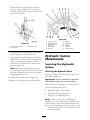
Think Safety First
Please read all safety instr uctions and symbols
in the safety section. Kno wing this infor mation
could help y ou or b ystanders a v oid injur y .
18

Operating on w et g rass or steep slopes can
cause sliding and loss of contr ol.
W heels dr opping o v er edges can cause
r ollo v er s, which may r esult in serious injur y ,
death or dr o wning .
T her e is no r ollo v er pr otection when the r oll
bar is do wn.
Al w ays k eep the r oll bar in the raised and
lock ed position and use the seat belt.
R ead and f ollo w the r ollo v er pr otection
instr uctions and w ar nings.
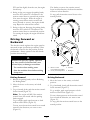
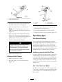
T o a v oid loss of contr ol and possibility of
r ollo v er :
• Do not operate near dr op-of fs or near
w ater .
• Do not operate on slopes g r eater than
15 deg r ees.
• R educe speed and use extr eme caution
on slopes.
• A v oid sudden tur ns or rapid speed
changes.
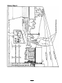
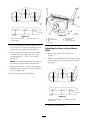
Figure 8
1. Safe Zone-use the Z Master
here on slopes less than
15 degrees or at areas.
3. Water
2. Use walk behind mower
and/or hand trimmer near
drop-offs and water.
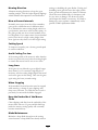
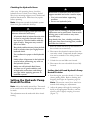
T his machine pr oduces sound lev els in
ex cess of 85 dB A at the operator s ear and
can cause hearing loss thr ough extended
periods of exposur e.
W ear hearing pr otection when operating
this machine.
T he use of protecti v e equipment for eyes , ears ,
feet and head is recommended.
Figure 9
1. Warning— wear hearing protection
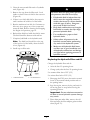
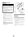
Understanding the Audible
Alarms
T his mac hine has an audible alar m that aler ts the
user to tur n off the engine or engine damag e can
occur .
Figure 10
Continuous Audible Alarm
T he contin uous audible alar m aler ts the user that
the engine is o v er heating . R efer to Ser vicing the
Cooling System.
19

Pulsing Audible Alarm
T he pulsing audible alar m aler ts the user to lo w oil
pressure or the alter nator is not c harging . R efer to
Chec king the Engine Oil and c hec k the alter nator
belt.
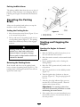
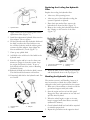
Operating the Parking
Brake
Alw a ys set the parking brak e when y ou stop the
mac hine or lea v e it unattended.
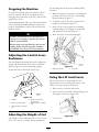
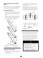
Setting the Parking Brake
1. Mo v e the motion control lev ers ( Figure 15 ) out
to the neutral loc k position.
2. Pull up and bac k on the parking brak e lev er to
set the parking brak e ( Figure 11 ). T he parking
brak e lev er should sta y fir mly in the eng ag ed
position.
P ar king brak e may not hold machine
par k ed on a slope and could cause
per sonal injur y or pr oper ty dama ge.
Do not par k on slopes unless wheels ar e
chock ed or block ed
Releasing the Parking Brake
Push forw ard and do wn on the parking brak e
lev er to release the parking brak e ( Figure 11 ). T he
parking brak e is diseng ag ed and the lev er will rest
ag ainst the brak e stop .
Figure 11
1. Parking brake-ON 3. Brake Stop
2. Parking brake-OFF
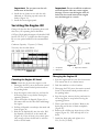
Starting and Stopping the
Engine
Starting the Engine in Normal
Weather
1. Raise the R OPS up and loc k into place , sit on
the seat and fasten the seat belt.
2. Mo v e the motion controls to the neutral loc k ed
position.
3. Set the parking brak e; refer to Setting the
P arking Brak e .
4. Mo v e the PTO (po w er tak e off) switc h to the
off position.
5. Mo v e the throttle lev er to the middle position
( Figure 13 ).
6. T ur n the ignition k ey cloc kwise to the r un
position ( Figure 12 ). T he glo w plug light will
tur n on.
7. After the glo w plug indicator light g oes out,
tur n the k ey to the star t position. when the
engines star ts release the k ey .
Important: Use star ting cy cles of no
mor e than 30 seconds per min ute to a v oid
o v erheating the star ter motor .
8. If the engine does not star t immediately , mo v e
the throttle control to fast and tur n the k ey to
the star t position.
20
Page is loading ...
Page is loading ...
Page is loading ...
Page is loading ...
Page is loading ...
Page is loading ...
Page is loading ...
Page is loading ...
Page is loading ...
Page is loading ...
Page is loading ...
Page is loading ...
Page is loading ...
Page is loading ...
Page is loading ...
Page is loading ...
Page is loading ...
Page is loading ...
Page is loading ...
Page is loading ...
Page is loading ...
Page is loading ...
Page is loading ...
Page is loading ...
Page is loading ...
Page is loading ...
Page is loading ...
Page is loading ...
Page is loading ...
Page is loading ...
Page is loading ...
Page is loading ...
Page is loading ...
Page is loading ...
Page is loading ...
Page is loading ...
Page is loading ...
Page is loading ...
Page is loading ...
Page is loading ...
Page is loading ...
Page is loading ...
Page is loading ...
Page is loading ...
Page is loading ...
Page is loading ...
Page is loading ...
Page is loading ...
-
 1
1
-
 2
2
-
 3
3
-
 4
4
-
 5
5
-
 6
6
-
 7
7
-
 8
8
-
 9
9
-
 10
10
-
 11
11
-
 12
12
-
 13
13
-
 14
14
-
 15
15
-
 16
16
-
 17
17
-
 18
18
-
 19
19
-
 20
20
-
 21
21
-
 22
22
-
 23
23
-
 24
24
-
 25
25
-
 26
26
-
 27
27
-
 28
28
-
 29
29
-
 30
30
-
 31
31
-
 32
32
-
 33
33
-
 34
34
-
 35
35
-
 36
36
-
 37
37
-
 38
38
-
 39
39
-
 40
40
-
 41
41
-
 42
42
-
 43
43
-
 44
44
-
 45
45
-
 46
46
-
 47
47
-
 48
48
-
 49
49
-
 50
50
-
 51
51
-
 52
52
-
 53
53
-
 54
54
-
 55
55
-
 56
56
-
 57
57
-
 58
58
-
 59
59
-
 60
60
-
 61
61
-
 62
62
-
 63
63
-
 64
64
-
 65
65
-
 66
66
-
 67
67
-
 68
68


Toro Z597-D Z Master, With 60in TURBO FORCE Side Discharge Mower User manual
- Category
- Lawnmowers
- Type
- User manual
- This manual is also suitable for
Ask a question and I''ll find the answer in the document
Finding information in a document is now easier with AI
Related papers
-
Toro Z Master Professional 7000 Series Riding Mower, With 72in TURBO FORCE Side Discharge Mower User manual
-
Toro Z590-D Z Master, With 60in TURBO FORCE Side Discharge Mower User manual
-
Toro Z580-D Z Master, With 52in TURBO FORCE Side Discharge Mower User manual
-
Toro Z580-D Z Master, With 132cm TURBO FORCE Side Discharge Mower User manual
-
-
Toro Z Master Professional 7000 Series Riding Mower, With 72in TURBO FORCE Side Discharge Mower User manual
-
-
Toro Z597-D Z Master, With 72in TURBO FORCE Side Discharge Mower User manual
-
-
Other documents
-
 Great Dane GSRKA1934S User manual
-
 Wooster 0BR0370180 Operating instructions
-
Simplicity 080020-00 User manual
-
-
Kohler 300REZXD Operating instructions
-
-
-
Graco 3A0733H User manual
-
CyClone HC40236 User manual
-
Ares 18051 User manual

