Page is loading ...

1
http://www.TYAN.com
Transport GS14 / / / B5121G14S2
Revision 1.02
Copyright © TYAN Computer Corporation, 2006. All rights reserved. No part of this
manual may be reproduced or translated without prior written consent from TYAN
Computer Corp.
All registered and unregistered trademarks and company names contained in this
manual are property of their respective owners including, but not limited to the
following:
TYAN and Transport GS14 (B5121G14S2) are trademarks of TYAN Computer
Corporation.
Intel and combinations thereof are trademarks of Intel Corporation.
Phoenix BIOS is a trademark of Phoenix Technology.
Microsoft and Windows are trademarks of Microsoft Corporation.
IBM, PC, AT, PS/2 are trademarks of IBM Corporation.
ATI, ATI RAGE is a trademark of ATI Technologies Incorporated.
Winbond is a trademark of Winbond Electronics Corporation.
Information contained in this document is furnished by TYAN Computer Corporation
and has been reviewed for accuracy and reliability prior to printing. TYAN assumes no
liability whatsoever, and disclaims any express or implied warranty, relating to sale
and/or use of TYAN products including liability or warranties relating to fitness for a
particular purpose or merchantability. TYAN retains the right to make changes to
product descriptions and/or specifications at any time, without notice. In no event will
TYAN be held liable for any direct or indirect, incidental or consequential damage, loss
of use, loss of data or other malady resulting from errors or inaccuracies of information
contained in this document.
WARNING: This product should be serviced only by qualified service engineers. Do not
remove the chassis cover or attempt to service this product unless you are qualified to do
so. Once the chassis cover is removed there is a risk of electric shock which could lead
to serious injury or death.

2
http://www.TYAN.com
1 Table of Contents
Before You Begin............................................................................ 4
Safety Precautions ........................................................................... 4
Chapter 1 Introduction............................................................................................ 5
1.1 Unpacking........................................................................................ 5
1.2 Specifications .................................................................................. 8
1.3 System View.................................................................................... 9
Front View....................................................................................... 9
Rear View...................................................................................... 10
System Assembly Flowchart......................................................... 12
Chapter 2 Hardware Installation.......................................................................... 15
2.1 System Assembly .......................................................................... 13
Safety Considerations.................................................................... 13
Opening the Cover......................................................................... 13
Installing the CPU ......................................................................... 13
Installing System Memory............................................................. 17
Installing a Hard Disk Drive.......................................................... 19
2.2 Adding a CD Drive........................................................................ 22
With a Ultra ATA/100 Hard Disk Drive Installed......................... 22
Without a Ultra ATA/100 Hard Disk Drive Installed.................... 24
2.3 Rack Mounting (Option)................................................................ 24
Cabinet Slides and Ears................................................................. 25
Cabinet into the Rack .................................................................... 27
Locking Tab................................................................................... 27
2.4 Setting Up the System ................................................................... 28
Placing the System......................................................................... 28
Making the Connection ................................................................. 28
For 32-bit OS................................................................................. 31
For 64-bit OS................................................................................. 32
Chapter 3 Software Installation............................................................................ 33
3.1 Installation Instructions for Windows............................................ 33
Windows Installation Notes........................................................... 33
Chipset Driver ............................................................................... 33
VGA Driver................................................................................... 34
Intel Matrix Storage Manager........................................................ 34

3
http://www.TYAN.com
Intel 82562GT NIC (Network Interface Card) Driver................... 34
Broadcom 5721 LAN Driver......................................................... 35
LCD Driver................................................................................................35
3.2 Installation Instructions for Linux (RedHat/Fedora/SuSE)............ 36
Linux Installation Notes................................................................. 36
VGA Driver................................................................................... 36
Intel 82562GT NIC (Network Interface Card) Driver
Broadcom 5721 Driver.................................................................. 37
LCD Driver.................................................................................... 37
3.3 Installation Instructions for FreeBSD 5.4...................................... 37
Intel 82562GT NIC (Network Interface Card) Driver................... 37
Broadcom 5721 Driver.................................................................. 37
Chapter 4 BIOS Setup............................................................................................ 39
4.1 BIOS Setup Program ..................................................................... 39
Starting BIOS Setup ......................................................................39
Main Menu ....................................................................................40
Advanced Menu............................................................................. 41
Security Menu................................................................................ 42
Power Menu................................................................................... 43
Monitor Menu................................................................................ 43
Boot Menu..................................................................................... 44
Exit Menu...................................................................................... 44
4.2 Resetting BIOS Setup.................................................................... 45
Chapter 5 Expanding the System..........................................................................47
5.1 Opening the Cover......................................................................... 47
5.2 Installing an Expansion Card......................................................... 48
5.3 Adding a Secondary Hard Disk Drive........................................... 49
Chapter 6 System Parts Replacement................................................................... 53
6.1 Opening the Cover......................................................................... 53
6.2 Removing the Front Bezel............................................................. 54
6.3 Replacing the Button Board........................................................... 55
6.4 Replacing the Fan.......................................................................... 56
6.5 Replacing the USB Board.............................................................. 57
6.6 Replacing the LCD Module........................................................... 58
6.7 Replacing the Power Supply.......................................................... 59
6.8 Replacing the Motherboard ........................................................... 60
Chapter 7 Appendix................................................................................................ 61
Caution Texts Concerning Lithium Batteries......................................... 61
Technical Support................................................................................... 62

4
http://www.TYAN.com
Before You Begin
This manual provides hardware-related information of the system for administrators
who use it to develop and host web sites. The administrators should be familiar with
operating systems and web browsers.
Depending on the model purchased, your system may come with pre-installed software.
For software information, refer to the documentation accompanying the software.
Safety Precautions
z Use the type of power indicated on the marking label.
z Ensure that electrical circuits are not overloaded; consider the nameplate ratings of
all the connected equipment and ensure that you have over current protection.
z Do not disable the power cord ground feature. This equipment was designed to
connect to a grounded (earthed) power outlet. The grounding plug is an important
safety feature.
z Ensure that the power outlet is located or installed near the equipment and is easily
accessible.
z Do not allow anything to rest on the power cord. Do not locate this product where
persons will walk on the cord.
z Ensure the ambient temperature around the equipment (which may be higher than
the room temperature) is within the limits specified in section 1.2.
z Slots and openings in the cabinet are provided for ventilation. Do not block or
cover these openings. Do not push objects of any kind into cabinet slots or
openings.

5
http://www.TYAN.com
1 Introduction
Congratulations on purchasing the system. This chapter introduces the features and
functions of the product.
1.1 Unpacking
After unpacking the shipping carton, you should find these standard items:
1× B5121G14S2 case kit
1× motherboard (pre-installed)
1× LCD module (pre-installed)
1× button board (pre-installed)
1× USB board (pre-installed)
1× fan assembly 40*28 mm (pre-installed)
2× fan assembly 40*56 mm (pre-installed)
1× power supply 1U ATX 300 W (pre-installed)
1× riser board 32-bit / 33 MHz (pre-installed)
1× fan holder (pre-installed)

6
http://www.TYAN.com
And the following accessories:
1× pair of ear bracket
1× heatsink
1× primary serial ATA cable
1× secondary serial ATA cable
1× HDD power to pin-header cable
1× primary serial ATA power cable
1× secondary serial ATA power cable
1× IDE cable
1× power Y-cable
2× power cord (USA and Germany)
4× rubber feet
1× TYAN driver CD
1× B5121 User’s Manual
1× Rail Kit
Inspect all the items. If any item is damaged or missing, notify your dealer immediately.
Keep the shipping carton and packing materials in case you need to ship or store the
computer in the future.
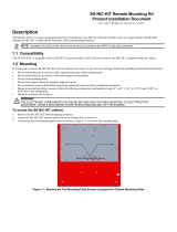
Note: The following items are included in the Rail Kit:
1) 1× Slide
2) 4 x Bracket Rail Kit

7
http://www.TYAN.com
3) 4 x Screw Kit
4) 1 x pair of Ear bracket (Please refer to the above picture for them)
5) 1 x pair of Handle Kit
6) 1 x Packing Kit (Including 1 x Box, 2 x Sponge, 1 x End cap )
7) 1 x Instruction Sheet

8
http://www.TYAN.com
1.2 Specifications
NOTE: Specifications are subject to change without notice.
Processor
• Single socket-T LGA775
• Intel
®
Pentium 4 Prescott 5xx/6xx or
Celeron D 3xx processor
• Supports 533/800 MHz FSB
Chipset
• Intel 915GV (NorthBridge)
• ICH6R (SouthBridge)
• SMC LPC47M172 Super I/O chip
• Winbond 83792 hardware monitor
Memory
• Four 240-pin DDR2 DIMM slots
• Single/dual-channel mode support
• Up to 4 GB of non-ECC DDR2
Expansion Slot
• One 32-bit / 33 MHz PCI v2.3 slot on riser
card
Integrated PCI Graphics
• 915GV embedded graphic controller
• Shared system memory 1 MB
(4/8/16/32/64/128 MB)
External I/O Ports (Rear)
• One 9-pin UART serial port
• One VGA port
• Two RJ-45 LAN connectors
• Two USB 2.0 ports
• One PS/2 keyboard/mouse connector
Front Panel Features
• LED Indicators
– Power
– Two LAN (Giga, 10/100M)
– HDD
• LCD interface
– 2 x 16 digits
– Connected via COM2
– Four direction buttons plus one “Select”
and one “Cancel” button
• Two USB 2.0 ports
NOS (Network O/S) Support
• Windows 2003 Server 64-bit and 32-bit
• Windows XP
• Linux RHEL ES 3.0
• Linux RHEL 4.0
• Fedora Core 3 / Core 4
Networking
• One 10/100 Ethernet LAN port from
ICH6R with Intel® 82562GT PHY
• One gigabit Ethernet LAN port (Broadcom
BCM5721)
• Supports PXE and WOL
Storage Capacity
• One IDE (Ultra ATA/100) HDD or two
SATA HDDs
• SATA HDDs support RAID0, RAID1
Integrated Hardware Monitoring
• CPU temperature and voltage monitoring
• Automatic fan speed control mode
• CPU and system fan speed monitoring
and control
• 5 x 3-pin header for system fans
• Monitor up to 6 processor VID bits
BIOS
• Phoenix BIOS on 8 MB Flash ROM
• ACPI 2.0 / APM 1.2
• SM BIOS 2.3.3 (backward-compatible with
DMI 2.0)
• UCR and LAN remote boot (PXE) support
• Power Management: S1 and S5-type
Environment
• Operating temperature:
5
0
C (41
0
F) to 35
0
C (95
0
F)
• Operating relative humidity:
0 % to 80 % non-condensing
• Operating altitude:
–50 ft to 10,000 ft
Cabinet Form Factor
• Sub-1U rack-mountable chassis
• Dimension:
W16.7 x D15.3 x H1.7 inch
W424 x D387.7 x H43.5 mm
Power Supply
• ATX 12 V 1U 300 W with PSU
Regulatory
• FCC Class A
• CE (Declaration of Conformity)
• UL/cUL
• TUV

9
http://www.TYAN.com
1.3 System View
Front View
Ref Component Description
n
Power Button
Turns the power on and off (soft-off).
o
Power Indicator
Glows green when the power is on.
p
LAN1 Indicator
Indicates a network connection on LAN1 (internal connection).
q
LAN2 Indicator
Indicates a network connection on LAN2 (external connection).
r
Hard Disk Drive
Indicator
Indicates activity on the hard disk drive.
s
USB Ports
Each of the two ports connects a USB device.
t
LCD Screen
Displays messages and values entered.
u
Control Buttons
Allow you to enter network configuration information, reboot the system,
and power down the system.

10
http://www.TYAN.com
Rear View
Ref Component Description
n
Ventilation Openings
Maintain proper operating temperature. Do not cover or block the
openings.
o
Power Connector
Connects the power cord.
p
Power Switch
Turns the main power of the system on and off.
q
PS/2 Keyboard/
Mouse Connector
Connects a PS/2 keyboard/mouse.
r
LAN2 Connector
Connects the LAN cable for external network connection.
s
LAN1 Connector
Connects the LAN cable for internal network connection.
t
Serial Port
Connects a serial device.
u
VGA Port
Connects an external CRT monitor.
v
USB Ports
Each of the two ports connects a USB device.
w
Expansion Slot
Allow you to install a PCI card.

11
http://www.TYAN.com
2 Hardware Installation
This chapter, which is divided into two sections, provides instructions on the hardware
installation of the system. System Assembly section illustrates how to assemble each
component of the system. Rack Mounting section describes the procedures for
mounting the system into the rack. You can use the system assembly flowchart and the
chart next to determine the proper sequence for removing or installing components to
the server.
System Assembly
Rack Mounting
Cabinet Cover
CPU and Heatsink
Hard Disk Drive
Cabinet
Rails and Ears
Cabinet into the Rack
Locking Tab
DIMM
Start

12
http://www.TYAN.com
System Assembly Flowchart
The following flowchart shows the basic procedures of system assembly:
FINISH
START
INSTALL
SYSTEM MEMORY
REMOVE CABINET COVER
INSTALL
CPU AND HEATSINK
INSTALL
HARD DISK DRIVE
CO
NNE
C
T H
A
RD DI
S
K
DRIVE CABLE
AND POWER CORD
CHECK IF ALL PARTS
A
RE PROPERLY CONNECTED
REPLACE
CABINET COVER

13
http://www.TYAN.com
2.1 System Assembly
When installing a device, be sure to read the instructions accompanying the device
together with the relevant section in this chapter.
Safety Considerations
z Static electricity can destroy electronic devices. Whenever you handle an option
outside of its protective packaging, first discharge any static electricity from your
body by touching a protective grounding device or unpainted metal on the rear
panel of the system before unplugging the power cord.
z Before you install any option, turn all power switches off. Unplug all power cords
from the system and all peripherals. Leaving the power on can cause serious
damage to your system.
z If the system is mounted on an equipment rack, remove the system from the rack
and take it to a service area. Do not attempt to disassemble the system while it is
still in the equipment rack.
Opening the Cover
1. Remove two screws from the back of the system. Pull the cover backward to detach
it.
2. To replace the cover, slide the cover forward and replace the two screws.
Installing the CPU
Your system supports socket-T LGA775 Intel Pentium 4 processor.
1. Remove the cabinet cover (see previous section).

14
http://www.TYAN.com
2. Find the socket-T on the motherboard.
3. Remove the black plastic protective cover on top of the socket-T (keep this for
future use in case you will need it).

15
http://www.TYAN.com
4. Lift the load lever up to the vertical position, then open the load plate.
5. Align the CPU so its Pin 1 corner (beveled corner) is at the Pin 1 corner of the
socket-T. Then insert the CPU's pins into the corresponding holes in the socket.
CAUTION: The CPU fits only in one correct orientation. Improper insertion of the CPU into
the socket may bend the pins on the socket-T and cause damage to the motherboard.
6. Apply some thermal grease on top of the CPU to aid in heat dissipation.

16
http://www.TYAN.com
7. Close the load plate, then carefully press the load lever downward to latch unto the
hook to secure it.
8. Place the heatsink assembly on top of the CPU and align the four points of the
heatsink socket. Secure with four screws following a diagonal sequence.
CAUTION: The heatsink must be installed, otherwise the CPU and/or motherboard will
overheat and be damaged.
9. Replace the cabinet cover.

17
http://www.TYAN.com
Installing System Memory
Your system has four 240-pin non-ECC DDR2 DIMM (Double Data Rate 2 Dual
In-line Memory Module) sockets to support a maximum of 4 GB.
Dual Channel Mode, instead of the default Single Channel Mode, can be enabled to
allow you to maximize the DIMMs performance. The installed DIMMs must meet the
following conditions:
z Matched DIMM configuration
(channel A comprises DIMM1 and DIMM2 while channel B comprises DIMM3 and
DIMM4) :
– same density and DRAM technology in each channel
(e.g., 128 MB, 256 MB, 512 MB, 1 GB, etc.)
– same DRAM bus width (e.g., ×8 or ×16) in each channel
– both DIMM should be either single-sided or double-sided
NOTE:
z The following conditions do not need to be met: same timing specifications and same
DDR2 speed.
z Memory interface speed will be set to the slowest speed of DIMM populated.
z Always install DIMMs with the same CAS latency. For optimum compatibility, it is
recommended that you obtain memory modules from the same vendor.
z DIMM installed into any one slot will function in Single Channel Mode.
z When the total DIMMs installed is over 4GB, only 4 GB may be available for system
use due to chipset limitation.
z Installing DIMMs other than the recommended configurations may cause memory
sizing error or system boot failure. Use any of the recommended configurations in the
next table.
Slots
Mode
DIMM1 DIMM2 DIMM3 DIMM4
Populated
Populated
Populated
Single Channel
Populated
Populated Populated
Populated Populated
Dual Channel
Populated Populated Populated Populated
Follow this procedure to install a DIMM:
1. Open the cabinet cover (see previous section).

18
http://www.TYAN.com
2. Locate the DIMM sockets.
3. To install the DIMM, make sure the retaining clips are in the unlocked position,
then align the DIMM’s notched end with the socket’s corresponding end and firmly
insert the DIMM into the socket. Finally push the retaining clips inwards to lock the
DIMM in place.
NOTE: The DIMM modules will fit in only one orientation. Do not touch the memory
module’s connectors. Handle only by the edges.
WARNING: DIMM modules become extremely hot during operation.
4. Replace the cabinet cover.

19
http://www.TYAN.com
Installing a Hard Disk Drive
NOTE: Make sure that the jumper setting of the hard disk drive is set to “Master.” (See the
hard disk drive’s documentation for information.)
WARNING: Please attach the hard bracket to the chassis to prevent enlarging the screw
holes even if you will not use hard disk drive
It is advised that you select a hard disk drive that meets the following specifications. A
hard disk drive that does not meet these specifications can cause reliability problems in
your system.
z Peak current draw: must not exceed 1.8 amperes maximum (at 5 volts) and 0.7
amperes maximum (at 12 volts)
z Rotational speed: 5400/7200 rpm
z Interface: Serial ATA
z Operating temperature: must be able to operate in environments up to 55 °C
z Operating humidity: 10 % to 90 % (non-condensing)
z IDE and SATA hard disk drives cannot be used in combination for RAID function
1. Remove the cabinet cover (see previous section).

20
http://www.TYAN.com
2. Locate the bracket for the primary hard disk drive, next to the power supply.
Remove the screw and slide the bracket off the metal tabs to detach it.
3. Secure the hard disk drive to the bracket with four bottom screws.
4. Fit the bracket with the hard disk drive back into place and secure with one screw.
5. Connect one end of the included Serial ATA data cable to the primary Serial ATA
connector (n) , connect the other end to the rear of hard disk drive 2 (o) (see
chapter 5 for adding a second hard disk drive), and insert the data cable into the wire
clip (p) . Connect the single end of the included power Y-cable to the power
/