Page is loading ...

This product is covered by one or more patents.
For more information visit www.gentexcorp.com/patents
UM-1057 REV-A
© 2019 Gentex Corporation. Ops-Core is a registered trademark or Gentex Corporation or its afliates.
BUMP HELMET
OPERATOR’S MANUAL


TABLE OF CONTENTS
Introduction
Helmet System Components
Sizing Guide
Retention System Operation
Pro Setup
Accessory Integration
Front Mount
Accessory Rail Connectors (ARCs)
Exterior Loop
Comms Headsets
Maintenance Schedule
Replacement Parts
Operator Notes
Warning & Warranty
4
5
6
7
8
10
11
12
13
14
15
16
17
18

HELMET VERSIONS
INTRODUCTION
This manual is specic to the Ops-Core FAST Bump Helmet Only.
PICATINNY ADAPTER (1)WING-LOC ADAPTER (1)
SIDE PAD TOP PAD TOP PAD REAR PAD
UNIVERSAL ADAPTER (1)
3
/
4
”
1
/
2
”
3
/
4
”
(2) SIDE PADS, (2) 1/2” TOP PADS, (2) 3/4” TOP PADS, (1) 1/2“ REAR PAD, (1) 3/4” REAR PAD
1
/
2
”
INCLUDES:
4

HELMET SYSTEM COMPONENTS
Fitband
Top EPP Pad
Front EPP Pad
Rear EPP Pad
Side EPP Pad
Side EPP Pad
Comfort Pad
Occ-Dial
Adjustment Knob
Head-Loc™ Retention System
Molded-In
Front Mount
Helmet
Shell
Exterior Loop
Ballistic
Screw
Accessory Rail
Connector (ARC)
Fitband
Top EPP Pad
Front EPP Pad
Rear EPP Pad
Side EPP Pad
Side EPP Pad
Comfort Pad
Occ-Dial
Adjustment Knob
Head-Loc™ Retention System
Molded-In
Front Mount
Helmet
Shell
Exterior Loop
Ballistic
Screw
Accessory Rail
Connector (ARC)
5

HELMET SIZING GUIDE
X-LARGE
FAST HELMET SIZE CHINSTRAP SIZE (
in
)
S/M
MEDIUM
M/L
L/XL
LARGE
27.5-30.5
26-29
24.5-27.5
CHINSTRAP SIZING GUIDE
Certain head shapes may require a smaller or larger chinstrap
than the one that comes with the helmet you selected. The sizing
guide is provided for reference. If you feel a different chinstrap
size is needed, contact Ops-Core customer service.
12
13
14
15
16
17
18
19
2 0
FAST HELMET SIZE
Head Circumference (cm)
Head Circumference (in)
Head Size (US)
53 - 56
21 - 22⁄
S/M
up to 7
56 - 59
22⁄ - 23⁄
M/L
up to 7⁄
59 - 61
23⁄ - 24
L/XL
up to 7⁄
13
14
15
16
17
18
19
2 0
2
1
RUN MEASURING
TAPE ALONG FRONT
EDGE OF EAR
FAST helmets have been designed from the ground up to t the largest group of users in helmet sizes that most
closely match their heads. However, there is still a small percentage of users that will not t our standard sizing
congurations. Please use the sizing guide below to determine your helmet size and your chinstrap size.
SIZING GUIDE
6

RETENTION SYSTEM OPERATION
Occ-Dial
Adjustment Knob
1
FASTEN THE CHINSTRAP
Put the helmet on and fasten the chinstrap buckle.
Rear
Head-Loc
Slider
3
ADJUST REAR HEAD-LOC SLIDERS
With both hands, pull the two Rear Head-Loc Sliders on the
lower webbing straps toward your chin until snug.
NOTE: THE TECHNIQUE WORKS BEST IF YOU ONLY HOLD
THE PLASTIC SLIDERS AND DON’T TOUCH THE WEBBING.
2
ADJUST THE OCC-DIAL
Use your thumb to rotate the Occ-Dial Adjustment Knob to
tighten the tband until it is comfortably snug.
4
ADJUST FRONT HEAD-LOC SLIDERS
With both hands, pull the two Front Head-Loc Sliders on the
webbing straps that come from the front temples of the helmet
toward your chin until snug.
Front Head-Loc Slider
7

0.5”-1”
PRO SETUP
FAST Helmets were designed for professionals who expect the most from their equipment. Just like
ne-tuning the suspension on a racecar or sighting in a re-arm, the helmet must be set up properly before
use to function correctly. If you do not follow these instructions, your helmet will not function in accordance
with stated performance.
1
ADJUST THE TOP PADS
• Put the helmet on. ½” pads come
pre-installed in the helmet. Turn the dial to loosen the
tband so that all of the helmet weight is resting on
top of your head.
• With the tband loose, check how high / low the
helmet is sitting. Forehead pad should be above and
not resting on the bony ridge of your eyebrows.
2
ADJUST THE REAR PADS
• Install the ¾” rear pad. Put the helmet on.
• If you feel uncomfortable pressure on your forehead, take
the ¾” pad out and put in the ½”pad.
• If it feels the same as with the ½” pad (can’t notice the
difference) then keep the ¾” installed. This will make the
helmet more stable and comfortable.
HEIGHT ADJUSTMENT
• The distance from the top of the eyebrow to the bottom of the tband
should be approximately 0.5”- 1”. There should also be enough room
around your ears for COMMs / hearing protection.
• If the helmet sits too low on your head, remove the ½” top pads and
install the ¾” top pads.
• If the helmet sits at an uncomfortable angle, adjust the top pads, or
use a combination of ½” and ¾” top pads until it sits correctly.
8

4
“PRE-LOAD” THE FITBAND
• You can set the shape of the tband to match the shape of
your head for long term comfort.
• Push or pull the rear tband liner tabs (used for height
adjustment in step 3) to adjust the tband tension from a
round to more oval shape.
• Hold each rear tband liner tab with your hand in the location
that sets the tband tension in the optimal shape and then
tighten the back screws to lock the tabs in place.
5
TIGHTEN BACK SCREWS
• Tighten the back screws to lock the rear tband liner tabs,
chinstrap and side rails permanently in place.
• If you don’t do this, all of the adjustments you just made will
slip and the helmet will likely come apart.
3
ADJUST FITBAND HEIGHT
• Put the helmet on and turn the dial to tighten the tband
until it feels secure. Look up at the sky. If the dial digs into
your neck, it is too low.
• You can adjust the height of the dial by sliding the rear
tband liner tabs that attach it to the inside of the shell up
and down.
• Set the dial at the height that is most comfortable for you.
9

Molded-In
Front Mount
FAST Side Rail (ARC)
Rear Exterior
Loop
ACCESSORY INTEGRATION
There are three ways of attaching accessories to the FAST Helmet. The Molded-In Front Mount, FAST Side Rails
(ARCs), and Side / Rear Exterior Loop. These three components provide convenient and secure ways to quickly
attach and detach various accessories to different positions, and allow for personalized customization.
Side Exterior Loop
Strobe Exterior Loop
10

FRONT MOUNT
FRONT MOUNT COMPATIBILITY
Helmet Compatability
Fits the standard MARSOC / WARCOM 3-hole NVD mount pattern
NVG & Mount Arm Compatability
The Ops-Core Molded-In Front Mount is compatible with the following combinations of night vision
goggle and mount arm styles:
NVG Style
PVS-7B/7D
PVS-14
PVS-15
PVS-18
PVS-21
PVS-7A/7C
US Army Standard
Mount Arm
#A3256368
Wilcox
®
G09 Mount Arm
w/ Break-Away Base
#28300G01
Wilcox
®
L4 G24
Mount Arm
#28300G24
Wilcox
®
L4 G20
Mount Arm
#28300G20
Norotos
®
INVG
Mount Arm
#1820010
Norotos
®
AKA2
Mount Arm
#1840010
The Molded-In Front Mount provides a front attachment option for video cameras, visors, illuminators, and
night vision goggles (NVG’s).
ATTACH NVG MOUNTING ARM
Insert and anchor the top of the NVG Mounting Arm
underneath the top of the bracket as shown. While
pressing the arm’s release trigger, push down to snap
and lock the arm in place.
NOTE: MOUNT ARM NOT INCLUDED.
PULL TEST
Before attaching any NVG’s to the mount, give it a sturdy tug
in all directions to ensure it is properly secured.
FRONT MOUNT COMPATIBILITY
Helmet Compatability
Fits the standard MARSOC / WARCOM 3-hole NVD mount pattern
NVG & Mount Arm Compatability
The Ops-Core Molded-In Front Mount is compatible with the following combinations of night vision goggle and
mount arm styles:
11

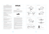
ACCESSORY RAIL CONNECTORS (ARCs)
ARCs are mounted to the sides of the helmet to allow for quick yet secure donning or dofng of various
headborne accessories.
ARC ADAPTERS
The following adapters are commonly used for attaching accessories to
the Ops-Core FAST Helmet: Picatinny & Wing-Loc Adapters (A), O2 Single
Strap Kit (B), and 36mm Goggle Swivel Clip Kit (C).
A
TOP RAIL
Top Rail can accommodate
Picatinny Adapters, which
connect devices compatible with
1911 Picatinny Rail, and Wing-Loc
Adapters, which provide a base
to mount a variety of headborne
accessories.
B
RAIL CORNER
Rail corner allows for instant and
secure snap-in attachment of
Para-Flite and Carleton O2 masks
with O2 Single Strap Kit.
C
BACK RAIL
Goggle Swivel Clips, attached
to your choice of goggles, can
quickly clip into the back rail
while allowing freedom
of rotation.
Picatinny
Adapter
Wing-Loc
Adapter
O2 Strap Kit
(Not Included)
36mm Goggle Swivel Clips
(Not Included)
12

Identity Patch
Additional
Velcro
Cabling
Camera
TOP VIEW REAR VIEW
EXTERIOR LOOP
Apply hook fastener to the bottom of a device and place device on top of the loop on the outside of the
Ops-Core FAST Helmet shell.
13

Front EPP Pad
Fitband Comfort Pad
2
DETACH FITBAND
Place your index nger behind the center of
the Fitband Comfort Pad and carefully bend
away from the Front EPP Pad as shown. Pinch the
Fitband Comfort Pad and use your thumb to slide
the pad sideways ½” towards the center of the helmet
along the Front EPP Pad. Repeat on both sides until the pad
is released from the key slots.
NOTE: DO NOT PULL THE FITBAND COMFORT PAD AWAY
FROM THE FRONT EPP PAD OR YOU MAY BREAK THE
FRONT EPP PAD KEY SLOTS.
COMMs HEADSET
The liner system is compatible with a variety of COMMs headsets and hearing protection devices. Instructions
for use with headband style COMMs is below.
1
RELOCATE TOP PADS
Position the top pads in the helmet so there is enough space for
the headband of the headset to sit in between them.
3
INSERT HEADBAND
Flip the Comfort Pad / Fitband away from the front
impact liner and slide the headset headband around
it as shown. This will position the headset’s headband
on the outside of the helmet Fitband so that it does
not create a pressure point when you tighten the
Occ-Dial Adjustment Knob.
4
REATTCH FITBAND
Reattach the Comfort Pad / Fitband to the key-slots in the front
impact liner by bending the pad in the center and pushing on the
rivets (one at a time) with your thumb while at the same time
sliding them toward the sides of the helmet.
14

STANDARD RECOMMENDED MAINTENANCE
Perform the following recommended maintenance procedures before and after each use. If any defects are
found, the damaged components should be replaced before use.
MAINTENANCE SCHEDULE
1
Clean the helmet with a mild detergent and water.*
2
Check that the chinstrap screws are tight using a athead screwdriver.
3
Clean the Exterior Loop for dust and dirt by using air pressure.
4
Visually check the Modular Bungee Shroud and Skeleton ARCs for signs of breakage.
5
Visually check the Fitband for signs of breakage.
6
Check that the Occ-Dial Adjustment Knob works properly.
7
Check that the chinstrap does not have any damage and that the buckle latches and releases properly.
*The whole helmet can be rinsed in fresh water.
15

Our team of dedicated customer service and support professionals is highly trained on all aspects of our products
and is available to assist you with all your needs, including checking the status of your order, billing, warranties
and returns, orders, replacement parts, and technical support.
REPLACEMENT PARTS
Ops-Core Customer Service
+1 617.670.3547
support@ops-core.com
16

OPERATOR NOTES
17

WARRANTY
Unless an individual product is covered by a separately issued warranty, Gentex warrants that all ballistic helmet shells
will be free from defects in material or workmanship under normal use and service for a period of five (5) years from
the date of delivery. Unless an individual product is covered by a separately issued warranty, Gentex warrants that
all helmet components, accessories, peripherals, and parts will be free from defects in material or workmanship under
normal use and service for a period one (1) year from the date of delivery. All repair covered by this warranty shall be
performed at Gentex’s factory, or other such warranty repair facilities of Gentex as designated by Gentex unless Gentex
specifically directs that repair services be performed at another location. Any defect corrected and found to be within
this scope of the warranty will be repaired by Gentex and all charges for labor and material will be borne by Gentex.
If it is determined that either no fault exists in Gentex, or the damage to be repaired was caused by negligence of the
user, its agents, employees or customers, you agree to pay all charges associated with each such repair. No statement,
recommendation or assistance made or offered by Gentex through its representatives to the user, its agents, employees,
or customers in connection with the purpose or intended use of any Gentex’s product shall be or constitute a waiver by
Gentex of any of the provisions of this warranty or change Gentex’s liability under this warranty.
EXCEPT WHERE PROHIBITED BY LAW, THE WARRANTY DESCRIBED ABOVE CONSTITUTES THE SOLE WARRANTY MADE
BY GENTEX EITHER EXPRESSED OR IMPLIED. THERE ARE NO OTHER WARRANTIES EXPRESSED OR IMPLIED THAT EXTEND
BEYOND THE FACE HEREOF, HEREIN, INCLUDING THE IMPLIED WARRANTIES OF MERCHANTABILITY AND FITNESS
FOR A PARTICULAR PURPOSE. IN NO EVENT SHALL GENTEX BE LIABLE FOR ANY INCIDENTAL, CONSEQUENTIAL, OR
SPECIAL DAMAGES EVEN IF ADVISED OF SUCH DAMAGES, AND THE USER, ITS AGENTS, EMPLOYEES, OR CUSTOMERS
REMEDIES SHALL BE LIMITED TO SOLELY TO THE REPAIR OR REPLACEMENT OF NONCONFORMING UNITS OR PARTS,
WHICH AMOUNT SHALL NOT EXCEED THE TOTAL PURCHASE PRICE OF THE PRODUCT UNDER WARRANTY.
Any tampering, misuse or negligence in handling or use of the product renders the warranty void. Further, the warranty
is void if, at any time, the user, its agents, employees or customers attempts to make any internal changes to any of
the components of a product; if at any time the power supplied to any part of the product exceeds the rated tolerance;
if any external device attached by the user, its agents, employees or customers creates conditions exceeding the
tolerance of the product; or if any time the serial number plate is removed or defaced. OPERATION OF THE PRODUCTS
THAT RENDERS THIS WARRANTY VOID WILL BE DEFINED TO INCLUDE ALL OF THE POSSIBILITIES DESCRIBED IN THIS
SECTION, TOGETHER WITH ANY PRACTICE THAT RESULTS IN CONDITIONS EXCEEDING THE DESIGN TOLERANCE OF
THE PRODUCTS.
WARNING
This helmet provides LIMITED protection for the head and does not offer any protection against neck, spinal, or certain
types of brain injuries including those caused by rotational forces. Some hazards can exceed this helmet’s specified
ability to provide protection and could cause serious injuries or death. This helmet is made to absorb the energy of a
blow by partial destruction or damage to the shell, liner and the harness, and even though such damage may not be
readily apparent, any helmet subjected to severe impact should be replaced. This helmet is designed to help protect
from bumps, scratches, and concussion. This helmet is not intended for use in white water classes 5 and 6 as given by
the International Canoe Federation. For adequate protection this helmet must be fit and adjusted properly to the user.
Inspect the helmet before each use. Make sure the shell components are not damaged, cracked, deformed, loose or
showing signs of excessive wear. Do not remove or alter the front, top, side or back impact pads or modify any or the
original component parts of the helmet, other than as recommended by the helmet manufacturer. Replacing the ½”
thick impact pads with the supplied Ops-Core ¾” impact pads will not adversely affect impact performance. However,
by removing the pads completely or repositioning them, impact attenuation performance could be adversely affected.
Helmets should not be adapted for the purpose of fitting attachments in any way not recommended by the helmet
manufacturer. Do not apply paint, solvents, adhesives, or self-adhesive labels except in accordance with instructions
from the manufacturer as they could degrade helmet integrity and resulting performance. Clean shell with soap and
lukewarm water. Internal comfort pads may be hand washed and air dried.
WARNING & WARRANTY
18


/