Supermicro 1012A-MTF User manual
- Category
- Server barebones
- Type
- User manual

A+ Server 1012A-MTF
SUPER
®
USER’S MANUAL
1.0a

ii
The information in this User’s Manual has been carefully reviewed and is believed to be accurate.
The vendor assumes no responsibility for any inaccuracies that may be contained in this document,
makes no commitment to update or to keep current the information in this manual, or to notify any
person or organization of the updates. Please Note: For the most up-to-date version of this
manual, please see our web site at www.supermicro.com.
Super Micro Computer, Inc. ("Supermicro") reserves the right to make changes to the product
described in this manual at any time and without notice. This product, including software and docu-
mentation, is the property of Supermicro and/or its licensors, and is supplied only under a license.
Any use or reproduction of this product is not allowed, except as expressly permitted by the terms
of said license.
IN NO EVENT WILL SUPERMICRO BE LIABLE FOR DIRECT, INDIRECT, SPECIAL, INCIDENTAL,
SPECULATIVE OR CONSEQUENTIAL DAMAGES ARISING FROM THE USE OR INABILITY TO
USE THIS PRODUCT OR DOCUMENTATION, EVEN IF ADVISED OF THE POSSIBILITY OF
SUCH DAMAGES. IN PARTICULAR, SUPERMICRO SHALL NOT HAVE LIABILITY FOR ANY
HARDWARE, SOFTWARE, OR DATA STORED OR USED WITH THE PRODUCT, INCLUDING THE
COSTS OF REPAIRING, REPLACING, INTEGRATING, INSTALLING OR RECOVERING SUCH
HARDWARE, SOFTWARE, OR DATA.
Any disputes arising between manufacturer and customer shall be governed by the laws of Santa
Clara County in the State of California, USA. The State of California, County of Santa Clara shall
be the exclusive venue for the resolution of any such disputes. Super Micro's total liability for all
claims will not exceed the price paid for the hardware product.
FCC Statement: This equipment has been tested and found to comply with the limits for a Class A
digital device pursuant to Part 15 of the FCC Rules. These limits are designed to provide reasonable
protection against harmful interference when the equipment is operated in a commercial environ-
ment. This equipment generates, uses, and can radiate radio frequency energy and, if not installed
and used in accordance with the manufacturer’s instruction manual, may cause harmful interference
with radio communications. Operation of this equipment in a residential area is likely to cause harmful
interference, in which case you will be required to correct the interference at your own expense.
California Best Management Practices Regulations for Perchlorate Materials: This Perchlorate warn-
ing applies only to products containing CR (Manganese Dioxide) Lithium coin cells. “Perchlorate
Material-special handling may apply. See www.dtsc.ca.gov/hazardouswaste/perchlorate”
WARNING: Handling of lead solder materials used in this
product may expose you to lead, a chemical known to the
State of California to cause birth defects and other repro-
ductive harm.
Manual Revision 1.0a
Release Date: January 16, 2014
Unless you request and receive written permission from Super Micro Computer, Inc., you may not
copy any part of this document.
Information in this document is subject to change without notice. Other products and companies
referred to herein are trademarks or registered trademarks of their respective companies or mark
holders.
Copyright © 2014 by Super Micro Computer, Inc.
All rights reserved.
Printed in the United States of America

Preface
iii
Preface
About This Manual
This manual is written for professional system integrators and PC technicians. It
provides information for the installation and use of the A+ Server 1012A-MTF. In-
stallation and maintenance should be performed by experienced technicians only.
The A+ Server 1012A-MTF is a high-end server based on the CSE-813MT-350CB
1U rackmount chassis and the MB-H8SML-iF single processor serverboard.
Manual Organization
Chapter 1: Introduction
The rst chapter provides a checklist of the main components included with the
server system and describes the main features of the MB-H8SML-iF serverboard
and the CSE-813MT-350CB chassis.
Chapter 2: Server Installation
This chapter describes the steps necessary to install the A+ Server 1012A-MTF into
a rack and check out the server conguration prior to powering up the system. If
your server was ordered without processor and memory components, this chapter
will refer you to the appropriate sections of the manual for their installation.
Chapter 3: System Interface
Refer here for details on the system interface, which includes the functions and
information provided by the control panel on the chassis as well as other LEDs
located throughout the system.

A+ Server 1012A-MTF User's Manual
iv
iv
Chapter 4: Warning Statements for AC Systems
You should thoroughly familiarize yourself with this chapter for a general overview
of safety precautions that should be followed when installing and servicing the A+
Server 1012A-MTF.
Chapter 5: Advanced Serverboard Setup
Chapter 5 provides detailed information on the MB-H8SML-iF serverboard, includ-
ing the locations and functions of connections, headers and jumpers. Refer to this
chapter when adding or removing processors or main memory and when recong-
uring the serverboard.
Chapter 6: Advanced Chassis Setup
Refer to Chapter 6 for detailed information on the CSE-813MT-350CB server chas-
sis. You should follow the procedures given in this chapter when installing, removing
or reconguring SATA or peripheral drives and when replacing system power supply
modules and cooling fans.
Chapter 7: BIOS
The BIOS chapter includes an introduction to BIOS and provides detailed informa-
tion on running the CMOS Setup Utility.
Appendix A: POST Error Beep Codes
Appendix B: UEFI BIOS Recovery Instructions
Appendix C: System Specications

Preface
v
Contents
Chapter 1 Introduction
1-1 Overview ......................................................................................................... 1-1
1-2 Motherboard Features ..................................................................................... 1-2
Processors ...................................................................................................... 1-2
Memory ........................................................................................................... 1-2
Serial ATA (SATA)............................................................................................ 1-2
I/O Ports .......................................................................................................... 1-2
1-3 Server Chassis Features ................................................................................ 1-3
System Power ................................................................................................. 1-3
SATA Subsystem ............................................................................................. 1-3
Control Panel .................................................................................................. 1-3
Cooling System ............................................................................................... 1-3
1-4 Contacting Supermicro .................................................................................... 1-5
Chapter 2 Server Installation
2-1 Overview ......................................................................................................... 2-1
2-2 Unpacking the System .................................................................................... 2-1
2-3 Preparing for Setup ......................................................................................... 2-1
Choosing a Setup Location ............................................................................. 2-1
2-4 Warnings and Precautions .............................................................................. 2-2
Rack Precautions ............................................................................................ 2-2
Server Precautions .......................................................................................... 2-2
Rack Mounting Considerations ....................................................................... 2-3
Ambient Operating Temperature ................................................................ 2-3
Reduced Airow ......................................................................................... 2-3
Mechanical Loading ................................................................................... 2-3
Circuit Overloading ..................................................................................... 2-3
Reliable Ground ......................................................................................... 2-3
2-5 Installing the System into a Rack ................................................................... 2-4
Identifying the Sections of the Rack Rails ...................................................... 2-4
Installing the Rear Inner Rails ........................................................................ 2-4
Installing the Rack Rails ................................................................................. 2-5
Installing the Server into the Rack .................................................................. 2-6
Installing the Server into a Telco Rack ........................................................... 2-7

A+ Server 1012A-MTF User's Manual
vi
Chapter 3 System Interface
3-1 Overview ......................................................................................................... 3-1
3-2 Control Panel Buttons ..................................................................................... 3-2
3-3 Control Panel LEDs ........................................................................................ 3-2
Overheating ..................................................................................................... 3-3
3-4 Drive Carrier LEDs .......................................................................................... 3-4
3-5 Power Supply LEDs ........................................................................................ 3-4
Chapter 4 Standardized Warning Statements for AC Systems
4-1 About Standardized Warning Statements ....................................................... 4-1
Warning Denition ........................................................................................... 4-1
Installation Instructions .................................................................................... 4-4
Circuit Breaker ................................................................................................ 4-5
Power Disconnection Warning ........................................................................ 4-6
Equipment Installation ..................................................................................... 4-8
Restricted Area ................................................................................................ 4-9
Battery Handling ............................................................................................ 4-10
Redundant Power Supplies .......................................................................... 4-12
Backplane Voltage ........................................................................................ 4-13
Comply with Local and National Electrical Codes ........................................ 4-14
Product Disposal ........................................................................................... 4-15
Hot Swap Fan Warning ................................................................................. 4-16
Power Cable and AC Adapter ...................................................................... 4-18
Chapter 5 Advanced Motherboard Setup
5-1 Handling the Motherboard .............................................................................. 5-1
Precautions ..................................................................................................... 5-1
Unpacking ....................................................................................................... 5-1
5-2 Processor and Heatsink Installation................................................................ 5-2
5-3 Mounting the Motherboard into a Chassis ...................................................... 5-4
5-4 Installing Memory ............................................................................................ 5-4
DIMM Module Population Conguration .................................................... 5-6
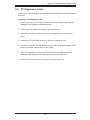
5-5 PCI Expansion Cards ...................................................................................... 5-7
5-6 I/O Port and Control Panel Connections ........................................................ 5-8
Front Control Panel ......................................................................................... 5-8
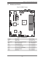
5-7 Motherboard Details ........................................................................................ 5-9
5-8 Connector Denitions ....................................................................................5-11
5-9 Jumper Settings ............................................................................................ 5-18
Explanation of Jumpers ................................................................................ 5-18
5-10 Onboard Indicators ........................................................................................ 5-21
5-11 SATA Drive Connections ............................................................................... 5-22

Preface
vii
viii
5-12 Enabling SATA RAID ..................................................................................... 5-23
Serial ATA (SATA).......................................................................................... 5-23
Installing the OS/SATA Driver ....................................................................... 5-23
Building a Driver Diskette ......................................................................... 5-23
Enabling SATA RAID in the BIOS ................................................................. 5-24
Using the Adaptec RAID Utility ..................................................................... 5-25
Installing the RAID Driver During OS Installation ......................................... 5-25
5-13 Installing Software ......................................................................................... 5-26
SuperDoctor III .............................................................................................. 5-27
5-14 Onboard Battery ............................................................................................ 5-28
Chapter 6 Advanced Chassis Setup
6-1 Static-Sensitive Devices .................................................................................. 6-1
Precautions ..................................................................................................... 6-1
Unpacking ....................................................................................................... 6-1
6-2 Control Panel .................................................................................................. 6-2
6-3 Removing the Chassis Cover ......................................................................... 6-3
6-4 System Fans ................................................................................................... 6-4
6-5 Drive Bay Installation/Removal ....................................................................... 6-4
Removing the Front Bezel .............................................................................. 6-4
Accessing the Drive Bays ............................................................................... 6-5
Hard Drive Installation ..................................................................................... 6-5
6-6 Power Supply .................................................................................................. 6-8
Chapter 7 BIOS
7-1 Introduction ...................................................................................................... 7-1
7-2 Main Menu ...................................................................................................... 7-2
7-3 Advanced Settings Menu ................................................................................ 7-3
7-4 Security Menu ............................................................................................... 7-16
7-5 Boot Menu ..................................................................................................... 7-16
7-6 Exit Menu ...................................................................................................... 7-18
Appendix A POST Error Beep Codes
Appendix B UEFI BIOS Recovery Instructions
Appendix C System Specications

A+ Server 1012A-MTF User's Manual
viii
v
Notes

Chapter 1
Introduction
1-1 Overview
The A+ Server 1012A-MTF is a high-end server comprised of the SC813MT-350CB
1U chassis and the H8SML-iF single processor motherboard. Refer to our web
site for information on operating systems that have been certied for use with the
system (www.supermicro.com).
In addition to the motherboard and chassis, various hardware components have
been included with the 1012A-MTF, as listed below:
•Three sets of 4-cm counter-rotating fans (FAN-0065L4)
•One passive CPU heatsink (SNK-P0026)
•One air shroud for 1U system (MCP-310-81303-0B)
•One riser card for one PCI-E 2.0 x8 add-on card (CSE-RR1U-E8)
•SATA Accessories
One SATA backplane (BPN-SAS-815TQ)
Four 3.5" hard drive carriers (MCP-220-00075-0B)
One SATA cable (CBL-0186L)
•One rackmount kit (MCP-290-00102-0N and MCP-290-00107-ON)
•A+ Server 1012A-MTF Quick Reference Guide
Note: For your system to work properley, please follow the links below to download
all necessary drivers/utilities and the user’s manual for your server.
•Product manuals: http://www.supermicro.com/support/manuals/
•Product drivers and utilities: ftp://ftp.supermicro.com
•Product safety information:
http://super-dev/about/policies/safety_information.cfm
For support, email [email protected].
Chapter 1: Introduction
1-1

1-2
A+ Server 1012A-MTF User's Manual
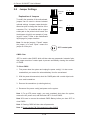
1-2 Motherboard Features
The H8SML-iF serverboard is based on the AMD SR5650 and SP5100 chipsets.
Below are the main features of the H8SML-iF (see Figure 1-1 for a block diagram
of the chipset).
Processors
The H8SML-iF supports one AMD Opteron 3000 series (AMD Socket AM3+ type)
processor. Please refer to the motherboard description pages on our web site for
a complete listing of supported processors.
Memory
The H8SML-iF serverboard contains four (4) single/dual channel DIMM slots sup-
porting up to 32 GB of Unbuffered ECC/non-ECC DDR3-1600/1333/1066 Mhz
speed, 1 GB, 2 GB, 4 GB or 8 GB size SDRAM memory. Please refer to Chapter
5 for installing memory.
Serial ATA (SATA)
Serial ATA (SATA) is a physical storage interface that employs a single cable with a
minimum of four wires to create a point-to-point connection between devices. This
connection is a serial link that supports a SATA transfer rate from 150 MBps. The
serial cables used in SATA are thinner than the traditional cables used in Parallel
ATA (PATA) and can extend up to one meter in length, compared to only 40 cm for
PATA cables. Overall, SATA provides better functionality than PATA.
I/O Ports
The color-coded I/O ports include one COM port, a VGA (monitor) port, two USB 2.0
ports, PS/2 mouse and keyboard ports and two gigabit Ethernet ports. A dedicated
IPMI LAN port is also included.

1-3
Chapter 1: Introduction
1-3 Server Chassis Features
The following is a general outline of the main features of the SC813MT-350CB
chassis.
System Power
When congured as a 1012A-MTF, the SC813MT chassis includes a single 350W
power supply.
SATA Subsystem
For the 1012A-MTF, the SC813MT chassis was designed to support four SATA
hard drives, which are hot-swappable units.
Note: The operating system you use must have RAID support to enable the
hot-swap capability of the SATA drives (system-based RAID is not available for
SATA).
Control Panel
The SC813MT control panel provides important system monitoring and control
information. LEDs indicate power on, network activity, hard disk drive activity and
system overheat conditions. The control panel also includes a main power button
and a system reset button. The front of the chassis also includes a COM port and
two USB serial ports for easy access.
Cooling System
The SC813MT chassis has an innovative cooling design that features three 4-cm
high-performance system cooling fans. Each of these fans plug into a chassis fan
header on the motherboard.
A fan speed control setting in IPMI allows fan speed to be determined by system
temperature.

1-4
A+ Server 1012A-MTF User's Manual
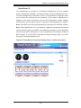
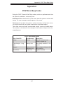
Figure 1-1. Chipset:
System Block Diagram
Note: This is a general block diagram. Please see Chapter 5 for details.
UDIMM/1600 1B
UDIMM/1600 1A
SOCKET
AM3R2
CPU
H
T
3
L
i
n
k
16
/16
-
2.6
GH
z
UDIMM/1600 2B
UDIMM/1600 2A
PCI-E GEN2 X8
Slot7 PCI-E 2.0 x8 (in x16)
SATA x6
Slot5 PCI-E 2.0 x8
PCI-E GEN2 x1
INTEL
82574L
RJ45
A-Link
SP5100
BMC
VGA
WPCM450-R
PCI
LPC
SMBus
SIO
W83527HG
HWM
W83795G
SPI Flash
KB/MS
RMII
DDR2 SDRAM
64MB X16
PSU I2C
IPMB
VGA
FE PHY
RTL8201N
RJ45
Clock Gen
TPM
SR5650
COM2
COM1
RJ45
INTEL
82574L
Slot6 PCI-E 2.0 x4 (in x8)
SWITCH
PCI-E GEN2 x1
7xUSB
LSI 2308
SAS x8
PCI-E GEN2 X8
PCI-E GEN2 X4

1-5
Chapter 1: Introduction
1-4 Contacting Supermicro
Headquarters
Address: Super Micro Computer, Inc.
980 Rock Ave.
San Jose, CA 95131 U.S.A.
Tel: +1 (408) 503-8000
Fax: +1 (408) 503-8008
Email: [email protected] (General Information)
[email protected] (Technical Support)
Web Site: www.supermicro.com
Europe
Address: Super Micro Computer B.V.
Het Sterrenbeeld 28, 5215 ML
's-Hertogenbosch, The Netherlands
Tel: +31 (0) 73-6400390
Fax: +31 (0) 73-6416525
Email: [email protected] (General Information)
[email protected] (Technical Support)
[email protected] (Customer Support)
Web Site: www.supermicro.com
Asia-Pacic
Address: Super Micro Computer, Inc.
3F, No. 150, Jian 1st Rd.
Zhonghe Dist., New Taipei City 235
Taiwan (R.O.C)
Tel: +886-(2) 8226-3990
Fax: +886-(2) 8226-3992
Email: [email protected]
Tel: +886-(2)-8226-3990
Web Site: www.supermicro.com.tw

1-6
A+ Server 1012A-MTF User's Manual
Notes

Chapter 2: Server Installation
2-1
Chapter 2
Server Installation
2-1 Overview
This chapter provides a quick setup checklist to get your A+ Server 1012A-MTF
up and running. Following the steps in the order given should enable you to have
the system operational within a minimal amount of time. This quick setup assumes
that your A+ Server 1012A-MTF system has come to you with the processor and
memory preinstalled. If your system is not already fully integrated with a mother-
board, processor, system memory etc., please turn to the chapter or section noted
in each step for details on installing specic components.
2-2 Unpacking the System
You should inspect the box the A+ Server 1012A-MTF was shipped in and note if
it was damaged in any way. If the server itself shows damage, you should le a
damage claim with the carrier who delivered it.
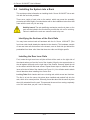
2-3 Preparing for Setup
Decide on a suitable location for the rack unit that will hold the A+ Server 1012A-
MTF. It should be situated in a clean, dust-free area that is well ventilated. Avoid
areas where heat, electrical noise and electromagnetic elds are generated. You
will also need it placed near a grounded power outlet. Read the Rack and Server
Precautions in the next section.
The box the A+ Server 1012A-MTF was shipped in should include two sets of rail
assemblies, six rail mounting brackets and the mounting screws you will need to
install the system into the rack. Follow the steps in the order given to complete the
installation process in a minimal amount of time. Please read this section in its en-
tirety before you begin the installation procedure outlined in the sections that follow.
Choosing a Setup Location
•Leave enough clearance in front of the rack to enable you to open the front door
completely (~25 inches) and approximately 30 inches of clearance in the back
of the rack to allow for sufcient airow and ease in servicing.This product is for

2-2
A+ Server 1012A-MTF User's Manual
installation only in a Restricted Access Location (dedicated equipment rooms,
service closets and the like).
•This product is not suitable for use with visual display work place devices
acccording to §2 of the the German Ordinance for Work with Visual Display
Units.
2-4 Warnings and Precautions
Rack Precautions
•Ensure that the leveling jacks on the bottom of the rack are fully extended to
the oor with the full weight of the rack resting on them.
•In single rack installation, stabilizers should be attached to the rack. In multiple
rack installations, the racks should be coupled together.
•Always make sure the rack is stable before extending a component from the
rack.
•You should extend only one component at a time - extending two or more si-
multaneously may cause the rack to become unstable.
Server Precautions
•Review the electrical and general safety precautions in Chapter 4.
•Determine the placement of each component in the rack before you install the
rails.
•Install the heaviest server components on the bottom of the rack rst, and then
work up.
•Use a regulating uninterruptible power supply (UPS) to protect the server from
power surges, voltage spikes and to keep your system operating in case of a
power failure.
•Allow the hot plug SATA drives and power supply modules to cool before touch-
ing them.
•Always keep the rack's front door and all panels and components on the servers
closed when not servicing to maintain proper cooling.

Chapter 2: Server Installation
2-3
Rack Mounting Considerations
Ambient Operating Temperature
If installed in a closed or multi-unit rack assembly, the ambient operating tempera-
ture of the rack environment may be greater than the ambient temperature of the
room. Therefore, consideration should be given to installing the equipment in an
environment compatible with the manufacturer’s maximum rated ambient tempera-
ture (Tmra).
Reduced Airow
Equipment should be mounted into a rack so that the amount of airow required
for safe operation is not compromised.
Mechanical Loading
Equipment should be mounted into a rack so that a hazardous condition does not
arise due to uneven mechanical loading.
Circuit Overloading
Consideration should be given to the connection of the equipment to the power
supply circuitry and the effect that any possible overloading of circuits might have
on overcurrent protection and power supply wiring. Appropriate consideration of
equipment nameplate ratings should be used when addressing this concern.
Reliable Ground
A reliable ground must be maintained at all times. To ensure this, the rack itself
should be grounded. Particular attention should be given to power supply connec-
tions other than the direct connections to the branch circuit (i.e. the use of power
strips, etc.).
Warning: To prevent bodily injury when mounting or servicing this unit in a
rack, you must take special precautions to ensure that the system remains
stable. The following guidelines are provided to ensure your safety:
•This unit should be mounted at the bottom of the rack if it is the only unit in
the rack.
•When mounting this unit in a partially lled rack, load the rack from the bottom
to the top with the heaviest component at the bottom of the rack.
•If the rack is provided with stabilizing devices, install the stabilizers before
mounting or servicing the unit in the rack.

2-4
A+ Server 1012A-MTF User's Manual
2-5 Installing the System into a Rack
This section provides information on installing the A+ Server 1012A-MTF into a rack
unit with the rack rails provided.
There are a variety of rack units on the market, which may mean the assembly
procedure will differ slightly. You should also refer to the installation instructions that
came with the rack unit you are using.
Stability hazard. The rack stabilizing mechanism must be in place, or the
rack must be bolted to the oor before you slide the unit out for servicing.
Failure to stabilize the rack can cause the rack to tip over.
Identifying the Sections of the Rack Rails
You may have received rack rail hardware with the A+ Server 1012A-MTF. (Two
front inner rails should already be attached to the chassis.) This hardware consists
of two rear inner rails that secure to the chassis, one on each side just behind the
preinstalled front inner rails. Note that these two rails are left/right specic.
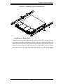
Installing the Rear Inner Rails
First, locate the right rear inner rail (the rail that will be used on the right side of
the chassis when you face the front of the chassis). Align the two square holes on
the rail against the hooks on the right side of the chassis. Securely attach the rail
to the chassis with M4 at head screws. Repeat these steps to install the left rear
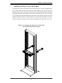
inner rail to the left side of the chassis (see Figure 2-1). You will also need to attach
the rail brackets when installing into a telco rack.
Locking Tabs: Both chassis rails have a locking tab, which serves two functions.
The rst is to lock the server into place when installed and pushed fully into the
rack, which is its normal position. Secondly, these tabs also lock the server in place
when fully extended from the rack. This prevents the server from coming completely
out of the rack when you pull it out for servicing.

Chapter 2: Server Installation
2-5
Installing the Rack Rails
Determine where you want to place the A+ Server 1012A-MTF in the rack. Position
the chassis rail guides at the desired location in the rack, keeping the sliding rail
guide facing the inside of the rack. Screw the assembly securely to the rack using the
brackets provided. Attach the other assembly to the other side of the rack, making
sure that both are at the exact same height and with the rail guides facing inward.
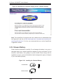
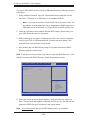
Figure 2-1. Installing Rear Inner Chassis Rails

2-6
A+ Server 1012A-MTF User's Manual
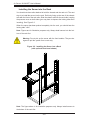
Figure 2-2. Installing the Server into a Rack
(with optional front bezel shown)
Installing the Server into the Rack
You should now have rails attached to both the chassis and the rack unit. The next
step is to install the server into the rack. Do this by lining up the rear of the chassis
rails with the front of the rack rails. Slide the chassis rails into the rack rails, keeping
the pressure even on both sides (you may have to depress the locking tabs when
inserting). See Figure 2-2.
When the server has been pushed completely into the rack, you should hear the
locking tabs "click".
Note: Figures are for illustrative purposes only. Always insall servers into the bot-
tom of the rack rst.
Note: The gure above is for illustrative purposes only. Always install servers to
the bottom of the rack rst.
Warning: Do not pick up the server with the front handles. They are de-
signed to pull the system from a rack only.
Page is loading ...
Page is loading ...
Page is loading ...
Page is loading ...
Page is loading ...
Page is loading ...
Page is loading ...
Page is loading ...
Page is loading ...
Page is loading ...
Page is loading ...
Page is loading ...
Page is loading ...
Page is loading ...
Page is loading ...
Page is loading ...
Page is loading ...
Page is loading ...
Page is loading ...
Page is loading ...
Page is loading ...
Page is loading ...
Page is loading ...
Page is loading ...
Page is loading ...
Page is loading ...
Page is loading ...
Page is loading ...
Page is loading ...
Page is loading ...
Page is loading ...
Page is loading ...
Page is loading ...
Page is loading ...
Page is loading ...
Page is loading ...
Page is loading ...
Page is loading ...
Page is loading ...
Page is loading ...
Page is loading ...
Page is loading ...
Page is loading ...
Page is loading ...
Page is loading ...
Page is loading ...
Page is loading ...
Page is loading ...
Page is loading ...
Page is loading ...
Page is loading ...
Page is loading ...
Page is loading ...
Page is loading ...
Page is loading ...
Page is loading ...
Page is loading ...
Page is loading ...
Page is loading ...
Page is loading ...
Page is loading ...
Page is loading ...
Page is loading ...
Page is loading ...
Page is loading ...
Page is loading ...
Page is loading ...
Page is loading ...
Page is loading ...
Page is loading ...
Page is loading ...
Page is loading ...
Page is loading ...
Page is loading ...
Page is loading ...
Page is loading ...
Page is loading ...
Page is loading ...
Page is loading ...
Page is loading ...
Page is loading ...
Page is loading ...
Page is loading ...
Page is loading ...
Page is loading ...
Page is loading ...
Page is loading ...
Page is loading ...
Page is loading ...
Page is loading ...
-
 1
1
-
 2
2
-
 3
3
-
 4
4
-
 5
5
-
 6
6
-
 7
7
-
 8
8
-
 9
9
-
 10
10
-
 11
11
-
 12
12
-
 13
13
-
 14
14
-
 15
15
-
 16
16
-
 17
17
-
 18
18
-
 19
19
-
 20
20
-
 21
21
-
 22
22
-
 23
23
-
 24
24
-
 25
25
-
 26
26
-
 27
27
-
 28
28
-
 29
29
-
 30
30
-
 31
31
-
 32
32
-
 33
33
-
 34
34
-
 35
35
-
 36
36
-
 37
37
-
 38
38
-
 39
39
-
 40
40
-
 41
41
-
 42
42
-
 43
43
-
 44
44
-
 45
45
-
 46
46
-
 47
47
-
 48
48
-
 49
49
-
 50
50
-
 51
51
-
 52
52
-
 53
53
-
 54
54
-
 55
55
-
 56
56
-
 57
57
-
 58
58
-
 59
59
-
 60
60
-
 61
61
-
 62
62
-
 63
63
-
 64
64
-
 65
65
-
 66
66
-
 67
67
-
 68
68
-
 69
69
-
 70
70
-
 71
71
-
 72
72
-
 73
73
-
 74
74
-
 75
75
-
 76
76
-
 77
77
-
 78
78
-
 79
79
-
 80
80
-
 81
81
-
 82
82
-
 83
83
-
 84
84
-
 85
85
-
 86
86
-
 87
87
-
 88
88
-
 89
89
-
 90
90
-
 91
91
-
 92
92
-
 93
93
-
 94
94
-
 95
95
-
 96
96
-
 97
97
-
 98
98
-
 99
99
-
 100
100
-
 101
101
-
 102
102
-
 103
103
-
 104
104
-
 105
105
-
 106
106
-
 107
107
-
 108
108
-
 109
109
-
 110
110


Supermicro 1012A-MTF User manual
- Category
- Server barebones
- Type
- User manual
Ask a question and I''ll find the answer in the document
Finding information in a document is now easier with AI
Related papers
-
Supermicro MBD-H8SML-IF-O User manual
-
Supermicro SC846X User manual
-
-
-
-
-
-
-
-
Other documents
-
 Supero SC835BTQ-R1K28B User manual
-
Gateway Server User manual
-
-
Gateway E-9722R User manual
-
SUPER MICRO Computer H8SCM-F User manual
-
SUPER MICRO Computer Server 5017C-MTF User manual
-
Gigabyte G-MAX TA3 User manual
-
H3C UIS-Cell 3000 G3 User manual
-
SUPER MICRO Computer 5016T-TB User manual
-
