Page is loading ...

1-1
Cisco XR 12416 Router Installation Guide
OL-13833-01
CHAPTER
1
Product Overview
This chapter provides an overview of the Cisco XR 12416 router. It contains
physical descriptions of the router hardware and major components, as well as
functional descriptions of the hardware-related features.
Physical and Functional Description of Router
The Cisco XR 12416 router chassis is a sheet-metal enclosure that houses router
components. The major components consist of three power supplies, upper and
lower line card cages, a switch fabric card cage, and upper and lower blower
modules. Power is distributed to these components over the chassis backplane.
All router models contain the following major components (Figure 1-1):
• Power shelf and power supplies—Three AC or DC power entry modules
(PEMs) provide power to the router. See the “AC and DC Power Subsystems”
section on page 1-4 for additional information.
• Upper blower module—Supplies cooling air to the upper half of the router so
it does not overheat. See the “Blower Module” section on page 1-30 for
additional information.
• Upper and lower cable management brackets—Used to neatly route line card
cables. See the “Upper and Lower Cable Management Brackets” section on
page 1-30 for additional information.

Chapter 1 Product Overview
Physical and Functional Description of Router
1-2
Cisco XR 12416 Router Installation Guide
OL-13833-01
• Upper Line card and Route Processor card cage—Has 8 user-configurable
slots that support a combination of line cards, a route processor (RP), and an
alarm card. See the “Alarm Card and Line Card Overview” section on
page 1-18 for additional information.
• Switch fabric card cage—Located behind the air filter door, this card cage
contains 5 slots for the switch fabric card set. The switch fabric card set is
made up of 3 switch fabric cards (SFCs) and 2 clock scheduler cards (CSCs).
See the “Switch Fabric Overview” section on page 1-16 for additional
information.
• Lower Line card and Route Processor card cage—Has 8 user-configurable
slots that support a combination of line cards, a redundant route processor
(RP), and an alarm card. See the “Alarm Card and Line Card Overview”
section on page 1-18 for additional information.
• Lower blower module—Supplies cooling air to the lower half of the router so
it does not overheat. See the “Blower Module” section on page 1-30 for
additional information.
• Chassis backplane (not shown)—Distributes power to card cages and to the
blower modules.

1-3
Cisco XR 12416 Router Installation Guide
OL-13833-01
Chapter 1 Product Overview
Physical and Functional Description of Router
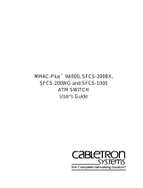
Figure 1-1 Cisco XR 12016 Router Components—Front View
Switch fabric
card cage
(behind filter door)
P
W
R
O
K
F
A
U
L
T
T
E
M
P
I
L
I
M
P
W
R
O
K
F
A
U
L
T
T
E
M
P
I
L
I
M
P
W
R
O
K
F
A
U
L
T
T
E
M
P
I
L
I
M
ALARM
E
N
A
B
L
E
D
F
A
IL
ACO/LT
ALARM
CSC
0
FAIL
1
0
1
2
ENABL
ED
CRITICAL
MAJOR
MINOR
SFC
ACTIVE
0
CARRIER
RX
PKT
ACTIVE
1
CARRIER
RX PKT
ACTIVE
2
CARRIER
RX PKT
ACTIVE
3
CARRIER
RX PKT
Q OC-3/STM-POS
6DS3–SMB P
/
H
/
F
DOWN
LOOP RA LA
CDHNT CD
TX
0
RX
TX
1
RX
TX
2
RX
TX
3
RX
TX
4
RX
TX
5
RX
12DS3–SMB P
/
H
/
F
DOWN
LOOP RA LA
CDHNT CD
TX
0
RX
TX
1
RX
TX
2
RX
TX
3
RX
TX
4
RX
TX
5
RX
TX
6
RX
TX
7
RX
TX
8
RX
TX
9
RX
TX
10
RX
TX
11
RX
A
C
T
I
V
E
C
A
R
R
I
E
R
R
X
P
K
T
OC-48/STM-16-SCPOS
ACTIVE
0
CARRIER
RX CELL
OC-12/STM-4 ATM
FAST ETERNET
SLO
T-0
ROUTE PROCESSOR
SLOT-1
COLL
L
INK
TX
RX
RJ-45
MII
RESE
T
AU
X
CO
N
SO
LE
EJECT
SLOT-0
ROUTE PROCESSOR
SLOT-1
COLL
LINK
TX
RX
RJ-45
MII
RESET
AU
X
C
ON
SOLE
EJECT
FAST ETERNET
ACTIVE
0
CARRIER
RX CELL
OC-12/STM-4 ATM
A
C
T
I
V
E
C
A
R
R
I
E
R
R
X
P
K
T
OC-48/STM-16-SCPOS
12DS3–SMB P
/
H
/
F
DOWN
LOOP RA LA
CDHNT CD
TX
0
RX
TX
1
RX
TX
2
RX
TX
3
RX
TX
4
RX
TX
5
RX
TX
6
RX
TX
7
RX
TX
8
RX
TX
9
RX
TX
10
RX
TX
11
RX
6DS3–SMB P
/
H
/
F
DOWN
LOOP RA LA
CDHNT CD
TX
0
RX
TX
1
RX
TX
2
RX
TX
3
RX
TX
4
RX
TX
5
RX
ACTIVE
0
CARRIER
RX PKT
ACTIVE
1
CARRIER
RX PKT
ACTIVE
2
CARRIER
RX PKT
ACTIVE
3
CARRIER
RX PKT
Q OC-3/STM-POS
ALARM
E
N
A
B
L
E
D
F
A
IL
ACO/LT
ALARM
CS
C
0
FAIL
1
0
1
2
ENABLE
D
CRITICAL
MAJOR
MINOR
SFC
26194
Power shelf and
power supplies
Air filter door
Upper blower
module
Upper cable
management
bracket
Lower cable
management
bracket
Lower blower
module
Upper card cage
Alarm card
RP
Lower card cage
Alarm card

Chapter 1 Product Overview
Physical and Functional Description of Router
1-4
Cisco XR 12416 Router Installation Guide
OL-13833-01
AC and DC Power Subsystems
A router ships with either an AC or DC powered system. Source power connects
to the power shelf at the back of the chassis which route power to the power
supplies, also referred to as power entry modules (PEMs).
Standard AC Power Shelf
The standard AC-input power subsystem consists of a single-level AC-input
power shelf that house three AC power supplies which supply full redundant
power to the router.
The power supplies participate in an N+1 redundant current-sharing scheme that
is divided among all three power supplies. If one power supply fails, the system
can continue to operate temporarily, (depending on your system configuration)
with the remaining two power supplies. Failed power supplies should be replaced
as soon as possible to ensure full redundancy.
Caution To ensure that the chassis configuration complies with the required power
budgets, use the on-line power calculator. Failure to properly verify the
configuration may result in an unpredictable state if one of the power units fails.
Contact your local sales representative for assistance.

1-5
Cisco XR 12416 Router Installation Guide
OL-13833-01
Chapter 1 Product Overview
Physical and Functional Description of Router
Figure 1-2 Standard AC-Input Power Subsystem
Caution A router equipped with the standard AC power subsystem must be operated with
three power supplies installed in the power shelf at all times for electromagnetic
compatibility (EMC).
AC power to the router is provided through power cords connected from AC
power outlets to connectors on back of the power shelf as shown in Figure 1-3.
Figure 1-3 Standard Power Shelf AC-Input Connections
26198
P
W
R
O
K
F
A
U
LT
TE
M
P
I L
IM
P
W
R
O
K
F
A
U
L
T
T
E
M
P
I
LIM
P
W
R
O
K
F
A
U
L
T
T
E
M
P
I L
IM
26199
Power cord
retention clip

Chapter 1 Product Overview
Physical and Functional Description of Router
1-6
Cisco XR 12416 Router Installation Guide
OL-13833-01
Optional AC Power Shelf
The power subsystem consists of a double-level AC-input power shelf with bays
for 4 AC-input power supplies. Figure 1-4 shows the optional power shelf. It
attaches to the top of the router chassis and is secured to the chassis the same way
as the standard AC-input power shelf.
Note A router equipped with the optional AC-input power subsystem stands 77.5 inches
(196.85 cm) tall and does not fit in a standard 7-foot (2.1 m) rack.
The 4 power supplies in the optional power shelf participate in an N+2 redundant
current-sharing scheme in which current sharing is divided among all 4 power
supplies. Up to two power supplies can fail and the system can continue to operate
temporarily, (depending on your system configuration) using the remaining two
power supplies. Failed supplies should be replaced as soon as possible to ensure
full redundancy.
Caution To ensure that the chassis configuration complies with the required power
budgets, use the on-line power calculator. Failure to properly verify the
configuration may result in an unpredictable state if one of the power units fails.
Contact your local sales representative for assistance.

1-7
Cisco XR 12416 Router Installation Guide
OL-13833-01
Chapter 1 Product Overview
Physical and Functional Description of Router
Figure 1-4 Optional AC-Input Power Subsystem
Caution A router equipped with the optional AC power subsystem must be operated with
4 power supplies installed in the power shelf at all times for electromagnetic
compatibility (EMC).
27837
P
W
R
O
K
F
A
U
L
T
T
EM
P
I L
IM
P
W
R
O
K
F
A
U
L
T
T
E
M
P
I L
IM
P
W
R
O
K
F
A
U
L
T
T
EM
P
I L
IM
P
W
R
O
K
F
A
U
LT
T
E
M
P
I L
IM

Chapter 1 Product Overview
Physical and Functional Description of Router
1-8
Cisco XR 12416 Router Installation Guide
OL-13833-01
AC power to the router is provided through power cords connected from AC
power outlets to the connectors on the back of the power shelf as shown in
Figure 1-5.
Figure 1-5 Optional Power Shelf AC-Input Connections
27838
Power cords

1-9
Cisco XR 12416 Router Installation Guide
OL-13833-01
Chapter 1 Product Overview
Physical and Functional Description of Router
AC Power Supplies
Each AC PEM converts 200 to 240 VAC into -48 VDC, which is distributed
through the chassis backplane to all cards, RPs, and the blower modules.
Figure 1-6 identifies the components of a 2500 W AC power supply.
Figure 1-6 2500 W AC Power Supply Components
1 Ejector handle 2 Captive screw
129495
Pwr Ok
Fault
Temp
OC
1
2
Pwr Ok
Fault
Temp
OC

Chapter 1 Product Overview
Physical and Functional Description of Router
1-10
Cisco XR 12416 Router Installation Guide
OL-13833-01
The status LEDs on an AC PEM provide information about the current operational
status of the power supply:
• PWR OK (green)—Indicates that the power supply module is operating
normally.
• FAULT (yellow)—Indicates that a fault is detected within the PEM.
• TEMP (yellow)—Indicates the PEM is in an overtemperature condition and
shutdown has occurred.
• ILMI (yellow)—Indicates the PEM is operating in a current-limiting
condition.
For additional information about troubleshooting AC PEMs, see the
“Troubleshooting an AC Power Supply” section on page 4-5.
DC Power Shelf
A DC-input power subsystem consists of a DC-input power shelf that houses 4
DC PEMs that provide full redundant power to the router. Figure 1-7 shows a
DC-input power shelf.
The chassis is electrically divided between the PEMS. These sections are referred
to as power zones and are labeled accordingly:
• Two PEMs power the upper card cage (Zone 1)
• Two PEMs power the lower card cage (Zone 2)
Each zone provides power to one blower, one alarm card, line cards and route
processor cards.
Zone 2 also supplies power to all switch fabric cards. The result is that there is
less power available for line cards in Zone 2, limiting the number of high-powered
line cards that can be configured in the lower cage.
Caution To ensure that the chassis configuration complies with the required power
budgets, contact your sales representative to provide you with the required power
calculator. Failure to properly verify the configuration may result in an
unpredictable state if one of the power units fails.
Contact your local sales representative for assistance.

1-11
Cisco XR 12416 Router Installation Guide
OL-13833-01
Chapter 1 Product Overview
Physical and Functional Description of Router
In the DC-input power configuration:
• Modules A1 and B1 provide redundant power for system load zone 1 (the
upper blower module and the upper card cage).
• Modules A2 and B2 provide redundant power for system load zone 2 (the
switch fabric card cage, the lower card cage, and the lower blower module).
Figure 1-7 DC-Input Power Shelf
Caution A router configured for source DC operation must be operated with 4 DC-input
PEMs installed at all times for electromagnetic compatibility (EMC).
Note DC PEMs support online insertion and removal (OIR) which means that you can
remove and replace one PEM in each load zone (A1 or B1; A2 or B2) while the
system remains powered on.
DC power to the router is provided from cables from a DC power source that are
connected to threaded terminal studs on the back of the DC-input power shelf as
shown in Figure 1-8.
26201
PWR OK
FAULT
TEMP
PWR OK
FAULT
TEMP
PWR OK
FAULT
TEMP
PWR OK
FAULT
TEMP

Chapter 1 Product Overview
Physical and Functional Description of Router
1-12
Cisco XR 12416 Router Installation Guide
OL-13833-01
Figure 1-8 DC-Input Power Shelf Connections
A1-
A1+
A2-
A2+ B2+
B2-
B1+
B1- Ground
B1
Cover with slotted screw hole;
fastens to standoff in middle of
cable connection area
27964

1-13
Cisco XR 12416 Router Installation Guide
OL-13833-01
Chapter 1 Product Overview
Physical and Functional Description of Router
DC Power Supplies
Each DC PEM operates from a nominal source DC voltage of –48 to –60 VDC
and requires a dedicated 60 amp service.
Figure 1-9 identifies the components of a 2400 W DC power supply.
Figure 1-9 2400 W DC Power Supply Components
1 Handle 3 Ejector lever
2 Fan 4 Power switch
129494
PWR OK
FAULT
TEMP
OC
PWR OK FAULT TEMP OC
3
1
2
4

Chapter 1 Product Overview
Chassis Card Cages
1-14
Cisco XR 12416 Router Installation Guide
OL-13833-01
The status LEDs on a DC PEM provide information about the current operational
status of the power supply:
• PWR OK (green)—Indicates that the power supply module is operating
normally.
• FAULT (yellow)—Indicates that a fault is detected within the PEM.
• TEMP (yellow)—Indicates the PEM is in an overtemperature condition and
shutdown has occurred.
For additional information about troubleshooting DC PEMs, see the
“Troubleshooting a DC Power Supply” section on page 4-10.
Chassis Card Cages
There are three integral card cages in the chassis: the upper card cage, the lower
card cage, and the switch fabric card cage (see Figure 1-1).
Upper Card Cage
The upper card cage has eight user-configurable slots that support a combination
of line cards, an alarm card, and an RP.
• Alarm—The far left slot is a dedicated slot for an alarm card.
• Slots 0 through 6—Can be populated with any line cards supported by the
router.
• Slot 7—The far right slot is reserved for the RP.

1-15
Cisco XR 12416 Router Installation Guide
OL-13833-01
Chapter 1 Product Overview
Chassis Card Cages
Lower Card Cage
The lower card cage also has eight user-configurable slots that support additional
line cards, an alarm card, and an optional, redundant RP.
Note The lower card cage is an inverted, or head-down, copy of the upper card cage,
which means that cards are installed in an inverted or head-down orientation. The
orientation of the slots is opposite that of the upper card cage.
• Slot 8—The far left slot is reserved for an optional redundant RP.
Note This slot may be used for a line card if you are not using an redundant RP.
• Slots 9 through 15—Can be populated with any line cards supported by the
router.
• Alarm—The far right slot is a dedicated slot for an alarm card.
Switch Fabric Card Cage
The router ships from the factory with 2 CSCs and 3 SFCs installed in five of the
eight slots in the switch fabric card cage.
• The 2 CSCs are installed in slot 0 (CSC0) or slot 1 (CSC1)
• The 3 SFCs are installed in slot 2 (SFC0), slot 3 (SFC1), and slot 4 (SFC2).
• Three non-working slots with no backplane connectors. These non-working
slots are not labeled, but there is a blank filler panel installed in the far left
slot to help maintain proper air flow through the chassis.
Caution Do not remove the blank filler panel unless instructed to do so by a Cisco support
representative.

Chapter 1 Product Overview
Switch Fabric Overview
1-16
Cisco XR 12416 Router Installation Guide
OL-13833-01
Switch Fabric Overview
The switch fabric provides synchronized gigabit-speed connections between line
cards and the RP. The switch fabric card cage is located behind the air filter door
and consists of 2 clock and scheduler cards (CSCs) and 3 switch fabric cards
(SFCs). One CSC and the 3 SFCs are the active switch fabric; the second CSC
provides redundancy for the other 4 cards.
Note 10-Gbps switch fabrics do not operate in 1/4-bandwidth mode as they did in some
earlier models of the Cisco 12000 series routers. You must have at least one CSC
and three SFCs for the system to function. You can add an additional CSC for
redundancy.
Each SFC or CSC provides 10-Gbps full-duplex connection to each line card in
the system. For example, in a Cisco XR 12416 router with 16 line cards, each with
2 x 10 Gbps capacity (full duplex), the system switching bandwidth is 16x 20
Gbps = 320 Gbps.
Note The Cisco XR 12416 router supports online insertion and removal (OIR), which
allows you to remove and replace a card while the router remains powered on.
Switch Fabric Card Functionality
The core of the router is a crossbar switch fabric that provides synchronized
connections between the line cards and the RP. The switch fabric consists of 2
clock scheduler cards (CSCs) and 3 switch fabric cards (SFCs) installed in the
switch fabric card cage. One CSC and the three SFCs are the active switch fabric;
the second CSC provides redundancy for the other 4 cards.
The router also ships with a blank switch fabric card installed in the far left
(non-working) slot of the switch fabric card cage. The blank filler panel balances
the air flow through the switch fabric card cage which helps maintain proper air
flow through the chassis.

1-17
Cisco XR 12416 Router Installation Guide
OL-13833-01
Chapter 1 Product Overview
Switch Fabric Overview
Caution Do not remove the blank filler panel unless instructed to do so by a Cisco support
representative.
Clock Scheduler Cards
Clock scheduler cards provide the following functionality:
• Scheduler—Handles all scheduling requests from the line cards for access to
the switch fabric.
• System clock—Supplies the synchronizing signal to all SFCs, line cards, and
the RP. The system clock synchronizes data transfers between line cards or
between line cards and the RP through the switch fabric.
• Switch fabric—Carries the user traffic between line cards or between the RP
and a line card. The switch fabric on the CSC is identical to the switch fabric
on the SFC.
The second CSC provides redundancy for the data path, scheduler, and reference
clock. Traffic between the line cards and the switch fabric is monitored constantly.
If the system detects a loss of synchronization (LOS), it automatically activates
the data paths on the redundant CSC so data flows across the redundant paths. The
switch to the redundant CSC occurs within sub-seconds (the actual switch time
depends on your configuration and its scale).
Switch Fabric Cards
The switch fabric cards augment the traffic capacity of the router. SFCs contain
switch fabric circuitry that can only carry user traffic between line cards or
between the RP and the line cards. SFCs receive all scheduling information and
the system clock signal from the CSCs.

Chapter 1 Product Overview
Alarm Card and Line Card Overview
1-18
Cisco XR 12416 Router Installation Guide
OL-13833-01
Alarm Card and Line Card Overview
This section provides general information about alarm cards, line cards and types
of route processors installed in the router.
Note The Cisco XR 12416 router supports online insertion and removal (OIR), which
allows you to remove and replace a card while the router remains powered on.
Alarm Cards
The router is equipped with 2 alarm cards:
• One alarm card occupies the dedicated far left slot of the upper card cage.
• The other alarm card occupies the dedicated far right slot of the lower card
cage.
The alarm card slots differ from the rest of the card cage slots in that it is labeled
as an “alarm” card slot, is physically narrower than the other slots, and has a
different backplane connector.
Some of the functions that the alarm cards provide are:
• Supplies +5 VDC to the MBus modules on router components (see AC and
DC Power Subsystems, page 1-4).
• Displays alarm severity levels (critical, major, and minor) detected by the
system through the MBus.
• Provides connections for an external alarm system.
• Displays the status of the alarm cards, clock scheduler cards, and switch
fabric cards.
The following components and LEDs are on the front panel of the alarm card
(Figure 1-10):
• Critical, Major, and Minor LEDs that identify system level alarm conditions.
• A switch to shut off an audio alarm.
• Cable connection for an external alarm (labeled Alarm)
• Alarm card LEDs:

1-19
Cisco XR 12416 Router Installation Guide
OL-13833-01
Chapter 1 Product Overview
Alarm Card and Line Card Overview
–
ENABLED (green)—The alarm card is operational and functioning
properly.
–
FAIL (yellow)—The alarm card in that slot is faulty.
• A pair of status LEDs that correspond to each of the 5 card slots in the switch
fabric card cage (2 CSCs and 3 SFCs):
–
ENABLED (green)
On—The card installed in that slot is operational and functioning
properly.
Off—Either the slot is empty or the card installed in that slot is faulty.
–
FAIL (yellow)—The card in that slot is faulty.
Figure 1-10 Alarm Card Components and LEDs
ACO/LT
ALARM
CSC
0
FAIL
1
0
1
2
ENABLED
ENABLED
FAIL
CRITICAL
MAJOR
MINOR
SFC
ALARM
26867
Pin 25
Audio alarm
cutoff switch
Pin 1
Handle
Critical, major, and
minor alarm LEDs
Clock and scheduler card
and switch fabric card LEDs
ENABLED
FAIL
CSC
0
FAIL
1
0
1
2
ENABLED
CRITICAL
MAJOR
MINOR
SFC

Chapter 1 Product Overview
Route Processor
1-20
Cisco XR 12416 Router Installation Guide
OL-13833-01
Line Cards
Up to 15 Cisco XR 12416 router line cards can be installed in the routers upper
and lower card cages to support a variety of physical network media. Ports and
connectors on the line card front panels provide interfaces for external
connections. Line cards communicate with the RP and exchange packet data with
each other through the switch fabric cards.
Caution Any unoccupied card slot in the upper and lower card cages must have a blank
filler panel installed to meet electromagnetic compatibility (EMC) requirements
and to ensure proper air flow through the chassis. Also, if the front panel of a line
card does not completely fill the card slot opening, a narrow card filler panel must
be installed to meet the EMC requirements.
A cable management bracket on the front panel of each line card helps to organize
the interface cables connected to that line card.
The following line cards, SIPs, and SPAs are supported on the Cisco XR 12416
router:
Note Refer to the current s software release notes for the most up-to-date list of
supported line cards (see “Obtaining Documentation, Obtaining Support, and
Security Guidelines” section on page -xiv).
Route Processor
The route processor for the Cisco XR 12416 router is the Performance Route
Processor (PRP-2). For detailed information about the PRP-2, refer to the Cisco
document, Performance Route Processor Installation and Configuration Guide.
The PRP-2 performs the following primary functions:
• Executes routing protocol stacks
• Performs all protocol communications with other routers
• Builds and distributes forwarding information to all line cards
/