Page is loading ...

CHAPTER
5-1
Cisco 3600 Series Hardware Installation Guide
OL-2056-02
5
Installing Memory in the Router
This chapter describes procedures for adding and replacing memory in Cisco 3600 series routers, and
contains the following sections:
• Accessing the Mainboard, page 5-2
• Replacing DRAM and SDRAM, page 5-6
• Replacing Flash Memory SIMMs, page 5-19
• Replacing the ROM, page 5-24
• Closing the Router, page 5-29
• Installing and Configuring Flash Memory Cards in Cisco 3620, Cisco 3640, and Cisco 3660
Routers, page 5-34
• Installing and Formatting Compact Flash Memory Cards in Cisco 3631 Routers, page 5-44
Warning
Onlytrainedandqualifiedpersonnelshouldbeallowed toinstall orreplace this equipment. Tosee
translations of the warnings that appear in this publication, refer to the
Regulatory Compliance
and Safety Information
document that accompanied this device.
Caution Before performing any procedures described in this chapter, review these sections:
• “Safety Recommendations” section on page 2-1
• “General Site Requirements” section on page 2-3
• “Installation Checklist” section on page 2-5
• “Required Tools and Equipment for Installation and Maintenance” section on page 2-7
Note When a procedure refers to the left side or right side of the chassis, it means as viewed from the front.

5-2
Cisco 3600 Series Hardware Installation Guide
OL-2056-02
Chapter 5 Installing Memory in the Router
Accessing the Mainboard
Accessing the Mainboard
This section describes how to open the system in order to access the router’s internal components such
as memory modules and the ROM. You need a number 2 Phillips or flat-blade screwdriver to perform
this procedure.
Warning
Do not touch the power supply when the power cord is connected. For systems with a power
switch, line voltagesare present withinthe power supplyeven when the power switchis OFF and
the power cord is connected. For systems without a power switch, line voltages are present
within the power supply when the power cord is connected. To see translations of the warnings
that appear in this publication, refer to the
Regulatory Compliance and Safety Information
document that accompanied this device.
Warning
Before performing any of the following procedures, ensure that power is removed from the DC
circuit. To ensurethat all power isOFF, locatethe circuit breaker on thepanel board that services
the DC circuit, switch the circuit breaker to the OFF position, and tape the switch handle of the
circuit breaker in the OFF position. To see translations of the warnings that appear in this
publication, refer to the
Regulatory Compliance and Safety Information
document that
accompanied this device.
Removing the Cisco 3620 or Cisco 3640 Router Cover
Use the following procedure to remove the cover:
Step 1 Power OFF the router. However, to channel ESD voltages to ground, do not unplug the power cable.
Warning
Before opening the chassis, disconnect the telephone-network cables to avoid contact with
telephone-network voltages. To see translations of the warnings that appear in this publication,
refer to the
Regulatory Compliance and Safety Information
document that accompanied this
device.
Step 2 Remove all network interface cables from the rear panel.
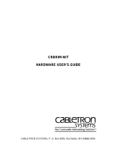
Step 3 Place the router so that the front panel is facing you. Remove the three screws located on top of the cover
near the front edge. (See Figure 5-1 or Figure 5-2.) Set the screws aside in a safe place.
Step 4 Lift the front edge of the cover until it clears the front of the chassis. (See Figure 5-1 or Figure 5-2.)
Step 5 Pull the cover toward you until the metal tabs on the rear edge separate from the chassis bottom. (See
Figure 5-1 or Figure 5-2.)
Step 6 Lift the cover until it is free from the chassis and set it aside.
When you are ready to replace the cover, see the “Replacing the Cover on a Cisco 3620 or Cisco 3640
Router” section on page 5-30.

5-3
Cisco 3600 Series Hardware Installation Guide
OL-2056-02
Chapter 5 Installing Memory in the Router
Accessing the Mainboard
Figure 5-1 Removing the Cisco 3620 Router Cover
Figure 5-2 Removing the Cisco 3640 Router Cover
Removing the Cisco 3631 Router Cover
Perform the following procedure to remove the chassis cover:
Step 1 Power OFF the router. However, to channel ESD voltages to ground, do not unplug the power cable.
H7241
Screw
PCMCIA
0
ACTIVE
READY
1
1
0
SYSTEM
CON
AUX
RPS
H7043
Screw
0
ACTIVE
READY
123
PCMCIA
1
0
SYSTEM
CON
AUX
RPS

5-4
Cisco 3600 Series Hardware Installation Guide
OL-2056-02
Chapter 5 Installing Memory in the Router
Accessing the Mainboard
Warning
Before opening the chassis, disconnect the telephone-network cables to avoid contact
with telephone-network voltages. To see translations of the various warnings that
appear in this publication, refer to the Regulatory Compliance and Safety Information
document that accompanied this device.
Step 2 Disconnect all network interface cables from the rear panel.
Step 3 Place the router on a flat surface. Remove the five screws located on top of the cover.
Step 4 Rotate the cover up to a 45-degree angle. (See Figure 5-3.)
Step 5 Slide the cover to the side until the tabs are free from the slots. (See Figure 5-3.)
Figure 5-3 Removing the Cisco 3631 Router Cover
1 Lift cover 2 Slide cover
62483
1
2

5-5
Cisco 3600 Series Hardware Installation Guide
OL-2056-02
Chapter 5 Installing Memory in the Router
Accessing the Mainboard
Removing the Cisco 3660 Mainboard Tray
Note In this publication, references to Cisco 3660 routers include both Cisco 3661 and Cisco 3662 models.
Use the following procedure to remove the mainboard tray:
Step 1 Power OFF the router. However, to channel ESD voltages to ground, do not unplug the power cable.
Warning
Before opening the chassis, disconnect the telephone-network cables to avoid contact with
telephone-network voltages. To see translations of the warnings that appear in this publication,
refer to the
Regulatory Compliance and Safety Information
document that accompanied this
device.
Step 2 Remove all network interface cables from the mainboard tray’s rear panel.
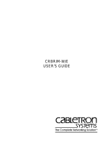
Step 3 Place the router so that the rear panel is facing you.
There are two sets of screws on the mainboard rear panel: one set of captive screws, and one set of Torx
screws. (See Figure 5-4.)
Caution Do not remove or loosen the Torx screws.
Step 4 Loosen the two captive screws located in the upper corners. (See part 1, Figure 5-4.)
Step 5 Swing the two tray levers out, and slide the mainboard tray out of the chassis. (See parts 2 and 3,
Figure 5-4.)

5-6
Cisco 3600 Series Hardware Installation Guide
OL-2056-02
Chapter 5 Installing Memory in the Router
Replacing DRAM and SDRAM
Figure 5-4 Removing the Cisco 3660 Mainboard Tray
Caution The mainboard is an ESD-sensitive component. To avoid damage, observe all ESD precautions.
When you are ready to replace the mainboard tray, see the “Replacing the Cisco 3660 Mainboard Tray”
section on page 5-33.
Replacing DRAM and SDRAM
Cisco 3600 series routers use two types of dynamic random access memory (DRAM):
• DRAM SIMMs (Used in Cisco 3620 and Cisco 3640 Routers), page 5-7
• SDRAM DIMMs Used in the Cisco 3631 and Cisco 3660 Router, page 5-14
Note SIMMs and DIMMs cannot be interchanged between the router models.
VCC OK
SYSTEM
FDX
LINK
100Mbps
FDX
1
0
LINK
100Mbps
ETH 0
ETH 3
ETHERNET
4E
ETH 2 ETH 1
123
ACT
LINK
0
CN/LP RXC
SERIAL 3 SERIAL 2
SERIAL 1 SERIAL 0
RXD TXC
TXD
CN/LP RXC RXD TXC TXD
CN/LP RXC RXD
TXC
TXD
CN/LP RXC RXD TXC TXD
EN
SERIAL
4T
VOICE
2V
V0
V1
EN
HIGH SPEED SERIAL
1HSSI
HS
TD
TC
RD
RC
LB/CN
SEE MANUAL BEFORE INSTALLATION
VIC
FXS
IN USE
IN USE
1
0
17335
Tray levers
1
22
3

5-7
Cisco 3600 Series Hardware Installation Guide
OL-2056-02
Chapter 5 Installing Memory in the Router
Replacing DRAM and SDRAM
DRAM SIMMs (Used in Cisco 3620 and Cisco 3640 Routers)
This section describes how to upgrade DRAM single in-line memory modules (SIMMs) in Cisco 3620
and Cisco 3640 routers. You might need to upgrade the DRAM SIMMs for the following reasons:
• You upgraded the Cisco IOS feature set or release and it requires additional DRAM.
• The router maintains large routing tables or other memory-intensive features, such as spoofing or
protocol translations.
The Cisco 3620 and Cisco 3640 routers each contain four 72-pin SIMM sockets (or banks) for DRAM.
Each socket can be filled with a single 32-bit-wide, 72-pin DRAM SIMM. You can configure DRAM as
a mixture of primary or main memory, which is reserved for the CPU, and shared memory, which is used
for data transmitted or received by modules and WAN interface cards.
To see how much memory is currently installed in the router, enter the show version command while the
router is in the privileged EXEC mode (Router# prompt). Near the middle of the resulting output, a
message similar to the following displays:
Cisco 3640(R4700) processor (revision 0x00) with 24576K/8192K bytes of memory.
This line shows how much memory is installed (in this example, 24576K/8192K). The first number
represents primary memory and the second number represents shared memory.
You can configure DRAM to be either 32 or 64 bits wide. To use 64-bit mode, you must install DRAM
SIMMs in pairs of the same size. Generally, basic software feature sets (such as IP) use 32-bit DRAM
SIMMs and robust software feature sets (such as Enterprise) use 64-bit DRAM SIMMs.
Note In the Cisco 3620 router, DRAM supports 32-bit operation only, whereas in the Cisco 3640 router,
DRAM supports either 32- or 64-bit operation.
Note In 32-bit mode, the router performs approximately 20 percent slower than when DRAM is configured
for 64-bit mode operation.
Each SIMM socket corresponds to one bank of memory. Fill banks consecutively with no gaps; start
filling banks from 0, and empty banks starting with 3. Bank 0 must always be filled first and emptied last.
Only certain combinations of DRAM SIMMs are permitted. These combinations are shown inTable 5-1
for 32-bit configurations used in Cisco 3620 routers, Table 5-2 for 32-bit configurations used in
Cisco 3640 routers, and Table 5-3 for 64-bit configurations used in Cisco 3640 routers.
Follow these rules to use 64-bit mode DRAM configuration:
• SIMMs in banks 0 and 1 must be the same size (in MB) and have the same access time (in
nanoseconds).
• SIMMs in banks 2 and 3 must also be the same size and have the same access time.
• SIMMs in banks 2 and 3 must be less than or equal to the size of the SIMMs in banks 0 and 1.
Figure 5-5 or Figure 5-6 shows the DRAM SIMM locations in your router.

5-8
Cisco 3600 Series Hardware Installation Guide
OL-2056-02
Chapter 5 Installing Memory in the Router
Replacing DRAM and SDRAM
Figure 5-5 DRAM SIMM Locations in the Cisco 3620 Router
Figure 5-6 DRAM SIMM Locations in the Cisco 3640 Router
H7317
DRAM SIMMs
0123
H7081
DRAM SIMMs
0123

5-9
Cisco 3600 Series Hardware Installation Guide
OL-2056-02
Chapter 5 Installing Memory in the Router
Replacing DRAM and SDRAM
Table 5-1 32-Bit DRAM Configuration for Cisco 3620 Routers
Bank 0
(SIMM 0)
Bank 1
(SIMM 1)
Bank 2
(SIMM 2)
Bank 3
(SIMM 3)
Total
Memory
4 MB 4 MB 4 MB 4 MB 16 MB
4 MB 4 MB 8 MB Not installed 16 MB
8 MB 8 MB Not installed Not installed 16 MB
16 MB Not installed Not installed Not installed 16 MB
4 MB 16 MB Not installed Not installed 20 MB
4 MB 4 MB 4 MB 4 MB 16 MB
8 MB 8 MB 4 MB Not installed 20 MB
16 MB 4 MB Not installed Not installed 20 MB
8 MB 16 MB Not installed Not installed 24 MB
8 MB 8 MB 8 MB Not installed 24 MB
8 MB 8 MB 4 MB 4 MB 24 MB
16 MB 8 MB Not installed Not installed 24 MB
8 MB 8 MB 4 MB 8 MB 28 MB
8 MB 8 MB 8 MB 4 MB 28 MB
8 MB 8 MB 16 MB Not installed 32 MB
8 MB 8 MB 8 MB 8 MB 32 MB
16 MB 16 MB Not installed Not installed 32 MB
16 MB 16 MB 4 MB Not installed 36 MB
16 MB 16 MB 4 MB 4 MB 40 MB
16 MB 16 MB 8 MB Not installed 40 MB
16 MB 16 MB 4 MB 8 MB 44 MB
16 MB 16 MB 8 MB 4 MB 44 MB
16 MB 16 MB 8 MB 8 MB 48 MB
16 MB 16 MB 16 MB Not installed 48 MB
16 MB 16 MB 16 MB 4 MB 52 MB
16 MB 16 MB 16 MB 8 MB 56 MB
16 MB 16 MB 16 MB 16 MB 64 MB

5-10
Cisco 3600 Series Hardware Installation Guide
OL-2056-02
Chapter 5 Installing Memory in the Router
Replacing DRAM and SDRAM
Table 5-2 32-Bit DRAM Configuration for Cisco 3640 Routers
Bank 0(SIMM
0)
Bank 1
(SIMM 1)
Bank 2
(SIMM 2)
Bank 3
(SIMM 3)
Total
Memory
4 MB 4 MB 8 MB Not installed 16 MB
16 MB Not installed Not installed Not installed 16 MB
4 MB 16 MB Not installed Not installed 20 MB
8 MB 8 MB 4 MB Not installed 20 MB
16 MB 4 MB Not installed Not installed 20 MB
8 MB 16 MB Not installed Not installed 24 MB
8 MB 8 MB 8 MB Not installed 24 MB
16 MB 8 MB Not installed Not installed 24 MB
8 MB 8 MB 4 MB 8 MB 28 MB
8 MB 8 MB 8 MB 4 MB 28 MB
8 MB 8 MB 16 MB Not installed 32 MB
16 MB 16 MB 4 MB Not installed 36 MB
16 MB 16 MB 8 MB Not installed 40 MB
16 MB 16 MB 8 MB 4 MB 44 MB
16 MB 16 MB 4 MB 8 MB 44 MB
16 MB 16 MB 16 MB 4 MB 52 MB
16 MB 16 MB 4 MB 16 MB 52 MB
16 MB 16 MB 16 MB 8 MB 56 MB
16 MB 16 MB 8 MB 16 MB 56 MB
Table 5-3 64-Bit DRAM Configuration for Cisco 3640 Routers
Bank 0
(SIMM 0)
Bank 1
(SIMM 1)
Bank 2
(SIMM 2)
Bank 3
(SIMM 3)
Total
Memory
4 MB 4 MB 4 MB 4 MB 16 MB
8 MB
1
8 MB Not installed Not installed 16 MB
8 MB-Dual
2
8 MB-Dual Not installed Not installed 16 MB
8 MB 8 MB 4 MB 4 MB 24 MB
8 MB-Dual 8 MB-Dual 4 MB 4 MB 24 MB
8 MB 8 MB 8 MB 8 MB 32 MB
8 MB 8 MB 8 MB-Dual 8 MB-Dual 32 MB
8 MB-Dual 8 MB-Dual 8 MB 8 MB 32 MB
8 MB-Dual 8 MB-Dual 8 MB-Dual 8 MB-Dual 32 MB
16 MB 16 MB – – 32 MB
16 MB 16 MB 4 MB 4 MB 40 MB
16 MB 16 MB 8 MB 8 MB 48 MB

5-11
Cisco 3600 Series Hardware Installation Guide
OL-2056-02
Chapter 5 Installing Memory in the Router
Replacing DRAM and SDRAM
DRAM SIMM Orientation
SIMMs have a polarization notch to ensure proper orientation and alignment holes to ensure proper
positioning. Figure 5-7 shows the polarization notch and alignment holes on a SIMM. DRAM SIMMs
are installed with the connector edge down and the polarization notch near the front of the chassis.
Caution To avoid damaging ESD-sensitive components, observe all ESD precautions. To avoid damaging the
underlying mainboard, do not use excessive force when you remove or replace SIMMs.
Figure 5-7 DRAM SIMM
16 MB 16 MB 8 MB-Dual 8 MB-Dual 48 MB
16 MB 16 MB 16 MB 16 MB 64 MB
32 MB-Dual
3
32 MB-Dual Not installed Not installed 64 MB
32 MB-Dual 32 MB-Dual 4 MB 4 MB 72 MB
32 MB-Dual 32 MB-Dual 8 MB 8 MB 80 MB
32 MB-Dual 32 MB-Dual 8 MB-Dual 8 MB-Dual 80 MB
32 MB-Dual 32 MB-Dual 16 MB 16 MB 96 MB
32 MB-Dual 32 MB-Dual 32 MB-Dual 32 MB-Dual 128 MB
1. 8 MB = single-bank SIMM, 8 MB in size.
2. 8 MB-Dual = dual-bank SIMM, 8 MB in size.
3. 32 MB-Dual = dual-bank SIMM, 32 MB in size.
Table 5-3 64-Bit DRAM Configuration for Cisco 3640 Routers (continued)
Bank 0
(SIMM 0)
Bank 1
(SIMM 1)
Bank 2
(SIMM 2)
Bank 3
(SIMM 3)
Total
Memory
Alignment holes
Connector edge
Polarization notch
H2407

5-12
Cisco 3600 Series Hardware Installation Guide
OL-2056-02
Chapter 5 Installing Memory in the Router
Replacing DRAM and SDRAM
Removing DRAM SIMMS
Perform this procedure to remove DRAM SIMMs:
Step 1 Attach an ESD-preventive wrist strap and ensure that it makes good contact with your skin. Connect the
equipment end of the wrist strap to the metal back plate of the chassis, avoiding contact with the
connectors.
Step 2 On the mainboard, locate the DRAM SIMM sockets shown in Figure 5-5 or Figure 5-6.
Caution Handle SIMMs by the non-connector edges only. SIMMs are ESD-sensitive components and can be
damaged by mishandling.
Step 3 Remove one SIMM at a time, beginning with the SIMM in bank 3. To lift the SIMM out of its socket,
pull the locking spring clips on both sides outward and tilt the SIMM toward the right side of the chassis,
until it is free of the clips. (See Figure 5-8.)
Figure 5-8 Removing DRAM SIMMs
Step 4 Hold the SIMM by the edges with your thumb and index finger and lift it out of the socket. Place the
removed SIMM in an antistatic bag to protect it from ESD damage.
Step 5 Repeat Step 3 and Step 4 for each SIMM.
2. Push the top of the
SIMM forward and down.
1. Pull the locking spring clips outward.
SIMM
polarization
notch
Top view
Front of chassis
H7038

5-13
Cisco 3600 Series Hardware Installation Guide
OL-2056-02
Chapter 5 Installing Memory in the Router
Replacing DRAM and SDRAM
Installing DRAM SIMMs
Perform this procedure to install DRAM SIMMs:
Step 1 Attach an ESD-preventive wrist strap and ensure that it makes good contact with your skin. Connect the
equipment end of the wrist strap to the metal back plate of the chassis, avoiding contact with the
connectors.
Step 2 On the mainboard, locate the DRAM SIMM sockets shown in Figure 5-5 or Figure 5-6.
Caution Handle SIMMs by the edges only. SIMMs are ESD-sensitive components and can be damaged by
mishandling.
Step 3 Hold the SIMM with the polarization notch on the right, near the front of the chassis, and with the
connector edge at the bottom.
Step 4 Beginning with bank 0, insert the SIMM into the socket at an angle, tilted toward the right side of the
chassis. Rock the SIMM into a vertical position (see Figure 5-9), using the minimum amount of force
required. When the SIMM is properly seated, the socket guide posts fit through the alignment holes, and
the locking spring clips click into place.
Step 5 Ensure that each SIMM is straight (perpendicular to the socket), and that the alignment holes (as shown
in Figure 5-9) line up with the plastic socket guides on the socket.
Figure 5-9 Installing DRAM SIMMs
Caution It is normal to feel some resistance when installing a SIMM, but do not use excessive force on the
SIMM, and do not touch the surface components.
Step 6 Repeat Step 3 through Step 5 for each SIMM.
When you finish replacing SIMMs, proceed to the “Replacing the Cover on a Cisco 3620 or Cisco 3640
Router” section on page 5-30.
H7037
1. Insert the SIMM into the socket
at an angle from vertical.
The socket guide posts fit through
the holes in the SIMM.
3.
The locking springs clip the back
of the SIMM.
4.
View from front of chassis
2. Push the top of the SIMM
down and back.

5-14
Cisco 3600 Series Hardware Installation Guide
OL-2056-02
Chapter 5 Installing Memory in the Router
Replacing DRAM and SDRAM
SDRAM DIMMs Used in the Cisco 3631 and Cisco 3660 Router
This section describes how to upgrade synchronous dynamic random access memory (SDRAM) dual
in-line memory modules (DIMMs) in the Cisco 3631 and Cisco 3660 routers. You might need to upgrade
the SDRAM DIMMs for the following reasons:
• You upgraded the Cisco IOS feature set or release and it requires additional SDRAM.
• The router maintains large routing tables or other memory-intensive features, such as spoofing or
protocol translations.
The Cisco 3631 and Cisco 3660 routers contain two 168-pin DIMM sockets for SDRAM. Each socket
can be filled with a single 64-bit-wide, 168-pin SDRAM DIMM. You can configure SDRAM as a
mixture main memory, which is reserved for the CPU, and shared memory, which is used for data
transmitted or received by modules and WAN interface cards. See Figure 5-10 and Figure 5-11 for
DIMM locations.
To see how much memory is currently installed in the router, enter the show version command while the
router is in the privileged EXEC mode (Router# prompt). Near the middle of the resulting output, a
message similar to the following displays:
Cisco 3660(R527x) processor (revision 0x00) with 24576K/8192K bytes of memory.
This line shows how much memory is installed (in this example, 24576K/8192K). The first number
represents primary memory and the second number represents shared memory. Your router supports up
to 256 MB of SDRAM.
Each DIMM socket corresponds to one bank of memory. Fill banks from 0, and empty banks starting
with 1. Bank 0 must always be filled first and emptied last.
The Cisco 3631 router supports both parity and non-parity PC-100 DIMMs ranging in capacity from
64 MB to 128 MB. Only certain combinations of SDRAM DIMMs are permitted. (See Table 5-5.)
The Cisco 3660 router supports both parity and non-parity PC-100 DIMMs ranging in capacity from
16 MB to 128 MB. Only certain combinations of SDRAM DIMMs are permitted. (See Table 5-5.)
Note An advantage of parity DIMMs over non-parity DIMMs is easier identification of memory errors; a
disadvantage is lower processing speed.
Note To use a 64-bit mode SDRAM configuration, the DIMM in bank 1 must be less than or equal to the
size of the DIMM in bank 0.

5-15
Cisco 3600 Series Hardware Installation Guide
OL-2056-02
Chapter 5 Installing Memory in the Router
Replacing DRAM and SDRAM
Figure 5-10 SDRAM DIMM Locations in the Cisco 3631 Router
Table 5-4 SDRAM Configurations for Cisco 3631 Routers
Bank 0 (SIMM 0) Bank 1 (SIMM 1) Total Memory
64 MB Not installed 64 MB
32 MB 32 MB 64 MB
32 MB 64 MB 96 MB
64 MB 32 MB 96 MB
128 MB Not installed 128 MB
64 MB 64 MB 128 MB
Not installed 128 MB 128 MB
32 MB 128 MB 160 MB
128 MB 32 MB 160 MB
64 MB 128 MB 192 MB
128 MB 64 MB 192 MB
128 MB 128 MB 256 MB
62578
0
1
SDRAM DIMMs

5-16
Cisco 3600 Series Hardware Installation Guide
OL-2056-02
Chapter 5 Installing Memory in the Router
Replacing DRAM and SDRAM
Figure 5-11 SDRAM DIMM Locations in the Cisco 3660 Router
Table 5-5 SDRAM Configurations for Cisco 3660 Routers
Bank 0 (SIMM 0) Bank 1 (SIMM 1) Total Memory
16 MB 16 MB 32 MB
32 MB Not installed 32 MB
32 MB 16 MB 48 MB
32 MB 32 MB 64 MB
64 MB Not installed 64 MB
64 MB 16 MB 80 MB
64 MB 32 MB 96 MB
64 MB 64 MB 128 MB
128 MB Not installed 128 MB
128 MB 16 MB 144 MB
128 MB 32 MB 160 MB
128 MB 64 MB 192 MB
128 MB 128 MB 256 MB
SDRAM DIMMs
17337
10

5-17
Cisco 3600 Series Hardware Installation Guide
OL-2056-02
Chapter 5 Installing Memory in the Router
Replacing DRAM and SDRAM
SDRAM DIMM Orientation
DIMMs have polarization notches to ensure proper orientation and alignment holes to ensure proper
positioning. Figure 5-12 shows the polarization notches and alignment holes on a DIMM.
Caution To avoid damaging ESD-sensitive components, observe all ESD precautions. To avoid damaging the
underlying mainboard, do not use excessive force when you remove or replace DIMMs.
Figure 5-12 SDRAM DIMM
Polarization notches
Connector edge
17338
Alignment holes

5-18
Cisco 3600 Series Hardware Installation Guide
OL-2056-02
Chapter 5 Installing Memory in the Router
Replacing DRAM and SDRAM
Removing SDRAM DIMMS
Perform this procedure to remove SDRAM DIMMs:
Step 1 Attach an ESD-preventive wrist strap and ensure that it makes good contact with your skin. Connect the
equipment end of the wrist strap to the metal back plate of the chassis, avoiding contact with the
connectors.
Step 2 On the mainboard, locate the SDRAM DIMM sockets shown in Figure 5-11.
Caution Handle DIMMs by the edges only. DIMMs are ESD-sensitive components and can be damaged by
mishandling.
Step 3 Remove the DIMM by pushing the locking spring clips on both sides outward. This ejects the DIMM
from its socket. (See Figure 5-13.)
Figure 5-13 Removing and Installing SDRAM DIMMs
Step 4 Hold the DIMM by the edges with your thumb and index finger and lift it out of the socket. Place the
removed DIMM in an antistatic bag to protect it from ESD damage.
Step 5 If necessary, repeat Step 3 and Step 4 for the other DIMM.
17943
2
2
1
Locking spring clips

5-19
Cisco 3600 Series Hardware Installation Guide
OL-2056-02
Chapter 5 Installing Memory in the Router
Replacing Flash Memory SIMMs
Installing SDRAM DIMMs
Perform this procedure to install SDRAM DIMMs:
Step 1 Attach an ESD-preventive wrist strap and ensure that it makes good contact with your skin. Connect the
equipment end of the wrist strap to the metal back plate of the chassis, avoiding contact with the
connectors.
Step 2 On the mainboard, locate the SDRAM DIMM sockets shown in Figure 5-11.
Caution Handle DIMMs by the non-connector edges only. DIMMs are ESD-sensitive components and can be
damaged by mishandling.
Step 3 Hold the DIMM with the polarization notch on the right, near the rear of the chassis, and with the
connector edge at the bottom.
Step 4 Beginning with socket 0, insert the DIMM perpendicular to the socket. Push firmly into place (see
Figure 5-13), using the minimum amount of force required. When the DIMM is properly seated, the
socket guide posts fit through the alignment holes, and the locking spring clips click into place.
Step 5 Ensure that each DIMM is straight (perpendicular to the socket). (See Figure 5-13.)
Caution It is normal to feel some resistance when installing a DIMM, but do not use excessive force on the
DIMM, and do not touch the surface components.
Step 6 Repeat Step 3 through Step 5 for each DIMM.
When you finish replacing DIMMs, and have installed all internal components, proceed to the
“Replacing the Cisco 3660 Mainboard Tray” section on page 5-33.
Replacing Flash Memory SIMMs
This section describes how to upgrade the Flash memory SIMMs. The system code (Cisco IOS software)
is stored in the Flash memory SIMMs. You might need to replace or add Flash memory SIMMs to
upgrade to a new Cisco IOS software feature set.
The router contains one or two 80-pin Flash memory SIMMs. You can upgrade Flash memory by
replacing the existing 4-MB SIMM with an 8- or 16-MB SIMM, or by adding a SIMM to the second
Flash memory socket. You can install from 4 to 32 MB of Flash memory. The size of the SIMMs in the
two Flash memory sockets need not be the same.
Note Flash memory SIMMs are not interchangeable with DRAM SIMMs (used in Cisco 3620 and
Cisco 3640 routers) or SDRAM DIMMs (used in Cisco 3631 and Cisco 3660 routers).
Each Flash memory SIMM socket corresponds to one bank of memory. Fill banks starting with 0, and
empty banks starting with 1. Bank 0 must always be filled first and emptied last.
Table 5-6 lists possible Flash memory SIMM configurations and the resulting total Flash memory.

5-20
Cisco 3600 Series Hardware Installation Guide
OL-2056-02
Chapter 5 Installing Memory in the Router
Replacing Flash Memory SIMMs
Flash memory SIMMs have a polarization notch to ensure proper orientation and alignment holes to
ensure proper positioning, similar to that shown in Figure 5-7. Flash memory SIMMs are installed with
the connector edge down and the polarization notch near the front of the chassis.
Caution To avoid damaging ESD-sensitive components, observe all ESD precautions. To avoid damaging the
underlying mainboard, do not use excessive force when you remove or replace SIMMs.
Figure 5-14, Figure 5-15, and Figure 5-16 show the location of the Flash memory SIMMs on your
router’s mainboard.
Table 5-6 Flash Memory SIMM Configurations
Bank 0 Bank 1 Total Memory
4 MB – 4 MB
4 MB 4 MB 8 MB
4 MB 8 MB 12 MB
4 MB 16 MB 20 MB
8 MB – 8 MB
8 MB 4 MB 12 MB
8 MB 8 MB 16 MB
8 MB 16 MB 24 MB
16 MB – 16 MB
16 MB 4 MB 20 MB
16 MB 8 MB 24 MB
16 MB 16 MB 32 MB
32 MB 32 MB 64 MB
1
1. The 64 MB configuration is only available on the
Cisco 3660 router.
/