Page is loading ...

CHAPTER
1-1
Cisco 12006 and Cisco 12406 Router Installation and Configuration Guide
OL-11497-03
1
Product Overview
This chapter provides an overview of the Cisco 12006 and Cisco 12406 series
routers. It contains physical descriptions of the router hardware and major
components, and functional descriptions of the hardware-related features.
Introduction
The routers described in this guide are part of the Cisco 12006 and Cisco 12406
series routers and include:
• The original Cisco 12006 and Cisco 12406 series routers.
• The Cisco 12006 and Cisco 12406 enhanced series routers. The enhanced
series of routers use higher capacity power supplies, a more powerful blower
module, and have a new front door.
Note Most illustrations are shown without the new front door for clarity.

Chapter 1 Product Overview
Product Description
1-2
Cisco 12006 and Cisco 12406 Router Installation and Configuration Guide
OL-11497-03
These two router models are differentiated by the switching capacity of the switch
fabric installed in the router:
• Cisco 12006 Router—2.5-Gbps switch fabric
• Cisco 12406 Router—10-Gbps switch fabric
Other than their various capacities, these routers are almost identical. Differences
between each router are described unless otherwise noted, all information in this
publication applies to all routers.
Product Description
The Cisco 12006 and Cisco 12406 routers, shown in Figure 1-1, are members of
the Cisco 12000 series router family. These routers are aimed at scaling the
Internet and enterprise backbones to speeds of 155 Mbps (OC-3/STM-1),
622 Mbps (OC-12/STM-4), 2.4 Gbps (OC-48/STM-16), and 10 Gbps
(OC-192/STM).

1-3
Cisco 12006 and Cisco 12406 Router Installation and Configuration Guide
OL-11497-03
Chapter 1 Product Overview
Product Description
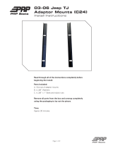
Figure 1-1 Cisco 12006 and Cisco 12406 router (Front View)
With a chassis height of 18.5 inches (46.9 cm), four Cisco 12006 and
Cisco 12406 routers can be installed in a single standard 7-foot (2.15-m)
equipment rack.
Cisco 12006 and Cisco 12406 routers support system software downloads for
most Cisco IOS software upgrades, which enables you to remotely download,
store, and boot from a new Cisco IOS image.
1 Line card slots (five) 5 Alarm card slots (two)
2 RP slot 6 Power module bays (two)
3 Blower module 7 CSC slots (two)
4 SFC slots (three) 8 Cable-management bracket
101344
S
L
O
T
-
0
GIGABIT ROUTE PROCESSOR
S
L
O
T
-
1
C
O
L
L
L
I
N
K
T
X
R
X
R
J
-
4
5
M
I
I
R
E
S
E
T
A
U
X
E
J
E
C
T
CONSOLE
C
ISC
O
12000
S
E
R
IE
S
G
IG
A
B
IT
S
W
IT
C
H
R
O
U
T
E
R
8 3
6
1 2
7
4
5

Chapter 1 Product Overview
Product Description
1-4
Cisco 12006 and Cisco 12406 Router Installation and Configuration Guide
OL-11497-03
Cisco 12006 and Cisco 12406 routers have the following key features:
• Route Processor (RP)—Slot 5 (bottom slot) is the recommended slot for the
first RP. When the router is equipped with a redundant RP, it can be installed
in any of the five regular line card slots.
• Line Cards—Up to five OC-192 line cards, four if redundant RPs are
installed. These slots support the online insertion and removal (OIR) feature
so installed cards are hot-swappable: A failed card can be removed and
replaced with the router powered on.
• Clock and Scheduler Cards (CSCs) and Switch Fabric Cards (SFCs)—Two
dedicated hot-swappable slots for CSCs; three dedicated hot-swappable slots
for SFCs.
Note The Cisco 12006 Router uses 2.5-Gbps switch fabric; the
Cisco 12406 Router uses 10-Gbps switch fabric. You cannot mix
2.5-Gbps switch fabric cards and 10-Gbps switch fabric cards in a
chassis. The router will not operate with a mix of switch fabric card
types.
Note When operating your router with a single CSC, the second CSC slot
must have a CSC blank filler (MAS-GSR6-CSCBLNK=) installed to
ensure EMI compliance.
• Two dedicated alarm card slots (for 1+1 redundancy)
• Alarm and Illumination—Alarm and illumination for operating ranges in the
card cage, clock and scheduler card, and switch fabric card bays.
• Two hot-swappable AC-input power supplies or DC-input power entry
modules (PEMs).
Note When operating your router on a single AC-input power supply or
DC-input PEM, the second power module bay must have a blank filler
(MAS-GSR-PWRBLANK=) installed to ensure EMI compliance.

1-5
Cisco 12006 and Cisco 12406 Router Installation and Configuration Guide
OL-11497-03
Chapter 1 Product Overview
Product Description
• All power modules and other field replaceable units (FRUs), except for the
air blower module and the power distribution unit (PDU), can be removed
from the front of the chassis.
• All source power connections are located at the rear of the chassis on the
PDU. (See Figure 1-2.)
• Enhanced models have a new stylish front door that hides router cabling. The
door can be installed to open from the right side or left side to give you total
flexibility.
• Network Equipment Building Systems—Cisco 12006 and Cisco 12406
routers comply with the Network Equipment Building System (NEBS)
Criteria Level 3 requirements defined in SR-3580 for flammability,
structural, and electronics compliance.
• Electromagnetic Compatibility and Electrostatic Discharge Compliant—
Cisco 12006 and Cisco 12406 routers comply with emissions, immunity, and
electrostatic discharge (ESD) standards for both product and packaging.
• Bonding and Grounding—Bonding and grounding for safety, circuit
protection, noise currents, reliability, and operations compliance.
• Environmental Monitoring—Cisco 12006 and Cisco 12406 router complies
with environmental monitoring standards for operating temperature and
humidity, as well as handling temperature and humidity (except for heat
dissipation).
• Shock and Vibration—Cisco 12006 and Cisco 12406 routers have been
shock- and vibration-tested for operating ranges, handling, and earthquake
standards to NEBS (Zone 4 per GR-63-Core). These tests have been
conducted in earthquake environment and criteria, office vibration and
criteria, transportation vibration and criteria, and packaged equipment shock
criteria.

Chapter 1 Product Overview
Product Description
1-6
Cisco 12006 and Cisco 12406 Router Installation and Configuration Guide
OL-11497-03
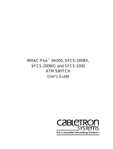
Figure 1-2 Cisco 12006 and Cisco 12406 router (Rear View)
•
Fiber Cable Management—Fiber cable management with support for
high-density fiber Fast Ethernet (FE) ports.
• Current 1.275-inch pitch line cards will fit in the line card cage with the
addition of a front panel adapter cover. The line card adapter cover is included
with the 1.275-inch line card.
1 Blower module 4 Air exhaust vents
2 Blower module LEDs 5 PDU (behind Blower module; AC
PDU shown)
3 Blower module handle – –
101114
HIGH SPEED BLOWER
3
4
1
2 5

1-7
Cisco 12006 and Cisco 12406 Router Installation and Configuration Guide
OL-11497-03
Chapter 1 Product Overview
Physical and Functional Description
Physical and Functional Description
The main physical components of Cisco 12006 and Cisco 12406 routers and their
functions are described in the following sections:
• Chassis, page 1-7
• Multigigabit Crossbar Switch Fabric, page 1-10
• Maintenance Bus, page 1-13
• Route Processors, page 1-15
• Line Cards, page 1-33
• Alarm Cards, page 1-35
• Power Subsystems, page 1-37
• Blower Module, page 1-47
• Air Filters, page 1-49
• Cable-Management System, page 1-50
Chassis
The Cisco 12006 and Cisco 12406 router chassis is an enclosure that consists of
two integral card cages and two power module bays. (see Figure 1-1.)
RP and Line Card Slots
The RP and line card cage has six user-configurable slots that support one RP and
up to five line cards. Network interfaces reside on the line cards that connect the
switch fabric of the router to the external networks. For more information about
the role of the RP, see the “Route Processors” section on page 1-15. For more
information about the role of the line cards, see the “Line Cards” section on
page 1-33.
Note Cisco 12006 and Cisco 12406 routers use line cards that are compatible with
other Cisco 12000 series routers.

Chapter 1 Product Overview
Chassis
1-8
Cisco 12006 and Cisco 12406 Router Installation and Configuration Guide
OL-11497-03
Switch Fabric Card Slots
The switch fabric circuitry resides in five fabric card slots: two for CSCs and three
for SFCs. (See Figure 1-1.) For more information about the role of the switch
fabric circuitry, see the “Multigigabit Crossbar Switch Fabric” section on
page 1-10.
Alarm Card Slots
Cisco 12006 and Cisco 12406 routers are equipped with two alarm cards. These
cards are positioned beside one another and occupy two card slots directly under
the CSC slots. (See Figure 1-1.) For more information about the role of the alarm
cards, see the “Alarm Cards” section on page 1-35.
Note The two alarm cards occupy slots under the two CSC slots in the CSC card cage,
but are not part of the switch fabric.
Chassis Backplane
All of the card cages are tied together electrically through a passive system
backplane in the back of the chassis. Nearly all of the wiring and circuitry in the
chassis is contained within or connected to the chassis backplane. The chassis
backplane distributes DC power to all of the cards in the chassis as well as the
blower module, and provides the physical communication pathway between
cards, both for network data and system communication across the internal system
maintenance bus (MBus).

1-9
Cisco 12006 and Cisco 12406 Router Installation and Configuration Guide
OL-11497-03
Chapter 1 Product Overview
Chassis
Power
Because a Cisco 12006 or Cisco 12406 Router can be configured with either an
AC-input power system or a DC-input power system, the power module bays will
accept either AC-input power supply modules or DC-input PEMs. For more
information about the power subsystems, see the “Power Subsystems” section on
page 1-37.
Caution To ensure that the chassis configuration complies with the required power
budgets, use the on-line power calculator. Failure to properly verify the
configuration may result in an unpredictable state if one of the power units fails.
Contact your local sales representative for assistance.
Cooling
Cisco 12006 and Cisco 12406 routers are equipped with a blower module to
distribute air within the chassis. The blower module is a removable module
located on the rear of the chassis. (See Figure 1-2.) For more information about
the blower module, see the “Blower Module” section on page 1-47.

Chapter 1 Product Overview
Multigigabit Crossbar Switch Fabric
1-10
Cisco 12006 and Cisco 12406 Router Installation and Configuration Guide
OL-11497-03
Multigigabit Crossbar Switch Fabric
Cisco 12006 and Cisco 12406 router switch fabric circuity provides synchronized
gigabit-speed interconnections for the line cards and the RP. The switch fabric
circuitry resides in five fabric card slots: two for CSCs; three for SFCs. (See
Figure 1-3.)
Figure 1-3 Clock and Scheduler and Switch Fabric Card Bays
Switch Fabric Card Types
The CSCs are installed in the half-width slots labeled CSC 0 and CSC 1 on the
lower left side of the chassis, located directly beneath the RP and line card cage
and directly above the alarm card bays. The three SFCs are installed in the
half-width slots labeled SFC 0, SFC 1, and SFC 2 on the lower right side of the
chassis.
Note To operate, Cisco 12006 and Cisco 12406 routers must have at least one CSC card
installed, in addition to SFC and alarm cards.
The CSC contains the following functionality:
SLOT-0
G
IG
A
B
IT
R
O
U
T
E
P
R
OC
E
SS
O
R
SLOT-1
COLL
LINK
TX
RX
RJ-45
MII
RESET
AUX
EJECT
CONSOLE
57084
SFC
CSC
CSC
SFC
SFC
Alarm
cards (2)
CISCO 12 000
SE
RIES
G
IG
A
B
IT
S
W
IT
C
H
R
O
U
T
E
R

1-11
Cisco 12006 and Cisco 12406 Router Installation and Configuration Guide
OL-11497-03
Chapter 1 Product Overview
Multigigabit Crossbar Switch Fabric
• System clock—The system clock synchronizes data transfers between line
cards or between the RP and a line card, through the switch fabric. In systems
with redundant CSCs, the two system clocks are synchronized so that if one
system clock fails, the other clock takes over. The system clock signal is sent
to all line cards, the RP, and switch fabric cards.
• Scheduler—The scheduler handles requests from the line cards for access to
the switch fabric. When the scheduler receives a request from a line card for
switch fabric access, the scheduler determines when to allow the line card
access to the switch fabric.
• Switch fabric—The switch fabric carries the user traffic between line cards or
between the RP and the line cards. The switch fabric card contains only the
switch fabric circuitry and receives scheduling information and system clock
information from the CSC.
The SFC contains only the switch fabric circuitry, which carries user traffic
between line cards or between the RP and the line cards. The SFC receives
scheduling information and the system clock sent from the CSC.
Nonredundant and Redundant System Configurations
Cisco 12006 and Cisco 12406 routers are available in two system configurations:
1. Nonredundant configuration that includes one CSC and one power supply.
When you order a Cisco 12006 or Cisco 12406 Router, the nonredundant
configuration is shipped by default.
2. Redundant configuration that includes two CSCs and two power supplies.
For the redundant configuration, EMI compliance and cooling requirements are
met by having two CSCs and two power supplies installed in the system.
For the nonredundant configuration, EMI compliance and cooling requirements
are met only when blank fillers are installed in place of either (or both) the second
(unused) CSC slot or the second (unused) power supply bay.
Note When operating your router with a single CSC, the second CSC slot must have a
CSC blank filler (MAS-GSR6-CSCBLNK=) installed to ensure EMI compliance.

Chapter 1 Product Overview
Multigigabit Crossbar Switch Fabric
1-12
Cisco 12006 and Cisco 12406 Router Installation and Configuration Guide
OL-11497-03
Switch Fabric Switching Capacity and Router Type
The Cisco 12006 Router is based on a 2.5-Gbps switch fabric, where each CSC or
SFC provides a 2.5-Gbps full-duplex connection to each line card in the system.
The 2.5-Gbps switch fabric consists of the 12006 Advanced Clock and Scheduler
Card (product number 12006-CSC=) and the 12006 Advanced Switch Fabric Card
(product number 12006-SFC=). The 2.5-Gbps switch fabric for the
Cisco 12006 Router can be identified by the Cisco identification labels on the
switch fabric cards (SFCs and CSCs): The CSC is labeled CSC-30/120 and the
SFC is labeled SFC-30/120.
The Cisco 12406 Router is based on a 10-Gbps switch fabric, where each CSC or
SFC provides a 10-Gbps full-duplex connection to each line card in the system.
The 10-Gbps switch fabric consists of the Clock and Scheduler Card (product
number GSR6-CSC=) and the Switch Fabric Card (product number GSR6-SFC=).
The 10-Gbps switch fabric cards are labeled simply CSC and SFC.
Note You cannot mix 2.5-Gbps switch fabric cards and 10-Gbps switch fabric cards in
a chassis. The router will not operate with a mix of switch fabric card types.
Switch Fabric Redundancy
Equipping the router with two CSCs provides data path, scheduler, and reference
clock redundancy. The interfaces between the line cards and the switch fabric are
monitored constantly. If the router detects a loss of synchronization (LOS), it
automatically activates the data paths of the redundant CSC, and data flows across
the redundant path. The switch to the redundant CSC occurs within 0.5 second,
with little or no loss of data.

1-13
Cisco 12006 and Cisco 12406 Router Installation and Configuration Guide
OL-11497-03
Chapter 1 Product Overview
Maintenance Bus
Maintenance Bus
The Cisco 12006 and Cisco 12406 router maintenance bus and MBus modules
manage the maintenance functions of the system. The MBus is integrated into the
backplane and consists of two separate buses, providing MBus redundancy.
Both MBus networks are linked to all the following items:
• Route processor and line cards
• CSCs, SFCs, and alarm cards
• Power modules
• Blower module
The MBus module located on each component communicates over the MBus and
is powered by DC voltage directly from the alarm card. The MBus performs the
functions of power-up/down control for each component, component (device)
discovery, code download, diagnostics, and environmental monitoring and
alarms.
Power-Up/Down Control
Each MBus module directly controls the DC-DC converters on the component on
which it is mounted, based on commands the component receives from its
on-board EPROM and from the RP. Each MBus module is tied directly to DC
voltage from the alarm card.
When power is applied to the router, all MBus modules immediately power up.
The MBus modules on the RP and CSC immediately turn on the DC-DC
converter, powering up the respective card. The line card MBus module waits to
power up the line card until it receives a command from the RP.
Device Discovery
The RP uses the MBus to detect the system configuration. The RP sends a
message over the MBus requesting identity information from all installed devices.
The responses provide component type, as well as slot numbers for the line cards,
CSCs, SFCs, and alarm cards.

Chapter 1 Product Overview
Maintenance Bus
1-14
Cisco 12006 and Cisco 12406 Router Installation and Configuration Guide
OL-11497-03
Code Download
A portion of the line card operating software can be downloaded from the RP to
the line card over the MBus. Because the MBus is relatively slow compared to the
switch fabric, only enough code is downloaded to the line card for it to access the
switch fabric and complete the download process.
Diagnostics
The diagnostic software image is downloaded from the RP to the line card during
the test sequence.
Environmental Monitoring and Alarms
The MBus module on each component monitors the environment of that
component as follows:
• Line cards and the RP are monitored for temperature by two temperature
sensors mounted on each card. The MBus module makes voltage adjustments
through software for the +2.5 VDC, +3.3 VDC, and +5 VDC DC-DC
converters.
• Clock and scheduler cards and switch fabric cards are monitored for
temperature by two temperature sensors mounted on each card. The MBus
module makes voltage adjustments through software for the +2.5 VDC and
+3.3 VDC converters.
• The MBus module on the alarm card makes voltage adjustments for +5 VDC.
• Environmental monitoring includes voltage monitoring, temperature
monitoring, and sensing for the blower module fans.

1-15
Cisco 12006 and Cisco 12406 Router Installation and Configuration Guide
OL-11497-03
Chapter 1 Product Overview
Route Processors
Route Processors
Each Cisco 12006 and Cisco 12406 router has one main system (or route)
processor. The route processor (RP) processes the network routing protocols and
distributes updates to the Cisco Express Forwarding (CEF) tables on the line
cards. The RP also performs general maintenance functions, such as diagnostics,
console support, and line card monitoring.
Route Processor Functions
The RP performs the following are primary functions:
• Downloading the Cisco IOS software to all of the installed line cards at
power-up
• Providing a console (terminal) port for router configuration
• Providing an auxiliary port for other external equipment, such as modems
• Providing an IEEE 802.3, 10/100-megabit-per-second (Mbps) Ethernet port
for Telnet functionality
• Running routing protocols
• Building and distributing routing tables to the line cards
• Providing general system maintenance functions for the router
The RP will function in any slot in the line card/RP card cage, but slot 5 is the
recommended slot. If the router is equipped with an optional, redundant route
processor, it can be installed in any of the remaining five slots.
The RP communicates with the line cards either through the switch fabric or
through the MBus. The switch fabric connection is the main data path for routing
table distribution as well as for packets that are sent between the line cards and
the RP. The MBus connection allows the RP to download a system bootstrap
image, collect or load diagnostic information, and perform general, internal
system maintenance operations.

Chapter 1 Product Overview
Route Processors
1-16
Cisco 12006 and Cisco 12406 Router Installation and Configuration Guide
OL-11497-03
Route Processor Types
Two types of RPs are available for Cisco 12006 and Cisco 12406 routers, the
Gigabit Route Processor (GRP), and the Performance Route Processor (PRP).
Each of these route processor types is reviewed in the following sections:
• Gigabit Route Processor, page 1-16
• Performance Route Processor, page 1-25
When not explicitly specified, this document uses the term route processor (RP)
to indicate either the GRP or the PRP.
Note If you install a second RP for redundancy, the second RP must be of the same type
as the primary RP.
Gigabit Route Processor
This section provides information about the GRP. The GRP front view is shown
in Figure 1-4.
Figure 1-4 Gigabit Route Processor (Front View)
The GRP card has the following components:
• RISC processor—IDT R5000 Reduced Instruction Set Computing (RISC)
processor used for the CPU. The CPU runs at an external bus clock speed of
100 MHz and an internal clock speed of 200 MHz.
• DRAM—Up to 512 megabytes (MB) of parity-protected, extended data
output (EDO) dynamic random-access memory (DRAM) on two
60-nanosecond (ns), dual in-line memory modules (DIMMs). 128 MB of
DRAM is the minimum shipping configuration for the GRP.
SLOT-0
GIGABIT ROUTE PROCESSOR
SLOT-1
COLL
LINK
TX
RX
RJ-45
MII
RESET
AUX
CONSOLE
EJECT
57074

1-17
Cisco 12006 and Cisco 12406 Router Installation and Configuration Guide
OL-11497-03
Chapter 1 Product Overview
Route Processors
Note GRP route memory configurations of 512 MB are compatible with
only Product Number GRP-B=. Cisco IOS Release 12.0(19)S or
12.0(19)ST or later, and ROMMON Release 11.2 (181) or later are
also required.
• SRAM—512 kilobytes (KB) of static random-access memory (SRAM) for
secondary CPU cache memory functions. SRAM is not user configurable or
field upgradeable.
• NVRAM—512 KB of nonvolatile RAM (NVRAM). NVRAM is not user
configurable or field upgradeable.
• Memory—Most of the additional memory components used by the system,
including onboard Flash memory and up to two Personal Computer Memory
Card International Association (PCMCIA)-based Flash memory cards and
Advanced Technology Attachment (ATA) Flash disks.
The GRP is shipped with 20 MB of Flash memory as the default
configuration.
• Sensors—Air-temperature sensors for environmental monitoring.
Note The GRP memory options and instructions for upgrading memory are described
in the Cisco 12000 Series Gigabit Switch Router Memory Replacement
Instructions (Document Number 78-4338-xx).
The Cisco IOS software images for operating the router reside in Flash memory
on the GRP. The Flash memory can be either the single in-line memory module
(SIMM) on the GRP or a PCMCIA Flash memory card that inserts into either
PCMCIA slot 0 or slot 1 (labeled SLOT-0 and SLOT-1) on the front of the GRP.
(See Figure 1-5.)
Note The GRP Flash memory SIMM contains the Cisco IOS software boot image, and
a PCMCIA Flash memory card contains the Cisco IOS software image.
Storing the Cisco IOS images in Flash memory enables you to download and boot
from upgraded Cisco IOS images remotely or from software images resident in
GRP Flash memory. The Cisco IOS software runs from within GRP DRAM.

Chapter 1 Product Overview
Route Processors
1-18
Cisco 12006 and Cisco 12406 Router Installation and Configuration Guide
OL-11497-03
Figure 1-5 GRP Layout
Backplane connector
S
L
O
T
-0
GIGABIT ROUTE PROCESSOR
S
LO
T
-1
C
O
LL
LIN
K
T
X
R
X
R
J-45
M
II
R
E
S
E
T
AUX
E
JE
C
T
H10547
Bank 2
DRAM DIMMs
Bank 1
PCMCIA slots
slot 0: bottom
slot 1: top
Console port
Ethernet
interface
(RJ-45 or MII)
Alphanumeric
LED displays
Auxiliary port
Flash
SIMM
U17
U42
U39

1-19
Cisco 12006 and Cisco 12406 Router Installation and Configuration Guide
OL-11497-03
Chapter 1 Product Overview
Route Processors
GRP Memory Components
Table 1-1 lists the memory components on the GRP. Figure 1-5 shows the location
of the DRAM and Flash SIMM on the GRP.
DRAM
The EDO DRAM on the GRP stores routing tables, protocols, and network
accounting applications, and runs the Cisco IOS software. The standard (default)
GRP DRAM configuration is 64 MB of EDO DRAM, which you can upgrade to
256 MB. Table 1-2 lists the DRAM configurations and upgrades.
Table 1-1 GRP Memory Components
Type Size Quantity Description Location
DRAM 128
1
or 256
MB
1. 128 MB of DRAM is the default DRAM configuration for the GRP.
1 or 2 64-MB or 128-MB DIMMs (based on
DRAM required) for main Cisco IOS
software functions
U39 (bank 1)
U42 (bank 2)
SRAM 512 KB
(fixed)
2
2. This memory is neither user configurable nor field upgradeable.
Secondary CPU cache memory functions —
NVRAM 512 KB
(fixed)
2
System configuration files, register
settings, and logs
—
Flash Memory 8 MB SIMM
3
3. SIMM socket is wired according to a Cisco design and does not accept industry-standard, 80-pin Flash SIMMs.
1 Cisco IOS software images and other
user-defined files
U17
20 MB
4
Flash
memory card
4. 20-MB Flash memory card is the default shipping configuration.
1 or 2 Cisco IOS software images, system
configuration files, and other user-defined
files on up to two Flash memory cars
5
5. Type I or Type II PCMCIA cards can be used in either PCMCIA slot.
Flash
memory card
slot 0 and
slot 1
Flash boot
ROM
512 KB 1 Flash EPROM for the ROM monitor
program boot image

Chapter 1 Product Overview
Route Processors
1-20
Cisco 12006 and Cisco 12406 Router Installation and Configuration Guide
OL-11497-03
Caution To prevent memory problems, DRAM DIMMs must be 3.3-volt (V),
60-nanosecond (ns) devices. Do not install other devices in the DIMM sockets.
Cisco recommends that you use the Cisco-approved memory options listed in
Table 1-2.
SRAM
SRAM provides secondary CPU cache memory. The standard GRP configuration
is 512 KB. Its principal function is to act as a staging area for routing table
updates and for information sent to and received from line cards. SRAM is not
user configurable and cannot be upgraded in the field.
NVRAM
NVRAM provides 512 KB of memory for system configuration files, software
register settings, and environmental monitoring logs. This information is backed
up with built-in lithium batteries that retain the contents for a minimum of five
years. NVRAM is not user configurable and cannot be upgraded in the field.
Flash Memory
Flash memory allows you to remotely load and store multiple Cisco IOS software
and microcode images. You can download a new image over the network or from
a local server and then add the new image to Flash memory or replace the existing
files. You then can boot the routers either manually or automatically from any of
the stored images.
Table 1-2 GRP DRAM Configurations
Total DRAM Product Numbers DRAM Sockets Number of DIMMs
128 MB
1
1. 128 MB is the standard (default) DRAM configuration for the GRP.
MEM-GRP/LC-64(=) U39 (bank 1) and
U42 (bank 2)
2 64-MB DIMMs
128 MB MEM-GRP/LC-128(=) U39 (bank 1) 1 128-MB DIMM
256 MB MEM-GRP/LC-256(=) U39 (bank 1) and
U42 (bank 2)
2 128-MB DIMMs
/