Page is loading ...

PN: 65-2025M | Rev. B
This Operation and Service Manual includes
sections for optional components that may or may
not be included in your system.
Your system may contain built-in accessory
instruments from other manufacturers. Please
refer to the original manufacturer’s instructions for
operation and maintenance of those instruments.
Advanced Dental Systems® & Advanced Endodontic Systems®
Online: www.asimedical.net | Main: (303) 766-3646 | Toll Free: (800) 566-9953
Triton™
Advanced Dental System®
Operation & Service Manual
Dental Operative Unit
Models: 2025M | 2025M/DV | 2025M/AR

ASI – The leader in Advanced Systems Integration | www.asimedical.net
TRITON™ ADVANCED DENTAL SYSTEMS®
2025M | 2025M/DV | 2025M/AR
2
65-2025M Rev. B
1.0 PRODUCT DESCRIPTION, INSTALLATION, AND SAFETY PRECAUTIONS ....................................4
1.1 Symbols ..............................................................................................................................4
1.2 General Safety Precautions .....................................................................................................4
1.3 Indications for Use, Product Description, and Theory of Operation ...................................................5
1.4 Unpacking ......................................................................................................................... 11
1.5 Dual Voltage Conversion ...................................................................................................... 13
1.6 Quick Start-Up List ............................................................................................................... 14
1.7 Dimensional Specifications, Capacities and Technical Data .......................................................... 16
1.8 Operating Environment and Classification of Equipment ............................................................... 17
2.0 COMPONENT OPERATING INSTRUCTIONS .........................................................................22
2.1 Closed Water System. .........................................................................................................22
2.2 Air/Water Syringe ..............................................................................................................22
2.3 Handpiece Connections & Fiber Optics Operation ..................................................................... 23
2.4 Handpiece Operation ..........................................................................................................25
2.5 Other Installed Instruments ..................................................................................................... 26
2.6 Oral Evacuation System (Optional) ..........................................................................................27
2.7 Self-Contained Vacuum Pump ................................................................................................27
3.0 MAINTENANCE ................................................................................................................28
3.1 Equipment Care and Inspection ..............................................................................................28
3.2 Cleaning, Disinfection & Sterilization .......................................................................................28
3.3 Self-Contained Models .........................................................................................................30
4.0 STORAGE AND SHIPPING ..................................................................................................32
4.1 Prepare for Storage .............................................................................................................32
4.2 Shipping Preparation ........................................................................................................... 32
5.0 LIMITED WARRANTY REV 0907 .........................................................................................33
5.1 Specific Warranty Modifications ............................................................................................33
5.2 Specific Warranty Modifications for Self-Contained Systems .........................................................33
5.3 Specific Supplemental Electronic Instrument Warranty..................................................................34
5.4 Replacement Parts Limited Warranty REV 0806 .........................................................................34
6.0 TROUBLESHOOTING .........................................................................................................35
6.1 Basic Troubleshooting Guide .................................................................................................35
6.2 Troubleshooting the Delivery Unit ............................................................................................35
7. 0 S E R V I C E ...........................................................................................................................42
7.1 Customer Support ............................................................................................................... 42
7.2 Replacement Parts ............................................................................................................... 42
7.3 Repairing an Air/Water and Air Only Syringe ........................................................................... 42
7.4 Servicing the Foot Control ..................................................................................................... 43
7.5 Opening Cover to Delivery System .........................................................................................43
7.6 Adjusting Handpiece Pressure ................................................................................................44
7.7 Opening Back Panel ............................................................................................................44
7.8 Servicing or Replacement of Air Compressor (85-0001) ..............................................................44

ASI – The leader in Advanced Systems Integration | www.asimedical.net
TRITON™ ADVANCED DENTAL SYSTEMS®
2025M | 2025M/DV | 2025M/AR
3
65-2025M Rev. B
7.9 Replacing the Vacuum Pump .................................................................................................. 47
7.10 Replacing Tubing in Purge Pump ............................................................................................. 47
7.11 Replacing the Water Relay ...................................................................................................48
7.12 Replacing Bulkhead Connector .............................................................................................48
7.13 Replacing Pucks in Control Block ...........................................................................................49
7.14 Fiber Optics & Instruments .....................................................................................................50
7.15 Closed Water System ......................................................................................................... 52
7.16 Compressed Air System ........................................................................................................53
7.71 Vacuum System ...................................................................................................................55
8.0 SCHEMATICS ....................................................................................................................57
8.1 Schematic, Delivery System Tubing ..........................................................................................57
8.2 Schematic, Control Block Diagram ..........................................................................................58
8.3 Schematic, Electrical 115V~ 60Hz Voltage Selected ..................................................................59
8.4 Schematic, Electrical 230V~ 50Hz Voltage Selected .................................................................. 60
8.5 Schematic, Electrical Wiring of Delivery System (Upper Compartment) ............................................ 61
8.6 Schematic, Electrical Wiring – Compressor & Vacuum Utilities (Lower Compartment) .......................... 62
8.7 Schematic, Pressure Switch – Air Compressor (Lower Compartment) ...............................................63
9.0 ILLUSTRATED PARTS LIST .....................................................................................................64
9.1 Delivery System ..................................................................................................................64
9.2 Delivery Instrument Components .............................................................................................66
9.3 Air/Water Syringe (PN 20-0008) ..........................................................................................68
9.4 Closed Water System (PN 80-0215) ....................................................................................... 70
9.5 Delivery System Rear View ....................................................................................................72
9.6 Cart System ....................................................................................................................... 74
9.7 Air Compressor, Complete Assembly (PN 85-0001) ................................................................... 76
9.8 Air Compressor, Main Component (PN 40-0019) ......................................................................78
9.9 Vacuum Pump, Complete Assembly (PN 85-0002) ..................................................................... 80
9.10 Vacuum Pump, Main Component (PN 40-0020) ....................................................................... 82
9.11 Air Tank, Dual Bracketed Complete Assembly (PN 80-0192) ........................................................ 84
9.12 Sediment Separator and Holding Tank (PN 80-0188 ..................................................................86
9.13 Purge Pump (PN 80-0214) ....................................................................................................87
9.14 Foot Control, Wet/Dry (PN 80-0112) ......................................................................................88
9.15 Satelec/Acteon Ultrasonic ..................................................................................................... 90
9.16 KaVo ................................................................................................................................ 91
9.15 Service Parts Kit (PN 95-0107) ...............................................................................................92
9.16 Cross Reference Parts List ...................................................................................................... 94
10.0 REFERENCE LISTS ...............................................................................................................98
10.1 Delivery System Preventative Maintenance Schedule ...................................................................98

ASI – The leader in Advanced Systems Integration | www.asimedical.net
TRITON™ ADVANCED DENTAL SYSTEMS®
2025M | 2025M/DV | 2025M/AR
4
65-2025M Rev. B
1.0 SAFETY, PRODUCT DESCRIPTION & INSTALLATION
1.1 Symbols
Important information for users and technicians
Action Required
Warning Symbol
Description of Danger Levels
CAUTION
CAUTION – Indicates a hazardous situation that can lead to property damage or minor to moderate injury.
WARNING
WARNING – Indicates a hazardous situation that can lead to serious injury or death.
DANGER
DANGER indicates a maximum hazardous situation that can directly cause serious injury or death.
1.2 General Safety Precautions
In addition to observing the normal precautions associated with standard dental practices and procedures, the following
precautions should be strictly noted and observed during the set-up, operation and maintenance of this system.
WARNING – Compressed Air
The compressed air system that operates this unit is under pressure. Compressed air can propel dust or loose particles
and can cause bodily injury or damage. Always turn the system off and bleed off air pressure before attaching or removing air
lines or accessories or servicing this unit. All air lines should be periodically inspected and replaced if worn or damaged.
If an outside compressed air supply is used to power this unit, the air supply must be regulated to 80 psi or below. Excessive
air pressure could cause certain components to rupture.
WARNING – Electrical Voltage
This system is powered by high voltage electricity. Like any other electrically powered device, if it is not used properly,
it can cause electrical shock. Always plug the power cord into an electrical outlet with adequate fuse protection and proper
grounding. In the event of a short circuit, grounding reduces the risk of shock by providing an escape wire for the electric
current. Improper grounding of the unit can result in a risk of electric shock. Always unplug the unit before doing any service or
repair to the unit.
WARNING – Presence of Heavy Metals/Amalgam
This cart may be equipped with optional suction instruments. As part of dental procedures, particles of amalgam may
be suctioned into the dental suction handpieces and collected within the system and trap filter.
WARNING – Infectious Materials
Infectious disease workplace safety protocols to safeguard against cross contamination of infectious disease should
always observed. When maintaining the suction system or emptying the contents of the suction waste container, safe
precautions and practices including the wearing of face mask, eye protection and gloves are to be followed.

ASI – The leader in Advanced Systems Integration | www.asimedical.net
TRITON™ ADVANCED DENTAL SYSTEMS®
2025M | 2025M/DV | 2025M/AR
5
65-2025M Rev. B
CAUTION – Correct Operating Voltage
Check the correct operating voltage on the rating plate and ensure that the product is correctly configured for the
voltage before plugging in and energizing.
WARNING – Qualified Personnel Only Should Operate This Device.
The Product should only be operated by qualified personnel only. The operator bears responsibility for the correct
settings and proper use of the system. ASI Medical, Inc. (ASI) cannot be held liable for any malfunction of this product, or
performance failure and/or its designed or desired utility, nor can ASI be held liable for injuries to persons or animals, in any
case when the device is misused or not operated, applied or maintained in strict accordance with user/owner instructions set
out in the operation manual. In the event of any doubt or question, the user is to contact ASI for clarification or assistance.
CAUTION – Damage From Unsuitable Accessories
Responsibility for the use of accessories, parts or assemblies from other manufacturers rest solely with the user.
WARNING – Electromagnetic Compatibility (EMC)
Changes or modifications to this product not expressly approved by the manufacturer may result in increased emissions
or decreased immunity performance of the product and could cause EMC issues with this or other equipment. This product
is designed and tested to comply with applicable regulation regarding EMC and shall be installed and put into service
according to the EMC information stated below:
WARNING
Use of portable phones or other portable or mobile radio frequency (RF) emitting equipment near the product may
cause unexpected or adverse operation.
WARNING
The use of accessories, transducers and cables other than those supplied may result in increased emissions or
decreased immunity performance of the product. The product shall not be used adjacent to, or stacked with, other equipment.
If adjacent or stacked use is necessary, the user shall be responsible to test to verify normal operation in the configuration in
which it is being used.
1.3 Indications for Use, Product Description & Theory of Operation
INDICATIONS FOR USE
The ASI Triton™ Advanced Dental System® is a self-contained dental treatment unit that contains a built-in water supply,
air compressor and vacuum system. It is designed to provide air, water, vacuum and electricity to operate various dental
handpieces, accessories and attachments and to serve as a base for other dental devices and accessories.
The device is intended for use to provide general dental restorative care and hygiene procedures in both traditional dental
office settings and/or mobile applications by or under the supervision of a licensed dentist or a hygienist if permitted by
applicable law.
PRODUCT DESCRIPTION
The Dental System product is a cart-based operative dental treatment unit requiring connection to an AC electrical power
supply. The product is constructed of aluminum chassis with powder coat paint finish, high grade dual wheel type casters
and composite work surface top. The product is hard wired with the appropriate type mains plug provided for the electrical
specification Model as listed.

ASI – The leader in Advanced Systems Integration | www.asimedical.net
TRITON™ ADVANCED DENTAL SYSTEMS®
2025M | 2025M/DV | 2025M/AR
6
65-2025M Rev. B
The system functions to operate dental handpieces and to serve as an integrated base for other dental devices and accessories.
Use of the system is intended only to support dental treatment and hygiene procedures, and operation of dental instruments by or
under the supervision of a licensed dentist. All model configurations include two fiber optic highspeed connections, one lowspeed
connection, air/water syringe, low pressure air-only syringe and water supply with two 1-Liter bottles.
The Triton™ Series is available with different configurations for various deployable options.
• 2025M–Includesfullstandard2025self-containedsystemwiththeadditionoftheshippingcase,handpiecebag
set, repair kit, upgrade to 4” locking casters and grounding strap. This model is for use with 120volt/60Hz only.
• 2025M/DV–Includesallfeaturesof2025MaboveplusspecialHERMmountsontheaircompressorandvacuum
pump for added durability during transport and with dual voltage power input capability. The dual voltage capability
allows the system to be operated either from a 120volt/60Hz input or 120volt/50Hz input.
• 2025M/AR–Includesallfeaturesofthe2025M/DVabove,plusapowerconditioner,KaVoelectricmotor
handpiece, piezo ultrasonic handpiece, Valo curing light and accessory handpieces as listed below and shown on
next page:
Part Number Description Qty
90 -5138 KaVo E25L Contra Angle 4
90-5144 KaVo 68LH Latch Head 8
90-5147 KaVo 10LP Straight Attachment 2
90-5148 NSK NL9000s Highspeed Handpiece 4
90-5150 KaVo 181L Air Motor 4
90-5151 NSK NL10Ti 6-Pin Coupler 1
90-5282 KaVo 7LP attachment 4
Part Number Description Qty
90 - 5414/A Satelec Ultrasonic Handpiece 4
90-5714 NSK Pana Spray 1
90-5714/N NSK Highspeed Nozzle 1
90-5715 KaVo Spray 6-Pack 1
90-5715/N KaVo Quick Nozzle 1
90-5715/N2 KaVo MULTIFlex Nozzle 1
2025M Back With Shipping Case
Repair Kit & Manual
Power Conditioner

ASI – The leader in Advanced Systems Integration | www.asimedical.net
TRITON™ ADVANCED DENTAL SYSTEMS®
2025M | 2025M/DV | 2025M/AR
7
65-2025M Rev. B
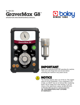
TRITON-AR MILITARY HANDPIECE KIT 90-2025M/AR – See Handpiece Setup 1.4.1 for guidance on handpiece connections
Weight: 9lbs, Dimensions: 14 1/2” x 13” x 4 1/2”
KaVo 25LCR Highspeed
Contra Angle
Ratio 1:5
ASI PN: 90-5138
Qty: 4
KaVo 10LP Straight
Lowspeed
Ratio 1:1
ASI PN: 90-5147
Qty: 2
Acteon/Satelec Ultrasonic
Handpiece - Piezo
ASI PN: 90-5414/A
Qty: 4
NSK PANA Spray Lubricant Oil
ASI PN: 90-5714
Qty: 1
KaVo Spray
ASI PN: 90-5715
Qty: 1 box of 6
KaVo Quick Nozzle
ASI PN: 90-5715/N
Qty: 1
KaVo MULTIflex Nozzle
ASI PN: 90-5715/N2
Qty: 1
Spray Nozzle –
PANA Spray
ASI PN: 90-5714N
Qty: 1
KaVo 7LP Lowspeed for
Removable Attachments
Ratio 2.7:1
ASI PN: 90-5282
Qty: 4
KaVo 181L IntraLux Air Motor
ASI PN: 90-5150
Qty: 4
KaVo 68LH Latch Head 1:1
ASI PN: 90-5144
Qty: 8
NSK-X600L Highspeed
Handpiece
ASI PN: 90-5148
Qty: 4
NSK-NL10Ti Titanium Coupler
6-Pin
ASI PN: 90 -5151
Qty: 1

ASI – The leader in Advanced Systems Integration | www.asimedical.net
TRITON™ ADVANCED DENTAL SYSTEMS®
2025M | 2025M/DV | 2025M/AR
8
65-2025M Rev. B
THEORY OF OPERATION
The Advanced Delivery System is a pneumatically controlled system that uses standard compressed air for operation of dental
tools and accessories and for pressurizing a closed water supply. The system uses air pressure from a foot control to operate
air driven tools and also to provide a signal to turn electric instruments on and off. This pneumatic control capability provides
flexibility in that additional instruments can be included on the system for operation from the same foot control as described
below:
Handpiece Control and Operation
The system utilizes common dental industry type technology for selection and
activation of air driven drills and instruments via a five (5) position control block. The
block contains individual gasket diaphragms that are held in the closed position by
compressed air supplied by the handpiece holders. When a dental handpiece is
removed from its holder, the compressed air is relieved off the gasket diaphragms
for that particular instrument thereby allowing compressed air and water to flow to
the handpiece when the foot control is depressed. The flow rate of this compressed
air is controlled by individual stems on the top of the block and the flow of water by
individual needle valves with knobs located on the front and side of the unit.
Electric instruments such as the ultrasonic handpiece and electric motor are controlled via the same control block. However the
compressed air that flows from the block is routed to an air/electric switch that uses an air driven piston to close contacts when
activated to thereby send an electric signal for the ultrasonic and electric motor to operate. When the foot control is released,
these instruments will then turn off.
The System uses an air driven poppet style foot control valve that when depressed will send
compressed air to the control block to operate whichever handpiece is removed from its holder. The
foot control also features a toggle valve for selecting water to spray from the handpieces. When the
toggle is activated and the foot control is depressed, it will allow an air signal to travel through the
foot control tubing to open a water relay valve allowing water to flow to the selected handpiece.
When the foot control is released it will exhaust off the air to the water relay valve and allow it to
shut.
Closed Water System
The Closed water system uses two one liter plastic bottles designed for holding pressure.
The bottles can be filled with clean tap or distilled water for the source of water supply to
the dental handpieces and air/water syringe. The system works by supplying regulated
compressed air which pressurizes the water within the bottle and forces it up through the
pick up tubing in the bottle.

ASI – The leader in Advanced Systems Integration | www.asimedical.net
TRITON™ ADVANCED DENTAL SYSTEMS®
2025M | 2025M/DV | 2025M/AR
9
65-2025M Rev. B
Compressed Air System
The ASI compressed air system is designed to deliver oil-free air to run handpieces. The compressed air system is ideal for
mobile dental systems due to the small footprint, oil-less design, quiet sound level and airflow output that it provides.
Air Compressor
A motor drives a two stage piston design. Air is drawn into the first piston chamber
where it is initially compressed and then sent into the second piston chamber
where it is compressed further. A pressure switch controls the operation of the
compressor that turns it on and off.
Due to the oil-less design the compressor requires no lubrication and no
maintenance.
The pistons are dynamically balanced to high tolerances that enable a smooth running and quiet design.
The portable dental air compressor is controlled by an air pressure switch that senses when the pressure drops in the air tank to
activate the motor and then once air consumption ceases, it will sense when the air pressure has reached a pre-set point and
then will turn off the motor. This keeps the motor from running when the system is not in use.
The air compressor is mounted on special spring type isolators that allow it to float and thereby reduce vibration to the chassis.
A proprietary multi-stage intake muffler design attenuates and muffles sound waves to dampen sound.
Air Tanks and Dry, Clean Air
The Triton™ system uses a special two stage air tank design to remove condensation from the air
stream. The tanks are constructed of non-corroding aluminum that are lightweight. The dual air tank
design utilizes an in-line air regulator and moisture separator. Compressed air is sent to the first tank
and then the air stream is sent through the regulator where it is regulated down. Decompressing the
air cools the air and allows condensation to drop out of the air stream to assist in drying air. The
regulator has an automatic float bowl design that will lift whenever the system is fully depressurized
and allow moisture droplets to escape.
Dental Suction System
The ASI dental suction system is designed to provide suction to perform dental procedures.
Vacuum Pump
A motor drives a two headed oil-less piston pump.
The pistons require no lubrication and maintenance due to their oil-less design. The
pistons are dynamically balanced to high tolerances that enable a smooth running and
quiet design.

ASI – The leader in Advanced Systems Integration | www.asimedical.net
TRITON™ ADVANCED DENTAL SYSTEMS®
2025M | 2025M/DV | 2025M/AR
10
65-2025M Rev. B
Sediment Separator and Holding Tank
Equally Important to the suction design of mobile dental equipment is how the liquid contents
are handled. The suction system has a holding tank to provide capacity for a normal day of
procedures and is able to handle caustic chemicals and can be purged and cleaned at the end
of the day.
The system separates the air stream from the liquid and provides a sediment bowl that can be
removed.
Built into the top of the holding tank is a float switch to prevent over filling of the canister. Once
the liquid rises to a pre-set level, the float switch will cut off the power to the vacuum pump.
Purge System
The system uses an electric purge pump that can be turned on that will siphon the liquid from the holding
tank and empty out though the purge hose at the back of the system. At the end of the day’s procedures
the purge hose can be placed into a sink drain or quick connected to a sink’s P-trap and then the pump
turned on to purge the tank. Once complete, water with evacuation cleanser can be suctioned up
through the HVE and saliva ejector to rinse the tubes and the holding tank.
The pump squeezes the specially designed tubing to pull and push contents through the tube. This
pump design allows it to pull granular or sticky paste-like materials.

ASI – The leader in Advanced Systems Integration | www.asimedical.net
TRITON™ ADVANCED DENTAL SYSTEMS®
2025M | 2025M/DV | 2025M/AR
11
65-2025M Rev. B
1.4 Unpacking
The cart is contained in a hardened transport case. The case is heavy and requires two or more people to unpack.
1 – Lay case flat and remove
lid by releasing the
latches on all four sides.
2 – Stand the case up so
that wheels are on the
ground; unfold ramp.
3 – Remove foam on top of
cart.
4 – Locate foot pedal on
bottom of case; set aside,
making sure that it is out
of the way of the cart as
it is rolled out of the case.
5 – Carefully grasp tubings
and handpiece holder
bag while removing cart;
Two people are required.
6 – Prepare to place
handpieces in holders;
remove foot pedal from
bag and place on the
floor beside the cart.
7 – Unroll handpiece holder
bag, but be careful
so as not to drop any
handpieces.
8 – Lift handpiece holders so
they are facing upwards.
Ensure levers on right
side of holder is pointing
down toward the floor.
8 – Place handpieces in their
holders; tubings should
not be twisted.
Note: Handpiece holders are
labeled to help determine
which handpieces are to
go into which holders.
See next page for
handpiece setup info.
Units shown are sample configurations.
Your unit may vary slightly from the
ones pictured here.

ASI – The leader in Advanced Systems Integration | www.asimedical.net
TRITON™ ADVANCED DENTAL SYSTEMS®
2025M | 2025M/DV | 2025M/AR
12
65-2025M Rev. B
KaVo 25LCR
KaVo Motor
KaVo 18L
NSK
NL10Ti
NSK
NL9000
Electric Highspeed
KaVo 7LP
KaVo 68LH
KaVo 10LP
Air Lowspeed (Optional)
Ultrasonic
Air/Water Syringe
Saliva Ejector
Curing Light
High Volume Evacuator
Fiber Optic
Air Highspeed
Fiber Optic
Air Highspeed/Lowspeed
TO CART
1.4.1 Handpiece Setup

ASI – The leader in Advanced Systems Integration | www.asimedical.net
TRITON™ ADVANCED DENTAL SYSTEMS®
2025M | 2025M/DV | 2025M/AR
13
65-2025M Rev. B
Verify Mechanical Integrity and Safe Use
After unpacking the unit, look for any damage that could affect safe and proper operation. Ensure there are no missing parts
or accessories. Carefully inspect components for tightness and the absence of cracks, excessive wear or frayed electrical
cords. If there is any adverse damage or the lack of mechanical integrity that would prevent the safe use or operation of the
system, it should not be used until repair or replacements correcting the defects are made.
1.5 Dual Voltage Conversion
IMPORTANT NOTE: This system is capable of operation from either a
120volt/60 Hz or a 230volt/50 Hz power source.
CAUTION: All selector switches must be properly selected for the correct
voltage and frequency input for proper operation and to prevent damage to
electrical components.
NOTE: The cart system has three selector switches and an optional fourth switch
if equipped with a KaVo electric motor. Two voltage selectors are located on top
plate, and the other two where the power cord enters the cart at the back of the
cart.
Step 1: Ensure cart is unplugged from the power source. Worktop is held in place
with commercial grade Velcro. Carefully remove top – note that Velcro is very
strong and will require a firm grasp.
Step 2: Locate the voltage switch located at the rear of the top panel and select
either “230V” for 230V/50 Hz or “115V” for 120V/60 Hz. Use a small flat
screwdriver to select the desired voltage
Step 3: If the cart is equipped with a KaVo brand Electric Motor, it will be
necessary to switch it to the correct voltage as well. Locate the Voltage Selector
Switch Located at the right side of the top panel. Use a small flat screwdriver to
select the desired voltage.
Step 4. Locate the power cord inlet plate on the back of the cart. Remove the plate
by removing the two screws. Flip both of the voltage selectors on the back of the
cart to the desired voltage. Replace the power inlet plate.
Step 5. Replace the power cord plug with the correct type if necessary. The cart has been supplied with both a 115 Volt
NEMA type U.S. plug and Schuko 230 Volt European type Plug.
STEP 2
STEP 3
STEP 4

ASI – The leader in Advanced Systems Integration | www.asimedical.net
TRITON™ ADVANCED DENTAL SYSTEMS®
2025M | 2025M/DV | 2025M/AR
14
65-2025M Rev. B
1.6 Quick Start-Up List
The operator is expected to fully read and understand all aspects of the operation manual for operation of this dental system.
The following is a brief condensed highlight of steps to use the system.
Verify Mechanical Integrity and Safe Use – After unpacking the unit, look for any damage that could affect safe and proper
operation. Ensure there are no missing parts or accessories. Carefully inspect components for tightness and the absence of
cracks, excessive wear or frayed electrical cords. If there is any adverse damage or the lack of mechanical integrity that
would prevent the safe use or operation of the system, it should not be used until repair or replacements correcting the defects
are made.
Verify Handpiece Placements – Ensure all handpieces are placed into their correct holders and that the corresponding
tubing is correctly situated. This system uses auto holders that activate the instrument once it is removed. If any instruments
are incorrectly placed into holders, the selected instrument by the operator will fail to work. Quick Check – Verify all tubings
hanging straight down are not crossed and are placed in sequential order from left to right on the holder bar. This will ensure
they are placed correctly.
Verify Holder Switches are Active – The auto handpiece holders feature a lock out switch levers which can be used to disable
function of that instrument if desired by the operator. Ensure all these levers are pointing straight down towards the floor to
ensure all holders are set to active. Otherwise an instrument may fail to operate when removed from the holder.
Verify Voltage Source – The 2025M is dual voltage capable allowing it to operate either from 120 volt/60Hz (North
America typical) or 230volt/50Hz (Rest of World typical). Severe damage can occur to the unit if it is set for the wrong
voltage type. Verify wall or generator voltage type. Then verify correct voltage selection is complete for ALL THREE areas of
the cart as follows: (see 1.6 for more detailed information)
1. KaVo Transformer inside dental unit.
2. Main Power Terminal block inside dental unit.
3. Voltage Selector Switches behind power cord inlet panel.
Ensure Enough Electrical Power For System – The system requires a heavy power draw due to
operation of internal air compressor and vacuum pump motors. Do not use more than one cart on
the same circuit unless the amperage of the circuit is ample to provide sufficient power. Low voltage
supplied to the carts may cause circuit breaker switches to flip or the motors to overheat and quit
working. If in doubt, use dedicated circuits or ensure generators provide enough power for more than
one cart to operate at the same time. An optional power conditioner/booster may also be used to
boost power to the unit for operation with 120Volts/60Hz.
Main Power On – If using a generator utilize the grounding strap. (See 1.7) Plug the unit in and make sure the switch for the air
compressor is turned on (located on back of unit) and that the vacuum switch is off. Turn on the main power switch and verify
the cooling fan on the back panel activates. If air pressure is low in the tanks, the air compressor will also turn on and run until
it hits a preset pressure switch level and then will turn off. Quick Check – The Main Power Switch is also a circuit breaker. If it
flips off for any reason, verify all voltage supplies and absence of any shorted circuits before trying to continue.
120 Volt Power Conditioner

ASI – The leader in Advanced Systems Integration | www.asimedical.net
TRITON™ ADVANCED DENTAL SYSTEMS®
2025M | 2025M/DV | 2025M/AR
15
65-2025M Rev. B
Verify Vacuum System Maintenance – Ensure waste tank system was purged and disinfected and that solids trap filters have
been replaced or are clean enough for operation.
Vacuum On – Next, open the suction handpiece valves, flip the vacuum switch to on, and lift the handpiece from the holder to
activate the vacuum pump. The motor will begin to run. If it does not, turn off and verify the waste tank has been purged. The
waste tank has a float switch that will turn off the vacuum pump if the container is filled.
Verify Water System – Check and or fill water bottles appropriately and ensure the air pressure switch is turned on and that
air pressure in the gauge reads approximately 30-35 psi.
Verify Handpiece Operation – Handpiece instruments can be picked up and operated briefly by pressing the foot control.
Verify fiber optic illumination systems light and operation of other instruments. Water can also be sprayed from instruments to
ensure it is working correctly.

ASI – The leader in Advanced Systems Integration | www.asimedical.net
TRITON™ ADVANCED DENTAL SYSTEMS®
2025M | 2025M/DV | 2025M/AR
16
65-2025M Rev. B
1.7 Dimensional Specifications, Capacities & Technical Data
Technical Specifications
2025M 2025M/DV 2025M/AR
Construction: High grade aluminum sheet metal
Finish: Baked on powder coat
Dimensions: 19.5” (50 cm) width; 27.5” (70 cm) Depth; 36” (91 cm) height
Weight: 180lb. (82kg)
Water System
2025M 2025M/DV 2025M/AR
Reservoir Capacity: Two (2) 1-Liter bottles; total capacity = 2-Liters
Operating Pressure: 35psi (2.5 bar)
All Systems: Non-retracting water system
Electrical System
2025M 2025M/DV 2025M/AR
Selectable by switches and Jumpers: 115V~ 60Hz or 230V~ 50Hz
Mains Power: 9.15Amp at 115V~ or 4.55Amp at 230V~
Type: B
Compressor System
2025M 2025M/DV 2025M/AR
Type: Oil-less piston
Duty Cycle: Intermittent duty
Working Pressure: 80 - 100psi (5.5-6.9bar)
Flow Rate: 1.5cfm
Sound Level: 46dB; Measured at 3’ (1m)
Air Reservoir: 4-Liters
Air Drying: Condensation removal system
Vacuum System
2025M 2025M/DV 2025M/AR
Type: Oil-less piston
Duty Cycle: Intermittent duty
Vacuum: Adjustable 5” - 2” Hg
Vacuum Flow: 5.5cfm free flow
Waste receptacle: 4-Liters
Waste Purge Tubing: 12’ (4m) L
Sound Level: 46dB; Measured at 3’ (1m)
Vacuum Misc.: Auto overflow shutoff; filtered exhaust; solids trap

ASI – The leader in Advanced Systems Integration | www.asimedical.net
TRITON™ ADVANCED DENTAL SYSTEMS®
2025M | 2025M/DV | 2025M/AR
17
65-2025M Rev. B
1.8 Operating Environment & Classification of Equipment
Classification of Equipment (EN-60601-1)
Type/Mode Classification
Types of shock protection Class I Equipment: Chair, wall, and cart delivery systems
Degree of shock protection TYPE B and/or TYPE BF APPLIED PART depending on order configuration
Degree of protection against water ingress ORDINARY EQUIPMENT
Mode of operation Intermittent
Flammable Gasses: Not suitable for use in the presence of a flammable anesthetic mixture with air, oxygen, or nitrous oxide,
where such gasses may accumulate in concentration (closed spaces).
Environmental Specifications
Temperature/Humidity Specification
Storage/Transportation Temperature: -40˚C to 70˚C (-40˚F to 158˚F) - Relative humidity 80%
Operating Temperature: 10˚C to 40˚C (40˚F to 104˚F) - Relative humidity 80%
Indoor Use: Altitude up to 2,000M (6,563 ft.), installation category II, pollution degree 2. (UL 61010A-1 and CAN/
CSA C22.2, No. 1010.1-92 only)
Electromagnetic Compatibility (EMC)
Although this equipment conforms to the intent of the 2004/108/EC EMC Directive, all medical equipment may produce
electromagnetic interference or be susceptible to electromagnetic interference. The following are guidance and manufacturer’s
declarations regarding EMC for the Triton™ Advanced Dental System®.
• TheTriton™AdvancedDentalSystem®needsspecialprecautionsregardingEMCandneedstobeinstalledandput
into service according to the EMC information provided in the following pages.
WARNING: This equipment is intended for use by healthcare professionals only.
As with all electrical medical equipment, this equipment may cause radio interference or may disrupt the operation
of nearby equipment. It may be necessary to take mitigation measures such as re-orienting or relocating the Triton™
Advanced Dental System® unit or shielding the location.
• PortableandMobileRFcommunicationsequipmentcanaffecttheperformanceoftheTriton™AdvancedDental
System®. Please use the guidelines and recommendations specified in Tables 4 and 6 (IEC 60601-1-2, Edition 3.0).
• OtherMedicalEquipmentorSystemscanproduceelectromagneticemissionsandthereforecaninterferewith
the functionality of the Triton™ Advanced Dental System®. Care should not be used when operating the Triton™
Advanced Dental System® adjacent to or stacked with other equipment. If adjacent or stacked use is necessary, the
Triton™ Advanced Dental System® should initially be observed to verify normal operation in the configuration in which
it will be used.
• Theelectricalcables,externalpowersuppliesandaccessorieslistedorreferencedinthismanualhavebeenshownto
comply with the test requirements listed in the following tables.

ASI – The leader in Advanced Systems Integration | www.asimedical.net
TRITON™ ADVANCED DENTAL SYSTEMS®
2025M | 2025M/DV | 2025M/AR
18
65-2025M Rev. B
Care should be taken to use only manufacturer-recommended cables, power supplies and electrical accessories with
the Triton™ Advanced Dental System®.
If the user or a third-party supplier offers cables, external power supplies and electrical accessories for use with the
Triton™ Advanced Dental System® and they are not listed or referenced in this manual, it is the responsibility of that
third-party supplier to determine compliance with the standards and tests in the following tables.
• Theuseofelectricalcablesandaccessoriesotherthanthosespeciedinthismanualorreferenceddocuments
may result in increased electromagnetic emissions from the Triton™ Advanced Dental System® or decreased
electromagnetic immunity of the Triton™ Advanced Dental System®.
Guidance and Manufacturer’s Declaration – Electromagnetic Emissions
The Triton™ Advanced Dental System® is intended for use in the electromagnetic environment specified below. The customer or the end user of the Triton™
Advanced Dental System® should assure that it is used in such an environment.
Emissions Test Compliance Electromagnetic Environment - Guidance
RF Emissions - CISPR 11
(Radiated & Conducted)
Group 1 The Triton™ Advanced Dental System® uses RF energy only for its internal
function. Therefore, its RF emissions are very low and are not likely to cause any
interference in nearby electronic equipment.
RF Emissions - CISPR 11
(Radiated & Conducted)
Class B The Triton™ Advanced Dental System® is suitable for use in all establishments,
including domestic establishments and those directly connected to the public low-
voltage power supply network that supplies buildings used for domestic purposes.
Harmonic Emissions
EN/IEC 61000-3-2
Class A
Voltage fluctuations/
Flicker Emissions
EN/IEC 61000-3-3
Complies

ASI – The leader in Advanced Systems Integration | www.asimedical.net
TRITON™ ADVANCED DENTAL SYSTEMS®
2025M | 2025M/DV | 2025M/AR
19
65-2025M Rev. B
Guidance and Manufacturer’s Declaration – Electromagnetic Immunity
The Triton™ Advanced Dental System® is intended for use in the electromagnetic environment specified below. The customer or the end user of the Triton™
Advanced Dental System® unit should assure it is used only in such an environment.
Immunity Test EN/IEC 60601
Test Level
Compliance Level Intended Electromagnetic Environment
Electromagnetic Discharge (ESD)
EN/IEC 61000-4-2
± 6kV contact
± 8kV air
± 6kV contact
± 8kV air
Floors should be wood, concrete or ceramic tile. If
floors are covered with synthetic material, the relative
humidity should be at least 30%.
Electrical fast transient/burst
EN/IEC 61000-4-4
± 2kV for power supply lines
± 1kV for input/output lines
± 2kV for power supply
lines
± 1kV for input/output lines
Mains power quality should be that of a typical
commercial or hospital environment.
Surge
EN/IEC 61000-4-5
± 1kV differential mode (line-
line)
± 2kV common mode (line-
earth)
± 1kV differential mode
(line-line)
± 2kV common mode
(line-earth)
Mains power quality should be that of a typical
commercial or hospital environment.
Voltage dips, short interruptions and
voltage variations on power supply
input lines
EN/IEC 61000-4-11
<5% UT (>95% dip in UT) for
0.5 cycle
40% UT (60% dip in UT) for
5 cycles
70% UT (30% dip in UT) for
25 cycles
<5% UT (>95% dip in UT) for
5 seconds
<5% UT (>95% dip in UT)
for 0.5 cycle
40% UT (60% dip in UT)
for 5 cycles
70% UT (30% dip in UT)
for 25 cycles
<5% UT (>95% dip in UT)
for 5 seconds
Mains power quality should be that of a typical
commercial or hospital environment. If the user of the
Triton™ Advanced Dental System® requires continued
operation during power mains interruptions, it is
recommended that the Triton™ Advanced Dental
System® be powered from an uninterruptible power
supply or a battery.
Power frequency (50/60Hz)
magnetic field
EN/IEC 61000-4-8
3A/m 3A/m Power frequency magnetic fields should be at levels
characteristic of a typical location in a typical
commercial or hospital environment.
Note UT is the a.c. mains voltage prior to application of the test level.

ASI – The leader in Advanced Systems Integration | www.asimedical.net
TRITON™ ADVANCED DENTAL SYSTEMS®
2025M | 2025M/DV | 2025M/AR
20
65-2025M Rev. B
Guidance and Manufacturer’s Declaration – Electromagnetic Immunity
The Triton™ Advanced Dental System® is intended for use in the electromagnetic environment specified below. The customer or the end user of the Triton™
Advanced Dental System® should assure it is used in such an environment.
Immunity Test EN/IEC 60601
Test Level
Compliance Level Intended Electromagnetic Environment
Conducted RF
EN/IEC 61000-4-6
Radiated RF
EN/IEC 61000-4-3
3Vrms
150kHz to 80MHz
3V/m
80MHz to 2.5GHz
3Vrms
150kHz to 80MHz
3V/m
80MHz to 2.5GHz
Portable and mobile RF communications equipment should be used no
closer to any part of the Triton™ Advanced Dental System®, including
cables, than the recommended separation distance calculated from the
equation applicable to the frequency of the transmitter.
Recommended separation distance
d = 1.2√P
d = 1.2√P 80MHz to 800 MHz
d = 2.3√P 800MHz to 2.5GHz
where P is the maximum output power rating of the transmitter in watts
(W) according to the transmitter manufacturer and d is the recommended
minimum separation distance in meters (m).
Field strengths from fixed RF transmitters, as determined by an
electromagnetic site survey (a), should be less than the compliance level
in each frequency range (b).
Interference may occur in the vicinity of equipment marked
with the following symbol:
NOTE 1: At 80MHz and 800MHz, the higher frequency range applies.
NOTE 2: These guidelines may not apply in all situations. Electromagnetic propagation is affected by absorption and reflection from objects, structures and
people.
a Field strengths from fixed transmitters, such as base stations for radio (cellular/cordless) telephones and land mobile radios, amateur radio, AM and FM
radio broadcast and TV broadcast cannot be predicted theoretically with accuracy. To assess the electromagnetic environment due to fixed RF transmitters,
an electromagnetic site survey should be considered. If the measured field strength in the location in which the Triton™ Advanced Dental System® is used
exceeds the applicable RF compliance level above, the Triton™ Advanced Dental System® should be observed to verify normal operation. If abnormal
performance is observed, additional measures may be necessary, such as re-orienting or relocating the Triton™ Advanced Dental System®.
b Over the frequency range 150kHz to 80MHz, field strengths should be less than 3V/m.
/