Page is loading ...

Home
»
Honeywell
»
Honeywell RA116A, RA117A, RA817A Protectorelay
Oil Burner Controls Installation Guide
Honeywell RA116A, RA117A, RA817A
Protectorelay Oil Burner Controls Installation
Guide
September 7, 2021
Leave a comment
Manuals+
—
User Manuals Simplified.
Honeywell RA116A, RA117A, RA817A Protectorelay Oil Burner Contro...
https://manuals.plus/honeywell/ra116a-ra117a-ra817a-protectorelay-oil-...
1 of 23
12/13/21, 5:50 PM

Contents
[
hide
1
Honeywell RA116A, RA117A, RA817A Protectorelay Oil Burner Controls
Installation Guide
2
SPECIFICATIONS
2.1
IMPORTANT
2.2
SUPER TRADELINE MODELS
2.3
TRADELINE MODELS-
3
ORDERING INFORMATION
3.1
AMBIENT TEMPERATURE:
4
MOUNTING FLANGE:
5
COMPETITIVE CROSS REFERENCE
6
INSTALLATION
6.1
CAUTION
7
MOUNTING (Refer to Fig. 2)
8
OPERATION
9
NORMAL OPERATING SEQUENCE
10
IGNITION FAILURE
11
CYCLE RA116A
12
STARTUP AND CHECKOUT
13
TROUBLESHOOTING AND MAINTENANCE
14
CAUTION
15
PRELIMINARY STEPS
16
CHECK THE OIL PRIMARY CONTROL
16.1
CAUTION
16.2
Equipment Required:
17
Read More About This Manual & Download PDF:
18
Documents / Resources
18.1
Related Manuals / Resources
Honeywell RA116A, RA117A, RA817A Protectorelay Oil Burner Contro...
https://manuals.plus/honeywell/ra116a-ra117a-ra817a-protectorelay-oil-...
2 of 23
12/13/21, 5:50 PM

Honeywell RA116A, RA117A, RA817A Protectorelay Oil Burner Controls
Installation Guide
THESE ONE-PIECE, STACK-MOUNTED OIL BURNER PRIMARY CONTROLS
CYCLE THE BURNER ON THERMOSTAT DEMAND AND SHUT DOWN THE
BURNER ON FLAME LOSS OR SYSTEM MALFUNCTION.
•
Combine a Protectorelay unit for cycling the burner and a Pyrostat flame
detector for sensing temperature changes of flue gases up to 1000° F [556° C].
•
RA116A is used with intermittent ignition burners (formerly called constant
ignition burners).
•
RA 117 A and RA817 A are used with interrupted ignition burners (formerly
called intermittent ignition burners).
•
Used with line voltage or 24V controllers.
•
Safety switch may be manually tripped on all models.
•
On RA 116A, lockout occurs if flame is not re-established during safety switch
Honeywell RA116A, RA117A, RA817A Protectorelay Oil Burner Contro...
https://manuals.plus/honeywell/ra116a-ra117a-ra817a-protectorelay-oil-...
3 of 23
12/13/21, 5:50 PM

timing.
•
On RA 117 A and RA817 A, flame or power failure is followed by a one minute
(approximate) scavenging period and one attempt to re-establish flame.
Lockout
occurs if flame is not re-established.
•
Manual reset of safety switch is required after ignition failure completely
shuts off main burner.
SPECIFICATIONS
IMPORTANT
THE SPECIFICATIONS GIVEN IN THIS PUBLICATION DO NOT INCLUDE
NORMAL MANUFACTURING TOLERANCES. THEREFORE, UNITS MAY NOT
MATCH THE LISTED SPECIFICATIONS EXACTLY. ALSO, PRODUCTS ARE
TESTED AND CALIBRATED UNDER CLOSELY CONTROLLED CONDITIONS,
AND SOME MINOR DIFFERENCES IN PERFORMANCE CAN BE EXPECTED
IF THOSE CONDITIONS ARE CHANGED.
SUPER TRADELINE MODELS
SUPER TRADELINE controls offer features not available on TRADELINE or
standard models, and are designed to replace a wide range of Honeywell
and competitive controls.
SUPER TRADELINE MODELS AVAILABLE: RA 117 A Stack Mounted
Protectorelay Special SUPER TRADELINE packaging with cross reference label
and SUPER TRADELINE instruction sheet.
TRADELINE MODELS-
TRADELINE controls offer features not available TRADELINE MODELS: on
standard models and are designed to replace a wide range of Honeywell and
competitive controls. RA 116A Stack Mounted Protectorelay Special TRADELINE
Honeywell RA116A, RA117A, RA817A Protectorelay Oil Burner Contro...
https://manuals.plus/honeywell/ra116a-ra117a-ra817a-protectorelay-oil-...
4 of 23
12/13/21, 5:50 PM

packaging with cross reference label and TRADELINE instruction sheet.
a Lockout occurs if flame is not re-established during the safety switch timing.
b Flame or power failure is followed by a one minute (approximate) scavenging
period and one attempt to re-establish the flame. Lockout occurs if flame is not
~a-established.
ORDERING INFORMATION
FOR ORDERING INFORMATION WHEN PURCHASING REPLACEMENT AND
MODERNIZATION PRODUCTS FROM YOUR TRADEUNE WHOLESALER OR
YOUR DISTRIBUTOR, REFER TO THE TRADEUNE CATALOG OR PRICE
SHEETS FOR COMPLETE ORDERING NUMBER, OR SPECIFY:
1.
Order number. TRADELINE or SUPER TRADELINE.
2.
!Input voltage and frequency.
IF YOU HAVE ADDITIONAL QUESTIONS, NEED FURTHER INFORMATION,
OR WANT TO COMMENT ON OUR PRODUCTS OR SERVICES, PLEASE
WRITE OR PHONE:
1.
YOUR LOCAL HONEYWELL RESIDENTIAL AND BUILDING CONTROLS
DIVISION SALES OFFICE (CHECK WHITE PAGES OF PHONE
DIRECTORY).
Honeywell RA116A, RA117A, RA817A Protectorelay Oil Burner Contro...
https://manuals.plus/honeywell/ra116a-ra117a-ra817a-protectorelay-oil-...
5 of 23
12/13/21, 5:50 PM

2.
RESIDENTIAL AND BUILDING CONTROLS CUSTOMER SATISFACTION
HONEYWELL INC., 1885 DOUGLAS DRIVE NORTH MINNEAPOLIS,
MINNESOTA 55422-4386 (612) 542-7500 IN CANADA: HONEYWELL
CONTROLS LIMITED 740 ELLESMERE ROAD
SCARBOROUGH, ONTARIO M1P 2V9 INTERNATIONAL SALES AND
SERVICE OFFICES IN ALL PRINCIPAL CITIES OF THE WORLD.
AMBIENT TEMPERATURE:
Operating: 0° F to 104° F [-18° C to 40° CJ. Shipping: -40° F to 150° F [-40° C to
66° CJ. DIMENSIONS: Refer to Fig. 1. ELECTRICAL RATINGS (amperes):
ELEMENT INSERTION LENGTH:
Adjustable from 3-1/2to5-1/2 inches[89to 140 millimeters].
MOUNTING FLANGE:
Available for 6 inch [152 millimeter] diameter pipe (refer to Fig. 2). Can also be
flattened for flat-mounting applications.
24V THERMOSTAT HEAT ANTICIPATOR CURRENT: 0.4A.! LINE VOLTAGE
THERMOSTAT OR CONTROLLER (RA 116A, RA 117 A): 2 wire, SA. Requires
jumper across Wand B terminals. Refer to Fig. 5 or 7. SAFETY SWITCH
TIMING: 75 Seconds (nominal). APPROVALS:
UNDERWRITERS LABORATORIES INCORPORATED LISTED (RA116A,
RA117A ONLY): File Number MP268, Guide Number MCCZ.
COMPETITIVE CROSS REFERENCE
The RA 116A replaces the following competitive devices:
Honeywell RA116A, RA117A, RA817A Protectorelay Oil Burner Contro...
https://manuals.plus/honeywell/ra116a-ra117a-ra817a-protectorelay-oil-...
6 of 23
12/13/21, 5:50 PM

a A Detroit 3-wire thermostat must be replaced by a 2-wire thermostat with a
suitable heat anticipator.
b When replacing a model having an For O terminal to power a clogged filter
indicator light, provide a separate transformer for the light.
The RA 117 A replaces the following competitive devices:
a A Detroit 3-wire thermostat must be replaced by a 2-wire thermostat with a
suitable heat anticipator.
b When replacing a model having an For O terminal to power a clogged filter
indicator light, provide a separate transformer for the light.
c Do not use RA 117 A to replace this control where timed ignition is required for
a wall-flame burner.
Honeywell RA116A, RA117A, RA817A Protectorelay Oil Burner Contro...
https://manuals.plus/honeywell/ra116a-ra117a-ra817a-protectorelay-oil-...
7 of 23
12/13/21, 5:50 PM

INSTALLATION
WHEN INSTALLING THIS PRODUCT …
1.
Read these instructions carefully. Failure to follow them could damage the
product or cause hazardous condition.
2.
Check the ratings given in these instructions and on the product to ensure the
product is suitable for your application.
3.
Ensure the installer is a trained, experienced service technician.
4.
After completing installation, use t~ese instructions to check product
operation.
CAUTION
1.
Do not bend contact arms or stops on the Pyrostat detector mechanism or
make any adjustments other than those given in the instructions.
2.
Remove the cardboard packing behind the drive shaft lever by pushing the
packing up and pulling it straight. out over the top of the lever. Do not remove
packing by pulling sideways.
Honeywell RA116A, RA117A, RA817A Protectorelay Oil Burner Contro...
https://manuals.plus/honeywell/ra116a-ra117a-ra817a-protectorelay-oil-...
8 of 23
12/13/21, 5:50 PM

3.
Ensure all wiring complies with applicable codes and ordinances.
MOUNTING (Refer to Fig. 2)
Follow the mounting instructions supplied by the furnace, boiler, or burner
manufacturer, if available. Otherwise, use the instructions provided below.
When replacing one of the controls listed on page 3, identify each leadwire as it is
removed from the old control by marking the wire with the number of the RA
116A or
RA 117 A terminal to which it will be connected. Refer to Table 1 and 2 to
translate the old terminal identifications to the new RA 116A or RA 117 A
terminal identifications.
TABLE 1-IDENTIFYING TERMINALS FOR RA116A REPLACEMENT
If the position of the old control was satisfactory, install the new RA 116A or RA
117 A in the same location as the old one, making sure to insert the bimetal
element the same
Honeywell RA116A, RA117A, RA817A Protectorelay Oil Burner Contro...
https://manuals.plus/honeywell/ra116a-ra117a-ra817a-protectorelay-oil-...
9 of 23
12/13/21, 5:50 PM

distance into the stack as the old element. If the old element was inserted more
than 5-1 /2 inches [ 140 millimeters], insert the new control 5-1 /2 inches [140
millimeters]
into the stack. If the position of the old control was not satisfactory, close the old
holes tightly with a metal plate and follow these instructions.
1.
Follow these location considerations.
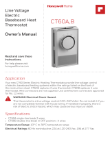
FIG. 2-MOUNTING AND LOCATION CONSIDERATIONS
• Locate the control between the boiler or furnace and draft regulator.
• Locate the control as near as possible to the boiler or furnace.
• If mounting in an elbow, locate the element near the outer curve where the
hottest gases flow.
• Do not locate the element where the temperature may exceed 1000° C [556°
C].
2.
Cut a 1-3/8 inch [35 millimeter] hole in the stack at the location desired.
3.
Drill two holes and fasten the mounting flange using the screws provided. The
flange should fit the mounting surface snugly, but it may be bent to fit a
different radius
stack or flattened to fit a flat surface. Do not force the collar or mounting
flange past the stop.
4.
Insert the bimetal element at the center of the stack in direct path of the
Honeywell RA116A, RA117A, RA817A Protectorelay Oil Burner Contro...
https://manuals.plus/honeywell/ra116a-ra117a-ra817a-protectorelay-oil-...
10 of 23
12/13/21, 5:50 PM

hottest flue gasses.
5.
Tighten the lockscrew.
WIRING
Follow the appliance manufacturer’s instructions, if available. Otherwise, follow
the wiring diagrams shown in Fig. 3 through 7.
WIRING DIAGRAMS
FIG. 3-RA116A WIRING DIAGRAM WITH A 24V, 3- WIRE
THERMOSTAT.
Honeywell RA116A, RA117A, RA817A Protectorelay Oil Burner Contro...
https://manuals.plus/honeywell/ra116a-ra117a-ra817a-protectorelay-oil-...
11 of 23
12/13/21, 5:50 PM

Honeywell RA116A, RA117A, RA817A Protectorelay Oil Burner Contro...
https://manuals.plus/honeywell/ra116a-ra117a-ra817a-protectorelay-oil-...
12 of 23
12/13/21, 5:50 PM

.
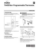
FIG. 7-RA817A WIRING DIAGRAM.
OPERATION
•
The schematic diagrams show all systems in the idle condition:
•
Burner off, no call for heat.
•
Pyrostat contacts closed {RA 116A).
•
“Cold” contacts closed, “hot” contacts open (RA 117 A, RA817A).
•
Safety switches closed.
•
All relays de-energized
NORMAL OPERATING SEQUENCE
On a thermostat (or line voltage controller) call for heat, the ignition, oil valve,
and burner motor start. The safety switch begins heating. After the burner flame
is established,
the stack temperature rises and expands the bimetal detector element. The
Pyrostat contacts open (RA 116A) or the “hot” contacts close and the “cold”
contacts open
{RA 117 A, RA817 A), de- energizing the safety switch heater.
The ignition circuit de-energizes (RA117A, RA817A only). When the call for heat
is satisfied, the system returns to the idle condition.
Honeywell RA116A, RA117A, RA817A Protectorelay Oil Burner Contro...
https://manuals.plus/honeywell/ra116a-ra117a-ra817a-protectorelay-oil-...
13 of 23
12/13/21, 5:50 PM

IGNITION FAILURE
If the burner flame is not established within approximately 75 seconds {nominal)
of a thermostat (or line voltage controller) call for heat, the Pyrostat contacts (RA
116A) or
“cold” contacts {RA 117 A, RAB 17 A) remain closed. During that time, the safety
switch is heated. If the burner flame is not established after 75 seconds
(nominal), the system locks out and cannot be started again until the safety
switch is manually reset.
CYCLE RA116A
The loss of burner flame reduces the stack temperature, closes the Pyrostat
contacts, and energizes the safety switch. If the burner flame is not re-established
within the
75 second (nominal) safety switch timing, the system locks out and cannot be
started again until the safety switch is manually reset. RA 117 A, RAB 17 A
The loss of burner flame reduces the stack temperature, opens the “hot” contacts,
and shuts the system down by de-energizing the 2K burner motor relay. After a
one
minute (approximate) scavenging period, the “cold” contacts close and energize
the safety switch heater. If the thermostat (or line voltage controller) is still
calling for heat,
the Protectorelay control makes one attempt to restart the system. If the burner
flame is not re-established in 75 seconds (nominal), the system locks out and
cannot be
started again until the safety switch is manually reset. POWER FAILURE
DURING THE RUNNING CYCLE A power failure shuts off the ignition and
burner motor.
If the thermostat is still calling for heat when power is restored, the stack
temperature must cool and return the system to the idle position. Once the
system returns to the
idle condition, it begins the normal operating sequence.
STARTUP AND CHECKOUT
FIRE HAZARD
CAN CAUSE SEVERE BURNS
Honeywell RA116A, RA117A, RA817A Protectorelay Oil Burner Contro...
https://manuals.plus/honeywell/ra116a-ra117a-ra817a-protectorelay-oil-...
14 of 23
12/13/21, 5:50 PM

Ensure the combustion chamber Is free of oil or oil vapor before starting system.
STEP THE PVROSTAT DETECTOR CONTACTS
The detector contacts are actuated by a friction clutch that is mounted on a rod
connected directly to the heatactuated element. Occasionally, this clutch gets
“out of
step” after a long period of idleness. To place the clutch and the contacts “in
step,”
1.
Remove the cover.
2.
Pull the lever forward 1/4 inch (Fig. 8).
3.
Slowly release the lever.
4.
Replace the cover
START THE SYSTEM
1.
Ensure the Pyrostat detectors are in step.
Honeywell RA116A, RA117A, RA817A Protectorelay Oil Burner Contro...
https://manuals.plus/honeywell/ra116a-ra117a-ra817a-protectorelay-oil-...
15 of 23
12/13/21, 5:50 PM

2.
Push in and release the safety switch reset button.
3.
Open the hand valve in the oil supply line.
4.
Set the limit control and thermostat to call for heat.
5.
Close the line switch. The burner should start.
CHECK THE SAFETY FEATURES
Simulate Flame Failure:
1.
Follow the starting procedure to turn on the burner.
2.
Close the hand valve in the oil supply line.
3.
The RA 116A locks out after 75 second (nominal) safety switch timing. The
RA117A and RA817A lock out after one minute (approximate) scavenging
period and 75
second (nominal) safety switch timing.
4.
Reset the safety switch and open the hand valve in the oil supply line.
Simulate Ignition Failure:
1.
Follow the starting procedure to turn on the burner, except do not open the oil
supply hand valve.
2.
Safety switch locks out after 75 second (nominal) safety switch timing.
Ignition and burner motor stops and oil valve closes.
3.
!Reset the safety switch and open the hand valve in the oil supply line.
Simulate Power Failure:
1.
Follow the starting procedure to turn on the burner.
2.
With the burner running, trip the circuit breaker or remove the fuse to turn off
Honeywell RA116A, RA117A, RA817A Protectorelay Oil Burner Contro...
https://manuals.plus/honeywell/ra116a-ra117a-ra817a-protectorelay-oil-...
16 of 23
12/13/21, 5:50 PM

power to the system. The burner should stop.
3.
Restore power. The burner should restart.
Check the Scavenger Timing:
1.
Follow the starting procedure to turn on the burner.
2.
With the burner operating normally, open and immediately close the line
switch. The burner should stop immediately.
3.
After recycle timing (one minute approximately), the burner should restart
automatically. If the system does not operate as described, proceed to
Troubleshooting.
TROUBLESHOOTING AND MAINTENANCE
To completely troubleshoot an oil burner installation, check the burner, ignition
transformer, and oil primary
control for proper operation and condition.
TRIP SAFETY SWITCH BEFORE OPERA TING BURNER MAINTENANCE
CAUTION
Tripping the safety switch shuts down the burner but does not disconnect the
power supply. Turn off the power at the system switch or the circuit breaker
before servicing the control system, burner motor, oil valve, or ignition to avoid
electrical shock.
Honeywell RA116A, RA117A, RA817A Protectorelay Oil Burner Contro...
https://manuals.plus/honeywell/ra116a-ra117a-ra817a-protectorelay-oil-...
17 of 23
12/13/21, 5:50 PM

To tri~the safety switch, move the safety switch lever down until the red reset
button pops out. Refer to Fig. 9.
The burner will not operate until the safety switch is reset by pushing the red
reset button.
PRELIMINARY STEPS
Before checking the oil primary and cad cell, check out the following parts of the
burner and ignition systems. Repair or replace controls as indicated.
1.
Wiring connections, power supply, and burner motor fuse. Ensure power is on
to the controls, burner motor, and ignition transformer.
2.
Limit switch.
3.
Ignition transformer.
Honeywell RA116A, RA117A, RA817A Protectorelay Oil Burner Contro...
https://manuals.plus/honeywell/ra116a-ra117a-ra817a-protectorelay-oil-...
18 of 23
12/13/21, 5:50 PM

4.
Electrode gap and position.
5.
Contacts between ignition transformer and electrode.
6.
Oil pump pressure.
7.
Oil tubing to tank.
8.
Oil nozzle.
9.
Oil supply.
10.
!Oil filter.
If the system is still not operating properly, check the oil primary control as
instructed below.
CHECK THE OIL PRIMARY CONTROL
CAUTION
Since troubleshooting is done with the system powered, observe all necessary
precautions to prevent electrical shock or equipment damage.
Equipment Required:
1.
Screwdriver
2.
Oto 300 Vac Voltmeter
3.
Insulated Jumper Wires
4.
Hard Surface Card (such as a business card) for
cleaning contacts
Burner Does Not Start When Thermostat Calls For Heat
PRELIMINARY CHECKS
1.
Ensure all limit switches are closed.
2.
Ensure safety switch is reset.
Honeywell RA116A, RA117A, RA817A Protectorelay Oil Burner Contro...
https://manuals.plus/honeywell/ra116a-ra117a-ra817a-protectorelay-oil-...
19 of 23
12/13/21, 5:50 PM

3.
Check for the proper line voltage at the oil primary. Proceed as follows after
completing the preliminary checks.
Burner Starts, Flame Is Established. Then Safety Switch Locks Out on Safety.
PRELIMINARY STEPS:
1.
Reset the safety switch.
2.
Clean bimetal detector contacts. Proceed as follows after completing the
preliminary checks.
Honeywell RA116A, RA117A, RA817A Protectorelay Oil Burner Contro...
https://manuals.plus/honeywell/ra116a-ra117a-ra817a-protectorelay-oil-...
20 of 23
12/13/21, 5:50 PM
/