Page is loading ...

Page 1
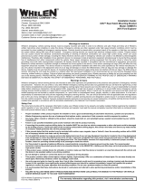
Model(s):
7110501 (14V Green)
7110502 (14V Red)
Model(s):
7110503 (28V Green)
7110504 (28V Red)
1.08
1.08
.67
1.25
1.25
RED (+14VDC)
BLACK (-)GROUND
20 AWG 6.00” ±1.00”
1.15
Model(s):
7110511 (28V Green)
7110512 (28V Red)
1.08
1.25
1.15
WHITE (+28VDC)
WHT/BLU (-)GROUND
SHIELD
2 CONDUCTOR
20 AWG ETFE CABLE
LEAD LENGTH
12.00” ±1.00”
WHITE (+28VDC)
BLACK (-)GROUND
20 AWG 6.00” ±1.00”
Model(s):
7110505 (28V Green)
7110506 (28V Red)
1.08
1.25
1.15
1/8" EXPANDABLE SLEEVING
TYPE: EXPANDO 686DM BLACK POS. A
POS. B
POS. C
WHT (28VDC)
N/C
BLK (GND)
The conditions and tests required for TSO approval of this
article are minimum performance standards. It is the
responsibility of those installing this article either on or
within a specific type or class of aircraft to determine that
the aircraft installation conditions are within the TSO
standards. TSO articles must have separate approval for
installation in aircraft. The article may be installed only if
performed under 14 CFR part 43 or the applicable
airworthiness requirements.
®
ENGINEERING COMPANY INC.
51 Winthrop Road
Chester, Connecticut 06412-0684
Phone: (860) 526-9504
Fax: (860) 526-2009
Internet: www.whelen.com
Sales/Service e-mail: aviation@whelen.com
Aviation
Installation Guide: 71105( )-series
Models 7110501, 02, 03, 04, 05, 06, 11, 12
P/N: 01-0771105-01, -02, -03, -04,
-05, -06, -11, -12
LED Forward Position
Light Assembly
©2007 Whelen Engineering Company Inc.
Form No.14099A (022808)
TSO-C30c
TYPES I & II
APPROVED
MADE IN THE U.S.A.
OPERATING INSTRUCTIONS:
Operational Voltage: . . . . . . . . .14/28 VDC (nominal)
Input Current:. . . . . . . . . . . . . . .0.25 Amps
EQUIPMENT LIMITATIONS: An approved forward
position lighting system consists of two lights, one located
on each wingtip.
CONTINUED AIRWORTHINESS: The 71105 series LED
wingtip position light assembly is designed with 3 LED’s. If
any one LED fails, the unit must be repaired or replaced.
Inspect the lens. Replace if there is excessive scratching,
discoloration or cracking.
INSTALLATION PROCEDURES: The following
information is to assist in the installation of a Whelen LED
Forward Position Light System.
1. Choose the appropriate 71105( ) series replacement
light assembly.
2. The installation procedure described in the
following text will be confined to a single light
installation, but is identical for multiple light
installations.
3. Remove the old light, locate and save the existing
+VDC lead and (-) ground lead. Clean and prep ends
as required.
4. Make sure the existing system is equipped with an
appropriate sized breaker. Connect the existing
+14/28 VDC lead to the POSITIVE wire on the input
cable assembly (supplied with the light assembly).
Connect the existing ground lead to the GROUND
wire on the input cable assembly or use the supplied
connector as shown in the illustrations. Both leads
must be connected by an approved FAA connection.
Insure that the wire leads clear of any obstructions
and ty-wrap as required.
5. Remove the shroud from the light assembly.
6. Position the base of the new light assembly onto the
mounting surface. Insert three (3) #6-32 pan head
screws into the mounting hole and tighten firmly.
Reinstall the lens so that the two notches are positioned under
the shroud, with each notch equadistant to the centerline.
7. Check all avionics systems for interference from the installation.
8. A flight check should be performed by a properly certified pilot.
9. Update aircraft records, complete Form 337 and obtain FAA
field approval for installation.

Page 2
ITEM PART NUMBER DESCRIPTION
7110501 LED FORWARD POS. LIGHT - 14V (GRN)
7110502 LED FORWARD POS. LIGHT - 14V (RED)
7101503 LED FORWARD POS. LIGHT - 28V (GRN)
7101511 LED FORWARD POS. LIGHT - 28V (GRN) w/SHIELD CABLE
7101504 LED FORWARD POS. LIGHT - 28V (RED)
7101512 LED FORWARD POS. LIGHT - 28V (RED) w/SHIELD CABLE
7101505 LED FORWARD POS. LIGHT - 28V (GRN) w/CONNECTOR
7101506 LED FORWARD POS. LIGHT - 28V (RED) w/CONNECTOR
01-0771105-01
01-0771105-02
01-0771105-03
01-0771105-11
01-0771105-04
01-0771105-12
01-0771105-05
01-0771105-06
QTYQTYQTY QTY QTY QTY QTY QTY
*
*
*
*
*
*
*
*
1
1
1
1
ASSY, POS. LIGHT 28V (GREEN) 71105-SERIES w/SHIELD CABLE
ASSY, POS. LIGHT 28V (GREEN) 71105-SERIES w/CONNECTOR
ASSY, POS. LIGHT 28V (RED) 71105-SERIES
ASSY, POS. LIGHT 14V (GREEN) 71105-SERIES
01-0771134-01
ASSY, POS. LIGHT 28V (GREEN) 71105-SERIES
01-0771134-03
01-0771134-11
01-0771104-05
ASSY, POS. LIGHT 14V (RED) 71105-SERIES
01-0771134-02
01-0771134-04
ASSY, POS. LIGHT 28V (RED) 71105-SERIES w/SHIELD CABLE
ASSY, POS. LIGHT 28V (RED) 71105-SERIES w/CONNECTOR
01-0771134-12
01-0771104-06
1
GASKET, W-1283/W-1285/A650
38-0230021-00
1SCREW, 6-32 x 5/16 (PFHMS / CSNK MS51959-27)
14-0050508-27
11111111
3
4
5
7
9
6
8
10
11
12
2
LENS, CLEAR FORWARD POSITION LIGHT HARDCOAT
68-3950902A30
RETAINER, FORWARD POSITION LENS CLEAR IRIDITE
19-150002-010
1
1
1
1
1
1
1
1
1
111
111
111
1
1
1
1
1
1
1
1
1
Mounting Dimensions
1.75
1.31
1.00
.50
.820
3 x .140
Mounting Hole
for #6-32 Screws
57
44
33
2 2
11
68
Models:
7110501, 7110502
Models:
7110503, 7110504
RED (+14 VDC)
BLACK (-) GROUND WHITE (+28 VDC)
BLACK (-) GROUND
9
4
3
2
1
10
Models:
7110511, 7110512
WHITE (+28 VDC)
WHITE/BLUE (-) GROUND
SHIELD
11
4
3
2
1
12
Models:
7110505, 7110506
POS. A
POS. B
POS. C
WHT (28VDC)
N/C
BLK (GND)
/