Page is loading ...

Instruction Manual
DE: Bedienungsanleitung - de.startech.com
FR: Guide de l'utilisateur - fr.startech.com
ES: Guía del usuario - es.startech.com
IT: Guida per l'uso - it.startech.com
NL: Gebruiksaanwijzing - nl.startech.com
PT: Guia do usuário - pt.startech.com
Manual Revision: 01/08/2013
For the most up-to-date information, please visit: www.startech.com
Packaging Contents
• Fiber Media Converter (2 x for ET90110WDM2)
• Universal Power Adapter (2 x for ET90110WDM2)
• Power Adapter PlugS (2 Sets of NA/ UK/ EU for ET90110WDM2)
• Instruction Manual
ET90110WDM2 / ET90110SM302
10/100 Mbps Ethernet to Single Mode SC WDM Fiber Media Converter Kit - 20km/30km
System Requirements
• 10BASE-T or 100Base-TX compatible Ethernet network equipment
• RJ45 terminated UTP Cat5 or better Ethernet cable
• 100BASE-FX compatible ber optic network equipment
• SC terminated single mode 9/125 micron (μm) ber optic cable
• Available AC electrical outlet
Installation
1. Make sure the DIP switches are set appropriately for your network
conguration (see “DIP Switch Settings“ section for details).
2. Setup the media converters at each of their respective end point locations.
3. Connect the ber optic network cable from one media converter
to the other media converter.
4. Connect a UTP Ethernet cable, from a computer/switch to the
RJ45 jack on the media converters at each end point.
5. Connect the included power adapters to the media converters.
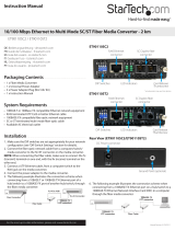
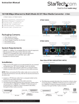
6. The following example illustrates the connection scheme
when connecting from a 100BASE-TX Ethernet port on a
hub/switch to a 100BASE-TX Ethernet Network Interface
Card (NIC) in a computer through the ber media converter:
DC Power connector
Ground Point (optional)
Rear View
ET90110WDM2 - Front View
RJ45 Ethernet
connector
SC ber
connector
DIP Switches LED indicators Card Release
Thumbscrew
RJ45 Ethernet
connector
SC Duplex ber
connector
DIP Switches LED indicators Card Release
Thumbscrew
ET90110SM302 - Front View

FCC Compliance Statement
This equipment has been tested and found to comply with the limits for a Class B digital device, pursuant to part 15 of the FCC Rules. These limits are designed to provide reasonable protection against
harmful interference in a residential installation. This equipment generates, uses and can radiate radio frequency energy and, if not installed and used in accordance with the instructions, may cause
harmful interference to radio communications. However, there is no guarantee that interference will not occur in a particular installation. If this equipment does cause harmful interference to radio or
television reception, which can be determined by turning the equipment o and on, the user is encouraged to try to correct the interference by one or more of the following measures:
• Reorient or relocate the receiving antenna.
• Increase the separation between the equipment and receiver.
• Connect the equipment into an outlet on a circuit dierent from that to which the receiver is connected.
• Consult the dealer or an experienced radio/TV technician for help.
Use of Trademarks, Registered Trademarks, and other Protected Names and Symbols
This manual may make reference to trademarks, registered trademarks, and other protected names and/or symbols of third-party companies not related in any way to
StarTech.com. Where they occur these references are for illustrative purposes only and do not represent an endorsement of a product or service by StarTech.com, or an endorsement of the product(s)
to which this manual applies by the third-party company in question. Regardless of any direct acknowledgement elsewhere in the body of this document, StarTech.com hereby acknowledges that all
trademarks, registered trademarks, service marks, and other protected names and/or symbols contained in this manual and related documents are the property of their respective holders.
Technical Support
StarTech.com’s lifetime technical support is an integral part of our commitment to provide industry-leading solutions. If you ever need help with your product, visit www.startech.com/support and access
our comprehensive selection of online tools, documentation, and downloads.
For the latest drivers/software, please visit www.startech.com/downloads
Warranty Information
This product is backed by a two year warranty.
In addition, StarTech.com warrants its products against defects in materials and workmanship for the periods noted, following the initial date of purchase. During this period, the products may be returned
for repair, or replacement with equivalent products at our discretion. The warranty covers parts and labor costs only. StarTech.com does not warrant its products from defects or damages arising from
misuse, abuse, alteration, or normal wear and tear.
Limitation of Liability
In no event shall the liability of StarTech.com Ltd. and StarTech.com USA LLP (or their ocers, directors, employees or agents) for any damages (whether direct or indirect, special, punitive, incidental,
consequential, or otherwise), loss of prots, loss of business, or any pecuniary loss, arising out of or related to the use of the product exceed the actual price paid for the product. Some states do not allow
the exclusion or limitation of incidental or consequential damages. If such laws apply, the limitations or exclusions contained in this statement may not apply to you.
Specications
Supported Standards IEEE 802.3, IEEE 802.3u
Connectors
1 x RJ45 Ethernet female
1 x SC Fiber female
1 x DC Power
Compatible Fiber Type Single Mode, 9/125 micron
Optical Wavelength 1310 nm
Maximum Distance 20 km (12.4 mi)
Duplex Modes Full/Half
Auto MDIX Yes (Ethernet)
Power Adapter 12V DC, 1000mA, center positive,
type M plug
Enclosure Material Metal
Operating Temperature 0°C ~ 60°C (32°F ~ 140°F)
Storage Temperature -10°C ~ 70°C (14°F ~ 158°F)
Humidity 10% ~ 90% RH
Dimensions (LxWxH) 160.0mm x 95.0mm x 20.0mm
Weight 600g
LED Status
LED Name Status Description
PWR Power ON Unit is powered
OFF Unit is not powered
FEF Far End Fault ON Link Fault on far end device
OFF No Link Faults
LNK
(FX) Fiber Link
ON Fiber link is detected
OFF Fiber link is not detected
Blink Data transmission
100 Ethernet Link
Speed
ON 100 Mbps
OFF 10 Mbps
Full Ethernet
Duplex Mode
ON Full Duplex Mode
OFF Half Duplex Mode
LNK
(TX) Ethernet Link
ON Ethernet Link detected
OFF Ethernet Link not detected
Blink Data Transmission
DIP Switch Settings
LFP:
Link Fault Pass-through will pass a link failure to the Ethernet side,
if a link failure is encountered on the ber side and vice versa.
Otherwise, the Ethernet side will continue to show no link failures,
even if the ber side has no link. (OFF = Not active, On = Active)
Full/ Half:
Ethernet Duplex mode will be congured for Full or Half.
10/ 100:
Set the Ethernet side link speed to 10 or 100 Mbps.
Auto/Manual:
Auto negotiate Link Speed and Duplex mode or manually set via
DIP switches.
/