Page is loading ...


Safety Instructions ...................................................................... 3
Specifications .............................................................................. 3
Installation ................................................................................... 4
Wiring .......................................................................................... 5
Common Uses ....................................................................................... 7
Dehumidier Lock-Off or Lock-On ......................................................... 8
Testing ................................................................................................... 9
Troubleshooting ................................................................................... 10
Operation ................................................................................... 11
Display .................................................................................................. 11
Set Up ..................................................................................................11
Setting Clock Time .............................................................................. 12
Adjusting the Relative Humidity Setpoint ............................................ 12
Temperature Cutout Programming ...................................................... 12
Fan Setting and Operation .................................................................. 13
Damper Operation and Ventilation, Manual (Hold) Mode .................... 13
Damper Operation and Ventilation, Programmed Ventilation .............. 14
Setting the Ventilation Program ........................................................... 14
Remote Sensor Option ............................................................... 16
Warranty .................................................................................... 17
TABLE OF CONTENTS
Ultra-Aire is committed to manufacturing quality products. To maintain
our standards, product specications may change without notice.
4201 Lien Road, Madison, WI 53704
(800) 533-7533
www.Thermastor.com | www.Ultra-Aire.com
© 2018 Therma-Stor LLC

3
www.Ultra-Aire.com | (800) 533-7533 Ultra-Aire DEH 3000/R Installation Instructions
SAFETY INSTRUCTIONS
WARNING!
THIS SYMBOL MEANS IMPORTANT INSTRUCTIONS. FAILURE TO HEED THEM
CAN RESULT IN SERIOUS INJURY OR DEATH.
READ THE INSTALLATION, OPERATION AND MAINTENANCE INSTRUCTIONS CAREFULLY
BEFORE INSTALLING AND OPERATING THIS DEVICE. PROPER ADHERENCE TO THESE
INSTRUCTIONS IS ESSENTIAL TO OBTAIN MAXIMUM BENEFIT FROM YOUR ULTRA-AIRE
WHOLE HOUSE VENTILATING DEHUMIDIFIER.
CAUTION!
THIS SYMBOL MEANS IMPORTANT INSTRUCTIONS. FAILURE TO HEED THEM
CAN RESULT IN INJURY OR MATERIAL PROPERTY DAMAGE.
SPECIFICATIONS
DEH 3000 Part Number: 4028539
DEH 3000R Part Number: 4028407
Operating Voltage: 24 VAC
Max Current - DMP, COMP, FAN: 1 Amp each
Humidity Range/Accuracy: 10 - 95% RH,
±
5%
Auxillary Relay Capacity: 5 Amps, 24 VAC
Temp Range/Accuracy: 30°-90° F, 2%
Dimensions:
Width: 1.06"
Height: 4.19"
Length: 4.95"

4Ultra-Aire DEH 3000/R Installation Instructions www.Ultra-Aire.com | (800) 533-7533
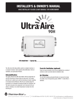
Install the DEH 3000 control or the remote sensor portion of the DEH 3000R in a central area of the structure where
it will sense the relative humidity of the structure accurately. Do not install the control panel or remote sensor where
it may not accurately sense the relative humidity such as near HVAC supply registers, near exterior doors and
windows, or near a pool or spa. Install in accordance with all applicable codes and standards.
1. Separate the front panel from the back panel by depressing the middle sections of the top and bottom of the
front panel.
2. Locatethewiringaccessholeinthewallorotheratmountingsurface.Placethebackpanelintopositionand
drill the appropriate mounting holes.
3. Insert the screws and tighten. Level as necessary.
4. Make the electrical connections to the terminals on the back panel as shown in the applicable wiring diagram
(Page5).
5. Testtheinstallation(Page9).
INSTALLATION
Mounting Hole
Mounting Hole
24 V COM
DMPR DEHU FAN
ON-Detect
Common
OFF-Detect
Normally
Open
Common
Normally
Closed
Optional
Use Optional
Use

5
www.Ultra-Aire.com | (800) 533-7533 Ultra-Aire DEH 3000/R Installation Instructions
WIRING
WARNING!
DO NOT ALLOW THE YELLOW WIRE OR +24V TERMINAL ON THE ULTRA-AIRE DEHUMIDIFIER
TO COME IN ELECTRICAL CONTACT WITH THE RED/WHITE WIRES OR COM/DMPR TERMINALS
ON THE ULTRA-AIRE DEHUMIDIFIER OR DAMAGE TO THE TRANSFORMER WILL RESULT.
WARNING!
THE REMOTE CONTROL OF THE ULTRA-AIRE DEHUMIDIFIER OPERATES ON A LOW VOLTAGE
CIRCUIT (24 VAC) AND MUST NEVER CONTACT OR BE CONNECTED TO A HIGH VOLTAGE CIRCUIT.
WARNING!
UNPLUG THE ULTRA-AIRE DEHUMIDIFIER BEFORE WIRING THE DEH 3000/R.
Theinstallermustsupplyalleldwiring,includingthewiringbetweentheUltra-Airedehumidierandthe
DEH3000/R.Someofthecontrolwiresorterminalsonthedehumidiermaynotbeusedinsomecontrol
situationsandshouldbeleftdisconnectedwithwirenutstapedontothestrippedends(ifnecessary).
Be sure to consult the electrical schematic in this manual or the internal electrical box of the Ultra-Aire
dehumidierbeforemakinganycontrolconnectionsasitmayvarybymodel.
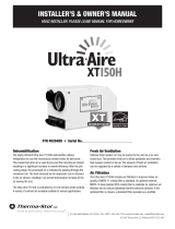
Terminal Block Conguration Version 2Terminal Block Conguration Version 1

6Ultra-Aire DEH 3000/R Installation Instructions www.Ultra-Aire.com | (800) 533-7533
TheWhitewirecontrolstheoptionalmotorizeddamperthatcanbeinstalledintoafreshairduct.This
damper provides the ability to control fresh air ventilation using the ventilation timer function of the DEH
3000/Randtheterminallabeled“DMP”ontheDEH3000/R(Page13).Leavethe“DMP”terminalunusedif
amotorizeddamperisnotused.
WIRING
WARNING!
ONLY CONNECT THE DMPR TERMINAL TO THE CONTROL IF IT IS WIRED IN A CIRCUIT
THROUGH AN ELECTRIC DAMPER, OTHERWISE TRANSFORMER DAMAGE MAY RESULT.
Standard Wire Colors for Thermostats:
24VAC Red R
Call for Heat White W or W1
Force Fan On Green G
Compressor
Call for Cooling Yellow Y or Y1
Terminal Block Control Operation:
Terminal Function Version 1:
COM 24Vac Power Transformer Neutral Side
FAN Fan Control
24V Transformer High Side
DEHU Dehumidication
(Fan and Compressor) Control
DMPR 24Vac Power Transformer Neutral Side
* Spare Terminal (Open)
Terminal Function Version 2:
COM 24Vac Power Transformer Neutral Side
FAN Fan Control
24V Transformer High Side
DEHU Dehumidication
(Fan and Compressor) Control
FLOAT External low voltage oat switch or water
sensor (use normally closed switch)
FLOAT External low voltage oat switch or water
sensor (use normally closed switch)
NO
COM
NC
Auxiliary Relay Operation
It may be desirable to coordinate fan
operation of the central heating/cooling
systemwithdehumidierfanoperation.
TheDEH3000/Rcontainsarelaythat
provides this ability.
TherelayterminalslabeledNC,COMand
NO operate according to the following chart:
FAN COM to NO COM to NC
ON CONNECTED OPEN
OFF OPEN CONNECTED

7
www.Ultra-Aire.com | (800) 533-7533 Ultra-Aire DEH 3000/R Installation Instructions
WIRING
Common Uses
(assumingstandardthermostatwiringcolorsasnoted):
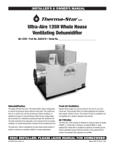
Lock-Out the A/C During Dehumidier Fan Operation (Figure 1)
ThiswillturnotheA/Cwheneverthedehumidierfanruns.
1.WiretheYellowthermostatterminaltotheNCterminalontheDEH3000/R.
2.RuntheYellowwirefromtheA/CunittotheCOMterminalontheDEH3000/R.
Energize the A/C Central Fan During Dehumidier Fan Operation (Figure 2)
ToautomaticallyruntheA/CFANwhenthedehumidierfanruns.
1. Attach a second Green wire to the FAN terminal on the thermostat.
2. Connect the new Green wire to the COM terminal on the DEH 3000/R.
3.RunawirefromtheRedterminalonthethermostattotheNO(NormallyOpen)terminalontheDEH3000/R.
Figure 1
DEH 3000
HVAC THERMOSTAT
NC
COM
RED
GREEN
YELLOW
COMP
FAN
24VAC
YELLOW
A/C
UNIT
A/C
TRANSFORMER
COM
BLAC
K
Figure 2
DEH 3000
HVAC THERMOSTAT
NO
COM
RED
GREEN
GREEN
COMP
FAN
24VAC
A/C
UNIT
A/C
TRANSFORMER
COM
BLAC
K
YELLOW
RED

8Ultra-Aire DEH 3000/R Installation Instructions www.Ultra-Aire.com | (800) 533-7533
WIRING
Dehumidifier Lock-Off or Lock-On
A/C Sensor Feature
Toautomaticallyactivateordeactivatethedehumidierwhentheair
conditioner runs.
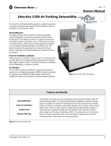
Activate Dehumidication When the A/C is Running
(Figure 3)
A voltmeter is required for the next steps to ensure the correct wiring
fromtheA/CtransformerisusedtosetuptheLock-Ondehumidier
function.
1.ThecommonwirefromtheexistingA/Ctransformer(usuallyBlack)
mustbeattachedtothe“COM”sensorterminalbetween“ON-D”
and“OFF-D”ontheDEH3000/R.
TIP: The common wire can be identied as the wire from the A/C transformer that reads 0 volts between it and the
Yellow air conditioning call for cooling wire. The incorrect wire will give a 20 to 28 volt reading.
2.AnotherYellowwiremustbeaddedtothethermostatYellowterminalandruntothe“ON-D”sensorterminalon
the DEH 3000/R.
ON-D
COM
OFF-D
Deactivate Dehumidication When the A/C is Running (Figure 4)
A voltmeter is required for the next steps to ensure the correct wiring from the A/C transformer is used to set
uptheLock-Odehumidierfunction.
1. ThecommonwirefromtheexistingA/Ctransformer(usuallyBlack)mustbeattachedtothe“COM”sensor
terminalbetween“ON-D”and“OFF-D”ontheDEH3000/R.
TIP: The common wire can be identied as the wire from the A/C transformer that reads 0 volts between it and
the Yellow air conditioning call for cooling wire. The incorrect wire will give a 20 to 28 volt reading.
2.AnotherYellowwiremustbeaddedtothethermostatYellowterminalandruntothe“OFF-D”sensor
terminal on the DEH 3000/R.
Figure 3
DEH 3000
HVAC THERMOSTAT
ON-DETECT
COM
RED
GREEN
COMP
FAN
24VAC
A/C
UNIT
A/C
TRANSFORMER
COM
BLAC
K
YELLOW
YELLOW
BLAC
K
Figure 4
DEH 3000
HVAC THERMOSTAT
OFF-DETECT
COM
RED
GREEN
COMP
FAN
24VAC
A/C
UNIT
A/C
TRANSFORMER
COM
BLAC
K
YELLOW
YELLOW
BLAC
K

9
www.Ultra-Aire.com | (800) 533-7533 Ultra-Aire DEH 3000/R Installation Instructions
WIRING
Testing
Verify the wiring connections.
WARNING!
ONLY CONNECT THE DMPR TERMINAL TO THE CONTROL IF IT IS WIRED IN A CIRCUIT THROUGH
AN ELECTRIC DAMPER, OTHERWISE TRANSFORMER DAMAGE MAY RESULT.
After checking the wiring, this short test will conrm proper hook-up.
1. Install front cover of the DEH 3000/R; connect the top rst, then the bottom.
2. Plug in the Ultra-Aire dehumidier. The DEH 3000/R should power up.
3. Turn the DEH 3000/R ON by pressing the “ON/OFF” button.
4. Verify dehumidication operation by adjusting the RH “SETPOINT” to below the “%RH” reading on the
display. Use the down “RH” button. Conrm Ultra-Aire fan and compressor operation. Both should be ON
now.
Increase the RH “SETPOINT” on the display to well above the “%RH” reading on the display. Press the “RH”
up arrow to increase the RH “SETPOINT”.
After running the dehumidier compressor, the DEH 3000/R applies a 10 minute restart lockout on all
functions. You will have to wait for the restart lockout to expire.
5. Verify FAN-only operation:
a. Check the “VENT” mode on the display, it will either be “CLOSED” or “OPEN”. If it is “CLOSED”, go
to the next step. If it is “OPEN”, press and hold the “VENT” key until “OPEN” ashes on the display,
release the key and then press it one more time. “OPEN” will change to “CLOSED”. Don’t touch the
keys for several seconds until it stops ashing.
b. Press and hold the “FAN” button until “AUTO” begins ashing on the display, release it, and then press
it again to switch the fan to the “ON” setting.
c. Conrm that the Ultra-Aire fan is ON. Ultra-Aire compressor must be OFF. Ventilation damper (if used)
should be CLOSED.
6. Verify optional VENT operation (if electric damper is installed):
a. Press and hold the “FAN” button until “ON” ashes on the display.
b. Release the “FAN” button, then press it again to switch fan operation to “AUTO”.
c. Press and hold the “VENT” button until “CLOSED” ashes on the display.
d. Release the “VENT” button, then press it again to switch vent mode to “OPEN”.
e. Conrm that the Ultra-Aire fan is ON. Ventilation damper is OPEN. Ultra-Aire compressor must be OFF.
f. Press and hold the “VENT” button until the “OPEN” ashes on the display.
g. Release the “VENT” button, then press it again to switch vent mode to “CLOSED”.
WARNING!
DO NOT MAKE ANY OTHER CONNECTIONS OR TRANSFORMER DAMAGE MAY RESULT.
7. Verify any additional optional control operations such as fan interlock or A/C lock-out.
8. Proceed to the Operation section (Page 11).

10 Ultra-Aire DEH 3000/R Installation Instructions www.Ultra-Aire.com | (800) 533-7533
WIRING
Symptom Possible Reason Troubleshooting Procedure
CAUTION!
TROUBLESHOOTING SHOULD BE PERFORMED BY A QUALIFIED HVAC TECHNICIAN.
1. Verify unit has power.
2. Turn unit off then on.
3. Disconnect the unit from power source then
re-apply power to the unit. Display should
now operate.
No display on initial
start up.
This is often the result of
a drained capacitor. The
capacitor will recharge once
power is applied or re-
applied to the unit.
Troubleshooting
WARNING!
ELECTRICAL SHOCK HAZARD. ELECTRICAL POWER MUST BE PRESENT TO PERFORM
SOME TESTS. THESE TESTS SHOULD BE PERFORMED BY A QUALIFIED SERVICE PERSON.
Function not
working properly.
1. Verify wiring.
2. Verify voltage with voltmeter.
Dehumidier not
working properly.
See chart below:
Wire Terminal
Connections Connections Operation
Yellow & Blue 24V and DEHU Fan & Compressor
Yellow & Green 24V and FAN Fan Only
Note: A jumper or normal closed oat switch must
be installed from FLOAT to FLOAT.

11
www.Ultra-Aire.com | (800) 533-7533 Ultra-Aire DEH 3000/R Installation Instructions
OPERATION
Onthedisplayscreen,asolid“O”infrontofanyofthe3functions(SETPOINT,VENT,FAN)indicatesthe
functionisoperating.Aashing“O”indicatesitisinawaitmodeandnotavailableatthemoment.No“O”
indicates the function is currently OFF.
Solid “O” Before Indicates
SETPOINT Dehumidieron
VENT Freshairventilationcycleinprogress
FAN Fan on
Waitmodeisafactory-programmedtimeperiodmeanttopreventshortcycles.Thisextendsthelifeofthe
dehumidier.Whenaashing“O”isencountered,theunitisinwaitmodeandITCOULDBEUPTO10
MINUTESBEFOREOPERATIONRESUMES.
Display
•Wheneverthereispowertothecontrol,itwilldisplaythetime,the
day, % relative humidity, and temperature.
•WhenthecontrolisactuallyswitchedON,the%RHsetpoint,fan
status,runmode(programorhold),andfreshairventilationstatus
is displayed.
•Whenakeyispressedthedisplaywilllightforapproximately30
seconds.
•TimeandDayaredisplayedatthetopofthescreen.
•RHandTemperaturearedisplayedinrealtime.
•Asolid“O”beforetheSETPOINT,VENT,ORFANindicatesthe
function is operating.
•Aashing“O”beforetheSETPOINT,VENT,ORFANindicatesthe
unit is in wait mode.
•WhenthesystemisOFF,thecontrolwilldisplaythetime,day,
%RH, and temperature.
•Whentheunitisshipped,itisinmanual(hold)mode.
Set Up
During the set-up process, if you make a mistake, simply continue.
Youcanalwaysgobacktoadjustthesettings.Ifyouleavethe
control alone and don’t touch any buttons for 10 seconds, the
control will remember any changes made and return to the normal
display screen, allowing you to proceed to the next step.
For Installer and Homeowner:
DEH 3000/R ON
DEH 3000/R OFF

12 Ultra-Aire DEH 3000/R Installation Instructions www.Ultra-Aire.com | (800) 533-7533
OPERATION
Setting Clock Time
1.Pressandholdthe“CLOCK”button.Thehourdisplaywillash.Releasethebutton.
2.Usetheup/down“RH”buttonstochangethevalue.
3.Pressthe“CLOCK”buttonagainandtheminutedisplaywillash.Usethe“RH”buttonstochangethevalue.
4.Pressthe“CLOCK”buttonagainandAMorPMwillash.Usethe“RH”buttonstochangethevalue.
5.Pressthe“CLOCK”buttonagainandthedaydisplaywillash.Usethe“RH”buttonstochangethevalue.
6.Don’ttouchanybuttonsforseveralsecondsuntilthedisplaystopsashing,thiswillsaveyoursettings.Ifyouneed
to change anything, go back to step #1.
Adjusting the Relative Humidity “SETPOINT”
TheDEH3000/Rsensestheambientrelativehumidity(%RH)ofthe
spaceinwhichitislocated.Itcomesfactorypresettohold50%
relative humidity.
Therelativehumidity“SETPOINT”(desiredRHtobemaintained)operates
thedehumidierfunctionoftheUltra-Airedehumidier.Ithasnoeecton
theoptionalVENT(freshairventilation)orFAN(householdairrecirculation)
functions if they are being used.
Thestandardrangethatthedehumidierholdsaroundyour“SETPOINT”
is3%.Withasetpointof50%,thedehumidierwillrununtiltherelative
humidityreaches47%.Thedehumidierwillthenswitchountiltherelative
humidityreaches53%.
Ifthesetpointishigherthantheambientrelativehumidity,thespacedoesnotneedtobedehumidied,
sothedehumidierwillnotrun.
Example:Setpoint:50%RH
Currentcondition:45%RH–Thedehumidierwillbeo(no“O”indicatorwillbedisplayed).
Ifyoursetpointisbelowtheambientcondition,thedehumidierwillbeonand“O”willdisplay.
Example:Setpoint:50%RH
Currentcondition:55%RH–Thedehumidierwillbeon(“O”displayed).
Temperature Cutout Programming
Dehumidiersproduceheatwhendehumidifyinganddependinguponoutsideconditions,theventilation
function may also introduce warm air. Some conditions may introduce enough heat to drive household
temperaturesup.TheDEH3000/RtemperaturecutoutfeaturedisablesallUltra-Aireoperationsifhousehold
temperatures reach the cutout setpoint.
Inmostinstallationsthisfeaturewillnotneedtobeused(thecutoutisfactorysetto99°F).Ifalower
temperaturecutoutisdesired,programthesetpointbypressingandholdingthe“PROGRAMENTER”
buttonuntilthe“PROGRAM”screenappears.Presstheup/down“RH”buttonsuntil“TEMPCUTOUT”
highlighted.Thenpressthe“PROGRAMENTER”buttonagaintoselectit.Nowusethe“RH”upor“RH”
downbuttonstoadjustthesetpoint.Press“PROGRAMENTER”toreturntothehomescreen.
Personal Settings Reference List
Pleaserecordyoursettingshere.
Function Factory Setting My Setting
SETPOINT(%RH) 50%
VENT Closed
FAN Auto
TEMPCUTOUT 99°

13
www.Ultra-Aire.com | (800) 533-7533 Ultra-Aire DEH 3000/R Installation Instructions
OPERATION
Fan Setting and Operation
Usethe“FAN”buttontochangethefanoperation.Thereare2choicesforfanoperation:“ON”or“AUTO”.
Thefactorypresetis“AUTO”.
“ON”–ThefanintheUltra-Airedehumidierwillruncontinuously.Thisdoesnotaecteitherthe
dehumidicationorventilationfunctionsofthesystem.Thesystemmayormaynotbeventilatingor
dehumidifyingwhilethefanisrunning.Thissettingiscommonlyusedformaximumairltrationand/orair
recirculation.
“AUTO”–IndicatesthefanwillrunwhentheDEH3000/Rcallsfordehumidicationorventilation.
Ifthecontrolhasnotcalledfordehumidicationfor3hours,thecontrolwillautomaticallyrunthe
dehumidierfanfor10minutes.
Afteradehumidicationcycle,thefanautomaticallyshutsofor10minutes.Thispauseallowsthewaterto
drainfromthedehumidier.
Asolid“O”indicatesthefanisoperating.Aashing“O”indicatesthefanisinawaitmode.No“O”
indicates the fan is OFF.
To set the operation:
1.Pressandholdthe“FAN”button.Thecurrentfansettingwillbegin
toashonthedisplay.Releasethebutton.
2.Pressthe“FAN”buttontotogglebetweenthe“ON”and“AUTO”
modes.
Withthefaninthe“AUTO”mode,thefanwilloperateonlywhen
neededbyotherfunctionsofthesystem.ThefanwillremainOFF
unlessthesystemisdehumidifyingorventilating.Thefanalways
runsduringdehumidicationandventilationandthefan“O”icon
willbelit.TocompletelyturnthesystemOFF,usethe“ON/OFF”
button as described earlier.
Damper Operation and Ventilation, Manual (Hold) Mode
The“VENT”settingcontrolstheventilationfunctionofthesystem.Ithas
nocontroloverthedehumidicationfunction.Inordertoprovide
ventilation,themotorizeddampermustbeopenandthefanmustbe
running.Thecontrollertakescareofthesetwofunctionsautomatically
so that whenever the damper is open, the fan is running.
Theventilationindicator“O”willbedisplayedwhenevertheunitis
ventilating.Thefanoperationindicator“O”willalsobelit.
There are three damper operation modes:
1.“OPEN”–holdmode:Thedamperwillbeopenandthedehumidier
fan will be continuously operating to introduce fresh air into the space.
Usethismodeforcontinuousfreshairventilation.Thefanisalways
on when the damper is open.
2.“CLOSED”–holdmode:Thedamperwillneveropen,andthe
dehumidierwillnotventilate.Thefanwillstilloperatenormallyfor
recirculationanddehumidication.
3.“PROGRAM”mode:TheDEH3000/Rwilloperatethemotorized
damperandthedehumidierfanaccordingtotheprogrammed
ventilationschedule(Page14).
Thefactorypresetforthe“VENT”settingis“CLOSED”.
To set “OPEN” – hold or “CLOSED” – hold ventilation operation:
1.Pressthe“VENT”button.Thecurrentsettingwillbegintoashonthedisplay.Releasethebutton.
2.Pressthe“VENT”buttonagaintoswitchbetween“OPEN”and“CLOSED”.
3. Leave the control alone for 10 seconds and your settings will be saved.

14 Ultra-Aire DEH 3000/R Installation Instructions www.Ultra-Aire.com | (800) 533-7533
OPERATION
Damper Operation and Ventilation, Programmed Ventilation
Thisexampleshowsthesysteminprogrammodedenotedbythe
schedule15minuteson,5minutesoandthewordRUNinthelower
right corner of the display.
TheDEH3000/Rwilloperatefreshairventilationaccordingtoyour
ventilationprogram.Thecontrolneedstobeprogrammedtoturnthe
ventilationfunctionONandOFFatthedesiredintervals.Thisisdone
by programming the ventilation timer.
There are two programs available for ventilation:
1. Monday through Sunday
2. Monday through Friday & Saturday/Sunday
Eachblockofdayshasamorningscheduleandanightschedule.Morningistherst12hoursoftheday
and night is the second 12 hours.
Each schedule has:
•“START”timewhentheventilationschedulebegins
•“OPENFOR”durationfortheamountoftimethedamperstaysopenin5minuteintervalsfrom0to60
•“CLOSEDFOR”durationwhichclosesthedamperforaspeciedtimein5minuteintervalsfrom0to60
Setting the Ventilation Program
1.Pressthe“PROGRAMENTER”buttonuntilthemenutothe
right appears.
2.Usingtheup/down“RH”buttons,highlight“PROGRAM”and
selectitbypressingthe“PROGRAMENTER”button.
You can select from:
“MON-FRI”“SAT-SUN”forseparateweekdayandweekend
schedules,or“MON-SUN”whichgivesyouequalweekdayand
weekend schedules.
3.UsingtheUp/Down“RH”buttons,highlightandthenselect
one of the two choices.

15
www.Ultra-Aire.com | (800) 533-7533 Ultra-Aire DEH 3000/R Installation Instructions
OPERATION
Setting the Ventilation Program (Continued)
Thedisplaytotherightshowsthemenuwhenaseparateweekday
andweekendscheduleisselected(“MON-FRI”“SAT-SUN”).
1.Enterthestartingtimeforweekdaysusingtheup/down“RH”
buttons to change the time.
2.Pressthe“PROGRAMENTER”buttontoswitchtothe“OPENFOR”
setting.Usingtheup/down“RH”buttons,changethedurationthat
the damper will ventilate fresh air.
3.Pressthe“PROGRAMENTER”buttontoswitchtothe“CLOSEDFOR”setting.Usingtheup/down“RH”
buttons, change the duration that the damper will remain closed between ventilation cycles.
Fortheexamplegiven,startingat8:00AMinthemorning,thecontrolwillventilatefreshairfor15minutes
thenstopfor15minutes.Thisscheduleof15minutesopen,15minutesclosedwillcontinueuntilthestart
time of the night schedule.
Morningscheduleisavailableanytimefrom12:00AMuntil11:59AM.
Nightscheduleisavailableanytimefrom12:00PMuntil11:59PM.
4.Press“PROGRAMENTER”againtogotothe“MON-FRI”nightschedule.Repeatthestepslistedabove
forthisandthe“SAT-SUN”dayandnightschedules.
Whenyouhavenishedprogrammingyourschedule(eitherthe7-dayversionortheweekday/weekendsplit
version),usethedown“RH”buttontohighlighttheEXIToptionandthenpress“PROGRAMENTER”
to select it.
Running the Ventilation Program
Pressandholdthe“PROGRAMENTER”buttonuntilthe“PROGRAM”screenappearsasshownbelow.
Usethedown“RH”buttontohighlight“RUNPROGRAM”.
Thenpress“PROGRAMENTER”toselectit.Thedisplaybelowwillappear.

16 Ultra-Aire DEH 3000/R Installation Instructions www.Ultra-Aire.com | (800) 533-7533
REMOTE SENSOR OPTION
The remote sensing option is used when an installation requires mounting the DEH 3000 out of the
conditioned space or when it is desired to specically monitor and control the conditions at a particular
location in a larger conditioned space.
Both the need for and location of the remote sensor should be determined by a heating/cooling
professional. In most installations, the onboard sensor in the DEH 3000 will be sufcient to monitor and
control the conditioned space.
Install and Wiring Instructions
Routing Signal Wires
You will be required to supply and route 24 gauge, 4 conductor solid wire (2-line telephone wire) between
the DEH 3000R controller and the remote sensor location. The wiring run should be no longer than 100 ft.
Avoid routing this interconnect wire parallel to high voltage wiring. Maintain a distance of 2 ft. or more from
high voltage lines.
Sensor Connection
The sensor can be mounted to a wall or ceiling surface. Ideal sensor location is 5 ft. above the oor. Wires
should exit through a ½” diameter hole in the mounting surface at the mounting location. Use the provided
splice connectors to connect the 4 wires from the remote sensor to the user-supplied interconnect wire. Be
sure to keep proper colors attached to each other.
Sensor Mounting
You will need two screws to mount the sensor. Use the two slotted holes to mount the base of the sensor to
the wall and then snap the cover into place.
Controller Connection
Use the provided splice connectors to connect the 4 wires from the DEH 3000R to the user-supplied
interconnect wire. Be sure to keep the proper colors attached to each other.
Continue with the installation as described in the rest of this manual.
This section is applicable only to customers who have purchased a remote sensor package.
The standard DEH 3000 controller does not offer remote functionality.
WARNING!
THE USE OF SPRAY PAINT ON THE SENSOR HOUSING MAY DAMAGE THE SENSOR AND IS
NOT COVERED BY THE PRODUCT WARRANTY.

17
www.Ultra-Aire.com | (800) 533-7533 Ultra-Aire DEH 3000/R Installation Instructions
WARRANTY
Warrantor:
Therma-StorLLC
4201 Lien Road
Madison,WI53704
Telephone:(800)533-7533
Who Is Covered:Thiswarrantyextendsonlytotheoriginalresidentialend-useroftheDEH3000/RDehumidier&Ventilation
System Controller, and may not be assigned or transferred.
First Year Warranty:Therma-StorLLCwarrantsthat,forone(1)yeartheDEH3000/RDehumidier&VentilationSystem
Controllerwilloperatefreefromanydefectsinmaterialsandworkmanship,orTherma-StorLLCwill,atitsoption,repairor
replacethedefectivepart(s),freeofanycharge.
End-User Responsibilities:WarrantyservicemustbeperformedbyaServicerauthorizedbyTherma-StorLLC.Iftheend-
userisunabletolocateorobtainwarrantyservicefromanauthorizedServicer,heshouldcallTherma-StorLLCattheabove
numberandaskfortheTherma-StorLLCServiceDepartment,whichwillthenarrangeforcoveredwarrantyservice.Warranty
service will be performed during normal working hours.
TheEnd-usermustpresentproofofpurchase(lease)uponrequest,byuseofthewarrantycardorotherreasonableand
reliablemeans.Theend-userisresponsiblefornormalcare.Thiswarrantyonlyappliestoresidentialapplicationsanddoes
notcoveranydefect,malfunction,etc.resultingfrommisuse,abuse,lackofnormalcare,corrosion,freezing,tampering,
modication,unauthorizedorimproperrepairorinstallation,accident,actsofnatureoranyothercausebeyondTherma-Stor
LLC’s reasonable control.
Limitations and Exclusions:IfanyDEH3000/RDehumidier&VentilationSystemControllerpartisrepairedorreplaced,the
new part shall be warranted for only the remainder of the original warranty period applicable thereto (but all warranty periods
willbeextendedbytheperiodoftime,ifany,thattheDEH3000/RDehumidier&VentilationSystemControllerisoutof
servicewhileawaitingcoveredwarrantyservice).
UPONTHEEXPIRATIONOFTHEWRITTENWARRANTYAPPLICABLETOTHEDEH3000/RDehumidier&Ventilation
SystemControllerORANYPARTTHEREOF,ALLOTHERWARRANTIESIMPLIEDBYLAW,INCLUDINGMERCHANTABILITY
ANDFITNESSFORAPARTICULARPURPOSE,SHALLALSOEXPIRE.ALLWARRANTIESMADEBYTHERMA-STOR
LLCARESETFORTHHEREIN,ANDNOCLAIMMAYBEMADEAGAINSTTHERMA-STORLLCBASEDONANYORAL
WARRANTY.INNOEVENTSHALLTHERMA-STORLLC,INCONNECTIONWITHTHESALE,INSTALLATION,USE,REPAIR
ORREPLACEMENTOFANYDEH3000/RDehumidier&VentilationSystemControllerORPARTTHEREOFBELIABLE
UNDERANYLEGALTHEORYFORANYSPECIAL,INDIRECTORCONSEQUENTIALDAMAGESINCLUDINGWITHOUT
LIMITATIONWATERDAMAGE(THEEND-USERSHOULDTAKEPRECAUTIONSAGAINSTSAME),LOSTPROFITS,DELAY,
ORLOSSOFUSEORDAMAGETOANYREALORPERSONALPROPERTY.
Some states do not allow limitations on how long an implied warranty lasts, and some do not allow the exclusion or limitation
of incidental or consequential damages, so one or both of these limitation may not apply to you.
Legal Rights:Thiswarrantygivesyouspeciclegalrights,andyoumayalsohaveotherrightswhichvaryfromstatetostate.


/