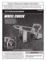
MOTORCYCLE WHEEL
CHOCK
Model
96349
SET UP AND OPERATING INSTRUCTIONS
Visit our website at: http://www.harborfreight.com
Read this material before using this product.
Failure to do so can result in serious injury.
SAVE THIS MANUAL.
Copyright© 2009 by Harbor Freight Tools®. All rights reserved. No portion of this manual or any
artwork contained herein may be reproduced in any shape or form without the express written
consent of Harbor Freight Tools. Diagrams within this manual may not be drawn proportionally.
Due to continuing improvements, actual product may differ slightly from the product described
herein. Tools required for assembly and service may not be included.
For technical questions or replacement parts, please call 1-800-444-3353.
Manual revised 09j

Page 2 For technical questions, please call 1-800-444-3353. SKU 96349
SPECIFICATIONS
Construction Formed Steel w/ Carbon
Steel Hardware &
Thermoplastic End Caps
Overall Dimensions 15-9/16” L X 10-3/8” W X
13-5/16” H
Weight 16 Pounds
Moveable Chock
Length 10”
Note: The Wheel Chock will t most
standard motorcycles currently on the
market. However, some models with
especially wide tires or custom low-
prole front fenders will not t into the
Wheel Chock.
Save This Manual
You will need this manual for
the safety warnings and precautions,
assembly, operating, inspection,
maintenance and cleaning procedures,
parts list and assembly diagram. Keep
your invoice with this manual. Write the
invoice number on the inside of the front
cover. Write the product’s serial number in
the back of the manual near the assembly
diagram, or write month and year of
purchase if product has no number. Keep
this manual and invoice in a safe and dry
place for future reference.
GENERAL SAFETY RULES
WARNING!
READ AND UNDERSTAND ALL
INSTRUCTIONS
Failure to follow all instructions
listed below may cause injury.
SAVE THESE INSTRUCTIONS
WORK AREA
Keep your work area clean and well 1. lit. Cluttered benches and dark areas
invite accidents.
Keep children and visitors away 2. while installing. Distractions can
cause you to lose control. Protect
others in the work area from debris
such as chips and sparks. Provide
barriers or shields as needed.
Store idle products out of reach 3. of children and other untrained
persons. Never allow children to play
with or around the Wheel Chock.
PERSONAL SAFETY
Stay alert. Watch what you are 1. doing, and use common sense
when using the Wheel Chock. Do
not use this product while tired
or under the inuence of drugs,
alcohol, or medication. A moment
of inattention while operating may
result in serious personal injury.
Dress properly. Do not wear loose 2. clothing or jewelry. Contain long
hair. Keep your hair, clothing, and
gloves away from moving parts.
Loose clothes, jewelry, or long hair
can be caught in moving parts.
Do not overreach. Keep proper 3. footing and balance at all times.
Proper footing and balance enables
better control of the motorcycle in
unexpected situations.
Use safety equipment. Always 4. wear eye protection. Dust
mask, nonskid safety shoes, hard
hat, heavy-duty work gloves, or
hearing protection must be used for
appropriate conditions. Always wear
ANSI-approved safety goggles and a
dust mask/respirator when installing
Rev 08a

Page 3For technical questions, please call 1-800-444-3353.SKU 96349
or performing maintenance on this
tool.
Maintain labels and nameplates 5. on the tool. These carry important
information. If unreadable or missing,
contact Harbor Freight Tools for a
replacement.
Maintain a safe working 6. environment. Make sure there is
adequate surrounding workspace. Do
not use this product in a damp or wet
location.
Use the correct product for 7. your motorcycle. Make sure the
motorcycle’s wheel ts into the Wheel
Chock prior to rst use.
UNPACKING
When unpacking, check to
make sure that the item is intact and
undamaged. If any parts are missing or
broken, please call Harbor Freight Tools
at the number shown on the cover of this
manual as soon as possible.
ASSEMBLY AND
INSTALLATION
INSTRUCTIONS
Note: For additional information regarding
the parts listed in the following pages,
refer to the Assembly Diagram at the
end of the manual.
The Wheel Chock comes fully assembled,
however it must be mounted onto a solid
surface to secure it. It is designed to
be mounted on the bed of a truck, or a
motorcycle lift, or onto a concrete oor.
Concrete Floor Mounting
Choose a location to install the Wheel 1.
Chock that is at, level, and capable
of bearing the combined weight of
the Wheel Chock and the motorcycle
being secured. Be certain that the
location will not obstruct walkways
and will still provide enough room
to retrieve the motorcycle after it
is mounted. The surface of the
location should be one suitable for the
mounting of heavy equipment.
Use the mounting holes in the Base 2. (7) of the Wheel Chock as a template.
Arrange the Base (7) in the chosen
location and, using a pencil, mark
where the holes are to be drilled.
You will need concrete anchors (not
included) to secure the Base (7) to
the concrete oor. Using the correct
size concrete drill bit (not included),
drill the mounting holes to secure
the Base (7). Attache the concrete
anchors to the oor. Secure the Base
(7) to the oor utilizing the concrete
anchors.
Truck Bed or Motorcycle Lift
Mounting
Place the Base (7) in the desired 1. location of the truck bed or motorcycle
lift that you want to mount it at. Use
the of the Base (7) as a pattern to
mark where you will drill the holes
that accept the hardware to mount the
Wheel Chock. Use a power drill (not
included) and a steel cutting drill bit
(not included) to drill holes in the truck
bed or motorcycle lift.
Warning: Verify that the installation
surface has no hidden wires, brake
lines, etc. before drilling.
Attach the Base (7) to the truck 2. bed utilizing the Mounting Bolts (6),
Nylon Sleeves (8), Large Washers
(9), Spring Washers (3), and secure
with Hex Nuts (10). See page 6,
assembly diagram.

Page 4 For technical questions, please call 1-800-444-3353. SKU 96349
OPERATING INSTRUCTIONS
Select the correct mounting hole for 1. the motorcycle being loaded into the
Wheel Chock, and use the Pivot Bolts
(5) to secure the Pivoting Bracket in
place.
Note: Do not sit on the motorcycle when it
is loaded in the Wheel Chock.
To load a motorcycle, lower the 2. Pivoting Bracket (13) to the horizontal
position and simply push the
motorcycle into the Wheel Chock.
The Pivoting Bracket will close on the 3. motorcycle tire, securing the bike in
an upright position.
For long-term storage, or if the 4. Wheel Chock is mounted to a mobile
platform, the motorcycle should be
secured with belts or straps (not
included).
INSPECTION,
MAINTENANCE, AND
CLEANING
BEFORE EACH USE, inspect the 1. general condition of the tool. Check
for loose screws, misalignment or
binding of moving parts, cracked or
broken parts, and any other condition
that may affect its safe operation. Do
not use damaged equipment.
Occasionally, wipe the Wheel Chock 2. down with a soft cloth and mild
detergent.
LIMITED 90 DAY WARRANTY
Harbor Freight Tools Co. makes every effort to
assure that its products meet high quality and
durability standards, and warrants to the original
purchaser that this product is free from defects in
materials and workmanship for the period of 90
days from the date of purchase. This warranty
does not apply to damage due directly or indirectly,
to misuse, abuse, negligence or accidents, repairs
or alterations outside our facilities, criminal
activity, improper installation, normal wear and
tear, or to lack of maintenance. We shall in no
event be liable for death, injuries to persons or
property, or for incidental, contingent, special or
consequential damages arising from the use of our
product. Some states do not allow the exclusion or
limitation of incidental or consequential damages,
so the above limitation of exclusion may not apply
to you. This warranty is expressly in lieu of all
other warranties, express or implied, including the
warranties of merchantability and tness.
To take advantage of this warranty, the product
or part must be returned to us with transportation
charges prepaid. Proof of purchase date and an
explanation of the complaint must accompany the
merchandise. If our inspection veries the defect,
we will either repair or replace the product at our
election or we may elect to refund the purchase
price if we cannot readily and quickly provide
you with a replacement. We will return repaired
products at our expense, but if we determine
there is no defect, or that the defect resulted from
causes not within the scope of our warranty, then
you must bear the cost of returning the product.
This warranty gives you specic legal rights and
you may also have other rights which vary from
state to state.
3491 Mission Oaks Blvd. • PO Box 6009 •
Camarillo, CA 93011 • (800) 444-3353

Page 5For technical questions, please call 1-800-444-3353.SKU 96349
PLEASE READ THE FOLLOWING CAREFULLY
THE MANUFACTURER AND/OR DISTRIBUTOR HAS PROVIDED THE PARTS LIST AND
ASSEMBLY DIAGRAM IN THIS MANUAL AS A REFERENCE TOOL ONLY. NEITHER THE MANU-
FACTURER OR DISTRIBUTOR MAKES ANY REPRESENTATION OR WARRANTY OF ANY KIND
TO THE BUYER THAT HE OR SHE IS QUALIFIED TO MAKE ANY REPAIRS TO THE PRODUCT, OR
THAT HE OR SHE IS QUALIFIED TO REPLACE ANY PARTS OF THE PRODUCT. IN FACT, THE
MANUFACTURER AND/OR DISTRIBUTOR EXPRESSLY STATES THAT ALL REPAIRS AND PARTS
REPLACEMENTS SHOULD BE UNDERTAKEN BY CERTIFIED AND LICENSED TECHNICIANS,
AND NOT BY THE BUYER. THE BUYER ASSUMES ALL RISK AND LIABILITY ARISING OUT OF
HIS OR HER REPAIRS TO THE ORIGINAL PRODUCT OR REPLACEMENT PARTS THERETO,
OR ARISING OUT OF HIS OR HER INSTALLATION OF REPLACEMENT PARTS THERETO.
PARTS LIST
Part Description Qty
1 Main Frame 1
2 Hex Bolt M10x20 4
3 Spring Washer 8
4 Flat Washer 4
5 Pivot Bolt M10x30 2
6 Bolt M10x70 4
7 Base 1
8 Nylon Sleeve 4
9 Large Washer 4
10 Hex Nut M10 6
11 Nylon Washer 2
12 Rubber Cap 4
13 Pivoting Bracket 1

/