1
INSTRUCTION MANUAL
ROTATING LASER
RL-H3C
RL-H3CL
RL-H3CS
RL-H3C_CL_CS.fm Page 1 Monday, June 12, 2006 9:47 AM

2
RL-H3C_CL_CS.fm Page 2 Monday, June 12, 2006 9:47 AM

3
Introduction
Thank you for purchasing the TOPCON Rotating Laser.
The instrument has many unique features. For basic operation, rough level the
instrument and press power switch. It will self-level, then emit a rotating laser
beam.
The RL-H3CS Rotating Laser creates a level reference plane. The laser pro-
vides controls that allow the beam plane to be tilted up to 5 degrees for single
slope applications.
For superior product performance, please read these instructions carefully and
keep them in a convenient place for future reference.
RL-H3C_CL_CS.fm Page 3 Monday, June 12, 2006 9:47 AM

4
STANDARD PACKAGE COMPONENTS
Upon opening, make sure that all the followings are included:
RL-H3C / RL-H3CL
1 RL-H3C / RL-H3CL Instrument. . . . . . . 1set
2 LS-70B/70C* Laser Sensor. . . . . . . . . . 1set
3 Size "C" dry batteries (R14PU). . . . . . . 4pc.
4 9 volt dry battery (6F22/S-006P). . . . . . 1pc.
5 Carrying case . . . . . . . . . . . . . . . . . . . . 1pc.
6 Instruction manual. . . . . . . . . . . . . . . . . 1vol.
7 Model-6 Laser Sensor Holder. . . . . . . . 1pc.
* LS-70B is included for some markets instead of LS-70C
RL-H3CS
1 RL-H3CS Instrument. . . . . . . . . . . . . . . 1set
2 LS-70B Laser Sensor . . . . . . . . . . . . . . 1set
3 Size "C" dry batteries (R14PU). . . . . . . 4pc.
4 9 volt dry battery (6F22/S-006P). . . . . . 1pc.
5 Carrying case . . . . . . . . . . . . . . . . . . . . 1pc.
6 Instruction manual. . . . . . . . . . . . . . . . . 1vol.
7 Model-6 Laser Sensor Holder. . . . . . . . 1pc.
GENERAL HANDLING PRECAUTIONS
Before starting work or operation, be sure to check that the instrument is func-
tioning correctly with normal performance.
When storing the instrument for long period, remove the batteries. Always
make sure instrument is dry before putting it in the carrying case. Never store
a damp instrument.
STORAGE PRECAUTIONS
Always clean the instrument after use.
Use a clean cloth moistened with neutral detergent or water.
Never use an abrasive cleaner, ether, thinner benzene, or other solvents.
Always make sure the instrument is completely dry before storing. Dry any
moisture with a soft, clean cloth.
RL-H3C_CL_CS.fm Page 4 Monday, June 12, 2006 9:47 AM

5
Safety
DISPLAY FOR SAFE USE
In order to ensure the safe use of this product, prevent any danger to the oper-
ator or others, or damage to property, important warnings are placed on the
product and inserted in the instruction manual. We recommend that you
become familiar with the meaning of these Warnings and Cautions before con-
tinuing.
•Injury refers to hurt, burn, electric shock, etc.
•Physical damage refers to extensive damage to equipment and structure or
furnishings.
Display Meaning
WARNING
Ignoring or disregard of this display may lead
to the danger of death or serious injury.
CAUTION
Ignoring or disregard of this display may lead
to personal injury or physical damage.
Beam aperture
Label
CLASSII LASER PRODUCTDIODE LASER
WAVE LENGTH 630-685nm
1mW MAXIMUM OUTPUT
CAUTION
LASER RADIATION
DO NOT STARE INTO BEAM
CLASS 2 @LASER PRODUCT
DO NOT STARE INTO BEAM
LASER RADIATION
RL-H3C_CL_CS.fm Page 5 Monday, June 12, 2006 9:47 AM

6
WARNINGS AND CAUTIONS
WARNING
•There is a risk of fire, electric shock or physical harm if you attempt to
disassemble or repair the instrument yourself.
This is only to be carried out by TOPCON or an authorized dealer, only !
•May ignite explosively.
Never use an instrument near flammable gas, liquid matter, and do not use in a coal
mine.
•Cause eye injury or blindness.
Do not stare into beam.
•Risk of fire or electric shock.
Do not use a wet battery.
•Battery can cause explosion or injury.
Do not dispose in fire or heat.
•The short circuit of a battery can cause a fire.
Do not short circuit battery when storing it.
CAUTION
•Use of controls or adjustment or performance of procedures other than
those specified herein may result in hazardous radiation exposure.
•Do not stand or sit on the carrying cases.
It could overturn, causing injury.
•Do not use a damaged instrument case.
It could accidentally open causing damage to the instrument or injury to people.
•Do not place yourself or a reflecting object in the path of the laser beam.
If using the laser outside, avoid positioning it anywhere near eye level to avoid any
possibility of it striking someone in the eye. If this should happen, visibility could be
temporarily impaired, causing disorientation and possible accidental injury.
•Please note that the tips of tripod can be hazardous, be aware of this when
setting up or carrying the tripod.
•Do not allow skin or clothing to come into contact with acid from the batter-
ies, if this does occur then wash off with copious amounts of water and
seek medical advice.
•Do not place instrument on unstable platform, surface or tripod.
If using tripod, make sure instrument is securely attached.
•Risk of injury by falling down a tripod and an instrument.
Always check that the screws of tripod are tightened.
RL-H3C_CL_CS.fm Page 6 Monday, June 12, 2006 9:47 AM

7
Exceptions from Responsibility
1 The user of this product is expected to follow all operating instructions and
make periodic checks of the product’s performance.
2 The manufacturer, or its representatives, assumes no responsibility for
results of a faulty or intentional usage or misuse including any direct, indi-
rect, consequential damage, and loss of profits.
3 The manufacturer, or its representatives, assumes no responsibility for
consequential damage, and loss of profits by any disaster, (an earthquake,
storms, floods etc.), fire, accident, or an act of a third party and/or a usage
in other than usual conditions.
4 The manufacturer, or its representatives, assumes no responsibility for any
damage, and loss of profits due to a change of data, loss of data, an inter-
ruption of business etc., caused by using the product or an unusable prod-
uct.
5 The manufacturer, or its representatives, assumes no responsibility for any
damage, and loss of profits caused by usage other than explained in the
user manual.
6 The manufacturer, or its representatives, assumes no responsibility for
damage caused by wrong movement, or action due to connecting with
other products.
Laser Safety
This product uses a visible laser beam, and is manufactured and sold in accor-
dance with “Performance Standards for Light-Emitting Products” (FDA/BRH 21
CFR 1040) or “Radiation Safety of Laser Products, Equipment Classification,
Requirements and User’s Guide” (IEC Publication 60825-1) provided on the
safety standards for laser products. As per the said standard, this product is
classified as a “Class ll Laser Product” or “Class 2 Laser Product”.
This is a simple product to operate and does not require training from a laser
safety officer.
In case of any failure, do not disassemble the instrument.
Contact TOPCON or your TOPCON dealer.
RL-H3C_CL_CS.fm Page 7 Monday, June 12, 2006 9:47 AM

8
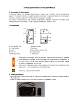
Nomenclature and functions
RL-H3C / RL-H3CL
RL-H3C / RL-H3CL
1
2
3
4
5
6
7
8
9
10
11
12
RL-H3C_CL_CS.fm Page 8 Monday, June 12, 2006 9:47 AM

9
1. Manual mode ON (Red LED)
Auto leveling does not function.
2. Height alert OFF (Red LED)
Height alert does not function.
3. Height alert OFF switch
OFF:Push twice continuously.
ON:Push once.
4. Manual mode ON switch
ON:Push twice continuously.
OFF:Push once.
5. Handle
6. Protective glass
7. Rotary head
Laser beam emits from here.
8. Battery power (Red LED)
Blinking: The power is low, but laser is still usable. (Blinking continues for one
minute.)
On Solid: Dead batteries. Replace the batteries with new ones. (The lamp is solid
for five minutes, then turned off automatically.)
9. Auto leveling (Green LED)
Blinking slowly: Auto levelling is in process.
Blinking quickly: Auto levelling is almost complete.
On Solid: Auto levelling is complete.
10. Power switch
Turn the instrument ON or OFF.
11. Battery door knob
12. Battery door
Height alert function
(Safety lock system)
When auto-leveling and height alert function are active, after the laser beam
emits for one minute, this function prevents the instrument from operating if it
is disturbed. This insures accurate control. If the unit is disturbed, all lamps will
blink except battery power lamp. The elevation (height of instrument) should
be verified and re-established if necessary. This function is not active in the
manual mode.
Note
In manual mode
•Auto-leveling function is not active.
•Height alert function is not active.
RL-H3C_CL_CS.fm Page 9 Monday, June 12, 2006 9:47 AM

10
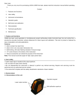
LS-70B/70C (Laser Sensor)
1. On-Grade Index
2. Beam receiving window
Turn the beam receiving window side towards RL-H3C to detect the laser beam.
3. Indicator
Detect the on-grade position “---” by moving the Laser Sensor up and down. Directional
arrows and audio signals assist in locating the on-grade position as the laser strikes the
beam receiving window. (Top of Laser Sensor is 40mm (1 9/16")from on-grade index
for offset marking.)
LS-70B:The indicators are located on front and back sides of the instrument.
LS-70C:The indicator is located only on front side.
4. On-Grade precision switch
Two on-grade precision options are available, normal precision and high precision. By
pressing this switch, the precision options are switched alternately. Confirm the preci-
sion choice by the indicator. (Normal precision is the default setting each time the sen-
sor is turned on.
See LS-70B/70C Indicator diagram below.)
5. Power switch
The power switch turns ON or OFF by pressing. If the power switch is turned ON, all
signs will be displayed on the indicator for a second with a beep sound.
6. Buzzer speaker
7. Buzzer sound switch
Volume of the sensor buzzer can be alternately switched to LOW/LOUD/OFF by press-
ing the switch.
Auto shut off function
The power will be turned off automatically if no laser beam is detected for approx.
30 min. (To turn on the laser sensor, press the power switch again.)
(1 9/16")
1
2
3
4
5
6
7
RL-H3C_CL_CS.fm Page 10 Monday, June 12, 2006 9:47 AM

11
RL-H3CS
RL-H3CS
1
2
3
4
5
6
7
8
9
10
11
12
13
14
15
RL-H3C_CL_CS.fm Page 11 Monday, June 12, 2006 9:47 AM

12
1. Slope lamp (Green LED)
Red: Error.
2. Slope key
Tilts beam plane in direction of arrow.
3. Manual mode ON (Red LED)
Auto leveling does not function.
4. Height alert OFF (Red LED)
Height alert does not function.
5. Height alert OFF switch
OFF: Push twice continuously.
ON: Push once.
6. Manual mode ON switch
OFF: Push twice continuously.
ON: Push once.
7. Handle
8. Sight
9. Protective glass
10. Rotary head
Laser beam emits from here.
11. Battery power (Red LED)
Blinking: The power is low, but laser is still usable. (Blinking continues for one
minute.)
On Solid: Dead batteries. Replace the batteries with new ones. (The lamp is solid
for five minutes, then turned off automatically.)
12. Auto leveling (Green LED)
Blinking slowly: Auto levelling is in process.
Blinking quickly: Auto levelling is almost complete.
On Solid: Auto levelling is complete.
13. Power switch
Turn the instrument ON or OFF.
14. Battery door knob
15. Battery door
Height alert function
(Safety lock system)
When auto-leveling and height alert function are active, after the laser beam
emits for one minute, this function prevents the instrument from operating if it
is disturbed. This insures accurate control. If the unit is disturbed, manual
mode ON lamp, height alert OFF lamp and auto leveling lamp will blink simul-
taneously. The elevation (height of instrument) should be verified and re-
established if necessary. This function is not active in the manual mode.
Note
In manual mode
•Auto-leveling function is not active.
•Height alert function is not active.
•Setting slope function is not active.
RL-H3C_CL_CS.fm Page 12 Monday, June 12, 2006 9:47 AM

13
LS-70B (Laser Sensor)
1. On-Grade Index
2. Beam receiving window
Turn the beam receiving window side towards RL-H3CS to detect the laser beam.
3. Indicator
Detect the on-grade position “---” by moving the Laser Sensor up and down. Direc-
tional arrows and audio signals assist in locating the on-grade position as the laser
strikes the beam receiving window. (Top of Laser Sensor is 40mm (1 9/16")from on-
grade index for offset marking.)
LS-70B:The indicators are located on front and back sides of the instrument.
4. On-Grade precision switch
Two on-grade precision options are available, normal precision and high precision.
By pressing this switch, the precision options are switched alternately. Confirm the
precision choice by the indicator. (Normal precision is the default setting each time
the sensor is turned on. See LS-70B/70C Indicator diagram below.)
5. Power switch
The power switch turns ON or OFF by pressing. If the power switch is turned ON, all
signs will be displayed on the indicator for a second with a beep sound.
6. Buzzer speaker
7. Buzzer sound switch
Volume of the sensor buzzer can be alternately switched to LOW/LOUD/OFF by
pressing the switch.
Auto shut off function
The power will be turned off automatically if no laser beam is detected for
approx. 30 min. (To turn on the laser sensor, press the power switch again.)
(1 9/16")
12
3
4
5
6
7
RL-H3C_CL_CS.fm Page 13 Monday, June 12, 2006 9:47 AM

14
BATTERY REPLACEMENT
1 Remove the battery cover by turning battery cover knob to “OPEN” side.
2 Remove the batteries by pulling out the slide plate.
3 Install the new batteries referring to the illustration on the battery cover.
*1, *2, *3
4 Install the battery cover. By using a coin, tighten the battery cover knob to
“CLOSE” side until the knob does not turn.*4
*1 Replace all 4 batteries with new ones at the same time. Do not mix used and new bat-
teries, and do not mix different types of batteries together.
*2 Use alkaline dry cells. (Dry cells for movement confirmation are packed in shipment.)
Nickel hydrogen dry cells and nickel cadmium dry cells can be used too, but the oper-
ating time is different from the time of alkaline dry cells.
*3 Generally, performances of dry cell deteriorate temporarily in low temperature, but re-
cover in normal temperature.
*4 It is important to use a coin or other tool to make sure cover is firmly closed to seal out-
water.
Laser Sensor
1 Press the lid in the direction of the arrow to lift.
2 Remove the battery and replace with a new 9v alkaline battery.
3 Press the lid down and click to close.
Slide plate
RL-H3C_CL_CS.fm Page 14 Monday, June 12, 2006 9:47 AM

15
EXAMPLES OF TYPICAL USE
154
152
150
153
151
138
136
134
132
139
137
135
133
131
131
149
147
148
146
g n k c d q | U
Clamp Knob
Laser Sensor Holder
Laser Sensor
Using Laser Sensor On Rod
Level Vial
RL-H3C_CL_CS.fm Page 15 Monday, June 12, 2006 9:47 AM

16
Operation
HOW TO OPERATE
1 Set the instrument to the tripod or smooth surface.
2 Make sure instrument is roughly level (± 3°).
3 Press power switch (ON).
4 Press power switch on laser sensor (ON).
5 Select the precision mode by pressing the On-Grade precision switch.
6 Locate the on-grade position “---” by moving the laser sensor up and down.
1 Mark the position of On-Grade index.
(Top of the Laser Sensor is 40mm [1 9/16"] from index for offset marking.)
L
S
-7
0B
I
n
di
cator
High precision mode
Normal precision mode
Battery remaining display
Below grade indicator
Move the sensor up.
Audio signal:Lower pitch, slower frequency
Above grade indicator
Move the sensor down.
Audio signal:High pitch, frequent beep
When using the
Laser Sensor with
other select Top-
con lasers, these
symbols alert user
if laser batteries
are low or if laser
has been dis-
turbed. These
symbols are not
active when used
with the Rotating
On-Grade position
Audio signal:Continuous beep sound
RL-H3C_CL_CS.fm Page 16 Monday, June 12, 2006 9:47 AM

17
RL-H3CS
Aligning Direction of Slope
When using the laser to set the slope, the laser must be properly aligned so
the slope axis of the laser beam is parallel to the desired direction of slope.
The sight on top of the instrument is calibrated to the slope axis of the laser
beam. Follow the steps below to align the laser to the desired direction of
slope:
1 Establish a target line parallel to desired direction of slope.
2 Set up the laser over this line (drop a plumb bob from the tripod mounting
screw).
3 Rough align the instrument to the direction of slope. Make sure it is properly
oriented for the slope to be set.
4 Using the sight, position the instrument so the sight is centered on the tar-
get. (see illustration below)
[Setting slope]
Operating procedure
(Setting slope)
Key
operation
Lamp display
(Refer to the illustration above)
1 Press Power switch ON.
You can set the slope after auto-
leveling is completed.
Power
switch
During auto-leveling: Lamp B (Green) blinks.
After auto-leveling is completed: Lamp B
(Green) lights.
2 Press either Slope key once. The
laser beam begins to move in the
direction of the arrow on the key.
After auto-
leveling is
completed.
Slope key
Lamp E (Green) blinks quickly.
3 Press Slope key again to stop the
laser beam.
Slope key Lamp E (Green) lights.
4 Press Slope key to fine adjust the
slope.
Beam movement begins slowly,
then increases depending on how
long the Slope key is pressed.
The blinking speed of the lamp
provides a visual indication of the
beam movement speed.
Slope key When Slope key is not pressed:
Lamp E (Green) lights.
Slope key Lamp E (green) Beam movement
Press for a shorter time :Blinks slowly :Moves
slowly
Å@Å@ ↓Å@Å@Å@Å@ Å@Å@Å@Å@ ↓ ↓
Press for a longer time :Blinks quickly :Moves
quickly
5 Press Power switch OFF to can-
cel the slope setting.
Power
switch
All lamps are OFF.
Target
RL-H3C_CL_CS.fm Page 17 Monday, June 12, 2006 9:47 AM

18
Operating procedure
(Recalling slope)
Key
operation
Lamp display
(Refer to the illustration above)
1 To recall the previous slope setting
(the setting before power was
OFF), press Power switch ON
while pressing either the right or
left Slope key. The slope can then
be adjusted as described in step 4
above.
• When the Power switch is ON
without the Slope key pressed, the
laser beam will return to level.
Slope key
+
Power
switch
When Slope key is not pressed: Lamp E
(Green) lights.
Slope key Lamp E (green) Beam move-
ment
Press for a shorter time : Blinks slowly :
Moves slowly
Å@Å@ ↓Å@Å@Å@Å@ Å@Å@Å@Å@ ↓ ↓
Press for a longer time : Blinks quickly :
Moves quickly
A
B
D
C
Manual mode can be activated while the slope is
set.
For information about Manual mode ON/OFF,
refer to "NOMENCLATURE AND FUNCTIONS".
Check the beam often during slope use for slope
accuracy. Check instrument calibration periodi-
cally (see below).
E
RL-H3C_CL_CS.fm Page 18 Monday, June 12, 2006 9:47 AM

19
Checks and adjustments
1 Checking and adjusting calibration
Horizontal calibration of the laser beam can be checked by the user.
[Checking]
1 Set up a tripod approx. 50m (160ft) from a wall. Mount the instrument on the
tripod, facing the X1 side toward the wall.
2 Turn the instrument on and allow auto-leveling to complete.
3 Put the laser sensor in fine detection mode by pressing the On-Grade preci-
sion switch.
4 By using the laser sensor, mark the center position of laser beam on the
wall. (X1)
5 Turn off the instrument.
Loosen the tripod screw, rotate the instrument 180 degrees and re-secure it
on the tripod. The X2 side of the instrument faces toward the wall.
When rotating the instrument, avoid changing the height.
6 Turn the unit on again and allow auto-leveling to complete.
7 By using the laser sensor, mark the center position of laser beam on the
wall. (X2)
8 If the difference value of marked two laser beam heights (difference value of
X1 and X2) are less than the value specified in the next table, adjustments
are not needed. If the difference value is greater than the value specified in
the table, adjust the instrument as described below. *
9 Check the X1 (handle) side as the same way.
X1
X2
*If the difference value is
greater than 60mm (2 3/8
inches), contact your Topcon
dealer.
Y1
Y2
Type Value
RL-H3C 7 mm
RL-H3CL 5 mm
RL-H3CS 7 mm
RL-H3C_CL_CS.fm Page 19 Monday, June 12, 2006 9:47 AM

20
[To calibrate the X axis ]
1 Face the X1 side of the instrument (panel side) toward a wall, press the
Power switch while pressing the height alert OFF switch.
Then the height alert OFF lamp will light, and manual mode ON lamp will
blink.
2 Press the height alert OFF switch to calibrate the X axis. The manual mode
ON lamp will light. When auto-leveling finishes, the laser beam will emit.
3 Using the laser sensor, mark the on-grade height of laser beam on a wall.
4 Rotate the instrument 180 degrees to face X2 side toward a wall.
5 In the same way as step 3 , mark the on-grade height of laser beam on a
wall.
6 By pressing the manual mode ON switch (laser beam moves up), or Power
switch (laser beam moves down), adjust the on-grade height of the beam
until it is precisely centered between the marks made in steps 3 and 5 .
7 Press the height alert OFF switch to memorize the new laser beam calibra-
tion. The height alert OFF lamp will blink. Power will shut off automatically
when the calibration memorization is complete.
[To calibrate the Y axis ]
1 Face the Y1 side of the instrument (handle side) toward a wall, press the
Power switch while pressing the height alert OFF switch.
Then the height alert OFF lamp will light, and manual mode ON lamp will
blink.
2 Press the Power switch again. The auto leveling lamp will light.
3 Press the height alert OFF switch to calibrate the Y axis. The auto leveling
lamp will light.
4 Using the laser sensor, mark the on-grade height of laser beam on a wall.
5 Rotate the instrument 180 degrees to face Y2 side toward a wall.
6 In the same way as step 4 , mark the on-grade height of laser beam on a
wall.
7 By pressing the manual mode ON switch (laser beam moves up), or Power
switch (laser beam moves down), adjust the on-grade height of the beam
until it is precisely centered between the marks made in steps 4 and 6.
8 Press the height alert OFF switch to memorize the new laser beam calibra-
tion. The height alert OFF lamp will blink. Power will shut off automatically
when the calibration memorization is complete.
To discontinue calibration the instrument, press the Power switch while
pressing the height alert OFF switch.
When calibration is memorizing, if the height alert lamp continues to blink
quickly and power does not shut-off automatically, please contact your local
Topcon dealer.
RL-H3C_CL_CS.fm Page 20 Monday, June 12, 2006 9:47 AM
Page is loading ...
Page is loading ...
Page is loading ...
Page is loading ...
Page is loading ...
Page is loading ...
Page is loading ...
Page is loading ...
/