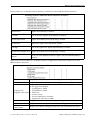
Comtrol DeviceMaster UP – EtherNet/IP User guide
- Category
- Software
- Type
- User guide
This manual is also suitable for

EtherNet
®
/IP User Guide

Trademark Notices
Comtrol, DeviceMaster, and PortVision are registered trademarks of Comtrol Corporation.
ControlLogix, PLC-5 and Rockwell Automation are registered trademarks of Rockwell Automation.
MicroLogix, RSLinx, RSLogix 5, RSLogix 500, RSLogix 5000 and SLC are trademarks of Rockwell
Automation.
PLC is a registered trademark of Allen-Bradley Company, Inc.
Ethernet is a registered trademark of Digital Equipment Corporation, Intel, and Xerox Corporation.
Portions of SocketServer are copyrighted by GoAhead Software, Inc. Copyright © 2001. GoAhead Software,
Inc. All Rights Reserved.
Windows is a registered trademark of Microsoft Corporation in the United States and/or other countries.
Other product names mentioned herein may be trademarks and/or registered trademarks of their respective
owners.
Thirteenth Edition, April 6, 2018
Copyright © 2005-2018. Comtrol Corporation.
All Rights Reserved.
Comtrol Corporation makes no representations or warranties with regard to the contents of this document or
to the suitability of the Comtrol product for any particular purpose. Specifications subject to change without
notice. Some software or features may not be available at the time of publication. Contact your reseller for
current product information.
DocumentNumber:2000424RevM
PatentsPending

DeviceMaster EtherNet/IP User Guide: 2000424 Rev. M Table of Contents - iii
Table of Contents
Chapter 1. Introduction........................................................................................................9
1.1. Product Name Change Notification................................................................................................... 9
1.2. Audience ................................................................................................................................................... 9
1.3. Product Overview ................................................................................................................................ 10
1.4. EtherNet/IP Firmware ........................................................................................................................ 10
1.4.1. Locating the Latest Software and Documents .............................................................................. 10
1.4.2. Data Type Definitions .................................................................................................................... 11
1.4.3. Terms and Definitions.................................................................................................................... 12
1.4.4. EtherNet/IP System Architecture.................................................................................................. 12
1.4.5. Filtering and Data Extraction Functionality (Patent Pending)................................................... 13
1.5. EtherNet/IP Application Setup ......................................................................................................... 13
Chapter 2. Data Transfer....................................................................................................15
2.1. Data Message Format .......................................................................................................................... 15
2.1.1. Receive Data Message .................................................................................................................... 15
2.1.2. Transmit Data Message ................................................................................................................. 16
2.2. Data Transfer Methods ....................................................................................................................... 17
2.2.1. Receive Data Methods .................................................................................................................... 17
2.2.1.1. Polling-PLC Requests Data .................................................................................................. 17
2.2.1.2. Write-to-Tag/File Gateway Writes Data Directly Into PLC Memory................................. 17
2.2.1.3. Class 1 Connection (Input Only)-PLC and Gateway Utilize an I/O Connection ............... 18
2.3. Transmit Data Methods ...................................................................................................................... 18
2.3.1. PLC-Writes...................................................................................................................................... 18
2.3.2. Class 1 Connection (Input & Output) - PLC and DeviceMaster Utilize an I/O Connection....... 19
Chapter 3. Programming Interface..................................................................................21
3.1. Overview................................................................................................................................................. 21
3.1.1. ControlLogix Family....................................................................................................................... 21
3.1.2. PLC-5/SLC or MicroLogix .............................................................................................................. 21
3.1.3. What is EtherNet/IP? ..................................................................................................................... 22
3.2. EtherNet/IP Interface Profile (ControlLogix) ...............................................................................22
3.2.1. Serial Port Configuration Object Definition (70 Hex) .................................................................. 22
3.2.1.1. Class Attributes..................................................................................................................... 22
3.2.1.2. Instance Attributes ............................................................................................................... 22
3.2.1.3. Common Services .................................................................................................................. 27
3.2.1.4. Instance Attribute Definitions.............................................................................................. 27
3.2.2. Serial Port Data Transfer Object Definition (71 Hex) .................................................................. 35
3.2.2.1. Class Attributes..................................................................................................................... 35
3.2.2.2. Instance Attributes ............................................................................................................... 35
3.2.2.3. Common Services .................................................................................................................. 35
3.2.2.4. Instance Attribute Definitions.............................................................................................. 36
3.2.3. Serial Port Statistics Object Definition (72 Hex) .......................................................................... 37
3.2.3.1. Class Attributes..................................................................................................................... 37
3.2.3.2. Instance Attributes ............................................................................................................... 37
3.2.3.3. Common Services .................................................................................................................. 37
3.2.3.4. Instance Attribute Definitions.............................................................................................. 38

iv - Table of Contents DeviceMaster EtherNet/IP User Guide: 2000424 Rev. M
Table of Contents
3.2.4. Socket Port Configuration Object Definition (73 Hex) ................................................................. 39
3.2.4.1. Class Attributes..................................................................................................................... 39
3.2.4.2. Instance Attributes ............................................................................................................... 39
3.2.4.3. Common Services .................................................................................................................. 45
3.2.4.4. Instance Attribute Definitions.............................................................................................. 45
3.2.5. Socket Port Data Transfer Definition Object (74 Hex)................................................................. 54
3.2.5.1. Class Attributes..................................................................................................................... 54
3.2.5.2. Instance Attributes ............................................................................................................... 54
3.2.5.3. Common Services .................................................................................................................. 54
3.2.5.4. Instance Attribute Definitions.............................................................................................. 55
3.2.6. Assembly Object (For Class 1 Interface) ....................................................................................... 56
3.2.6.1. Class Attributes..................................................................................................................... 56
3.2.6.2. Instance Attributes ............................................................................................................... 56
3.2.6.2.1. Instance Attribute Definitions: Attribute 3-Request/Write Data.................................56
3.2.6.2.2. Instance Attribute Definitions: Attribute 4-Data Length.............................................56
3.2.6.3. Common Services .................................................................................................................. 57
3.2.6.4. Instance Definitions (1-Port Models) ...................................................................................57
3.2.6.4.1. Assembly Input Instances...............................................................................................57
3.2.6.4.2. Assembly Output Instances............................................................................................57
3.2.6.5. Instance Definitions (2-Port Models) ...................................................................................58
3.2.6.5.1. Assembly Input Instances...............................................................................................58
3.2.6.5.2. Assembly Output Instances............................................................................................58
3.2.6.6. Instance Definitions (4-Port Models) ...................................................................................59
3.2.6.6.1. Assembly Input Instances...............................................................................................59
3.2.6.6.2. Assembly Output Instances............................................................................................60
3.2.6.7. Overview of Assembly Interface ........................................................................................... 60
3.2.6.7.1. 1-Port Gateways ..............................................................................................................61
3.2.6.7.2. 2-Port Gateways ..............................................................................................................61
3.2.6.7.3. 4-Port Gateways ..............................................................................................................62
3.2.6.8. Grouping of Assembly Instances .......................................................................................... 62
3.2.6.8.1. 1-Port Models - Assembly Controller Access .................................................................63
3.2.6.8.2. 2-Port Models - Assembly Controller Access .................................................................63
3.2.6.8.3. 4-Port Models - Assembly Controller Access .................................................................65
3.2.7. Informational Objects..................................................................................................................... 66
3.2.7.1. Identity Object (01 Hex, 1 instance)..................................................................................... 66
3.2.7.1.1. Class Attributes...............................................................................................................66
3.2.7.1.2. Instance Attributes .........................................................................................................66
3.2.7.1.3. Status Word.....................................................................................................................67
3.2.7.1.4. Common Services ............................................................................................................68
3.2.7.2. Message Router Object (02 Hex) .......................................................................................... 69
3.2.7.2.1. Class Attributes...............................................................................................................69
3.2.7.2.2. Instance Attributes .........................................................................................................69
3.2.7.2.3. Common Services ............................................................................................................69
3.2.8. Connection Manager Object (06 Hex)............................................................................................ 69
3.2.8.1. Class Attributes Object (06 Hex).......................................................................................... 69
3.2.8.2. Instance Attributes (06 Hex) ................................................................................................ 70
3.2.8.3. Common Services Object (06 Hex) ....................................................................................... 70
3.2.9. Port Object (F4 Hex - 1 Instance) .................................................................................................. 71
3.2.9.1. Class Attributes..................................................................................................................... 71
3.2.9.2. Instance Attributes ............................................................................................................... 71
3.2.9.3. Common Services .................................................................................................................. 73
3.2.10. TCP Object (F5 Hex - 1 Instance) ................................................................................................ 73
3.2.10.1. Class Attributes................................................................................................................... 73
3.2.10.2. Instance Attributes ............................................................................................................. 73
3.2.10.3. Common Services ................................................................................................................ 74
3.2.11. Ethernet Link Object (F6 Hex) .................................................................................................... 75
3.2.11.1. Class Attributes................................................................................................................... 75
3.2.11.2. Instance Attributes ............................................................................................................. 75
3.2.11.3. Common Services ................................................................................................................ 77

DeviceMaster EtherNet/IP User Guide: 2000424 Rev. M Table of Contents - v
Table of Contents
3.2.12. PCCC Object (67 Hex) .................................................................................................................. 77
3.2.12.1. Class Attributes................................................................................................................... 77
3.2.12.2. Instance Attributes ............................................................................................................. 77
3.2.12.3. Instances.............................................................................................................................. 77
3.2.12.4. Common Services ................................................................................................................ 77
3.2.12.5. Message Structure for Execute PCCC ............................................................................... 77
3.3. PLC-5/SLC and MicroLogix Interfaces............................................................................................ 79
3.3.1. Requirements.................................................................................................................................. 80
3.3.1.1. SLC 5/05................................................................................................................................. 80
3.3.1.2. PLC-5 ..................................................................................................................................... 80
3.3.2. Messages ......................................................................................................................................... 81
3.3.3. DeviceMaster File Addressing ....................................................................................................... 81
3.3.4. Receive Data Message .................................................................................................................... 82
3.3.5. Transmit Data Message ................................................................................................................. 83
3.3.6. Sequence Number Messages .......................................................................................................... 84
3.3.7. Retrieve Statistics Message ........................................................................................................... 84
3.3.8. Receive Communication Methods.................................................................................................. 86
3.3.8.1. Unsolicited - Write to File Receive Method ......................................................................... 86
3.3.8.2. Unsolicited - Write to File Synced Receive Method ............................................................ 86
3.3.8.3. Polling Receive Method......................................................................................................... 87
Chapter 4. Embedded Configuration Pages...................................................................89
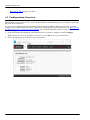
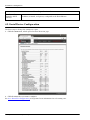
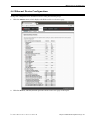
4.1. Configuration Overview ..................................................................................................................... 90
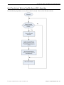
4.1.1. Serial Device - Configuration Overview ........................................................................................ 91
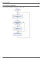
4.1.2. Ethernet Device - Configuration Overview ................................................................................... 94
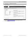
4.2. Embedded Web Pages Overview....................................................................................................... 97
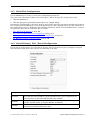
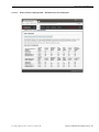
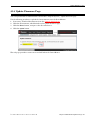
4.3. Serial Device Configuration .............................................................................................................. 98
4.3.1. Serial Port Configuration ............................................................................................................... 99
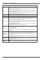
4.3.2. Serial Settings | Port | Serial Configuration............................................................................... 99
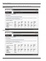
4.3.3. Serial | Serial Settings | SerialPacket Identification................................................................ 101
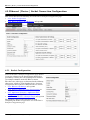
4.4. Ethernet Device Configuration....................................................................................................... 103
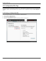
4.5. Ethernet | Device | Socket Connection Configuration ............................................................ 104
4.5.1. Socket Configuration .................................................................................................................... 104
4.5.2. Device Socket Packet ID Settings................................................................................................ 106
4.6. Common Configuration Areas (Serial or Ethernet Device) ..................................................... 108
4.6.1. Ethernet/IP Settings..................................................................................................................... 108
4.6.2. Filtering/Data Extraction Configuration..................................................................................... 111
4.6.3. Application Interface | Application TCP Configuration ............................................................ 115
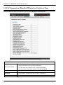
4.7. EtherNet/IP Class 1 Interface Pages.............................................................................................. 116
4.7.1. Class1 Overview Pages................................................................................................................. 116
4.7.1.1. Active Class1 Configuration ............................................................................................... 116
4.7.1.1.1. Active Class1 Configuration - All Interfaces Set to Defaults......................................117
4.7.1.1.2. Active Class1 Configuration – Only Serial Ports Set to Defaults ..............................118
4.7.1.1.3. Active Class1 Configuration – Only TCP/IP Sockets Set to Defaults ........................119
4.7.1.2. Default Class1 Configurations ........................................................................................... 120
4.7.1.2.1. All Serial Port and TCP/IP Socket Interface Default..................................................120
4.7.1.2.2. Only Serial Port(s) Default ...........................................................................................121
4.7.1.2.3. Only TCP/IP Socket(s) Default.....................................................................................121
4.8. Class1 Interface Specific Pages ...................................................................................................... 122
4.8.1. Class1 Interface Starting at Serial Port 1 (Example)................................................................. 122
4.8.2. Class Interface Starting at Serial Port 2 (Example)................................................................... 123
4.8.3. Class 1 Interface Starting at TCP/IP Device 1 (Example) ......................................................... 123
4.8.4. Class 1 Interface Starting at TCP/IP Devcie 2 (Example) ......................................................... 124
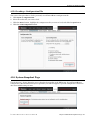
4.9. Network Configuration Page........................................................................................................... 125
4.9.1. Network Configuration Page Options ......................................................................................... 125
4.9.2. Changing the Network Configuration ......................................................................................... 126
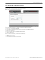
4.10. Password Configuration Page....................................................................................................... 127

vi - Table of Contents DeviceMaster EtherNet/IP User Guide: 2000424 Rev. M
Table of Contents
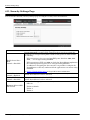
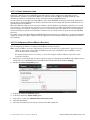
4.11. Security Settings Page .................................................................................................................... 128
4.11.1. Client Authentication ................................................................................................................. 129
4.11.2. Configuring DeviceMaster Security........................................................................................... 129
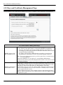
4.12. Keys and Certificate Management Page..................................................................................... 130
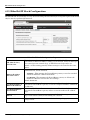
4.13. EtherNet/IP Stack Configuration................................................................................................. 132
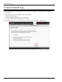
4.14. Update Firmware Page ................................................................................................................... 133
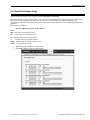
4.15. Configuration File Page.................................................................................................................. 134
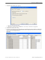
4.15.1. Saving a Configuration File ....................................................................................................... 134
4.15.2. Loading a Configuration File ..................................................................................................... 135
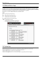
4.16. System Snapshot Page .................................................................................................................... 135
4.17. Restore Defaults Page ..................................................................................................................... 136
4.18. Reboot Page ....................................................................................................................................... 137
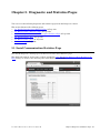
Chapter 5. Diagnostic and Statistics Pages .................................................................139
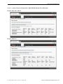
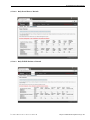
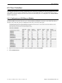
5.1. Serial Communication Statistics Page.......................................................................................... 139
5.2. Ethernet Device Statistics Page ..................................................................................................... 142
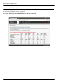
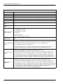
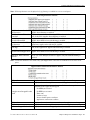
5.3. PLC Diagnostics (EtherNet/IP Interface Statistics) Page ........................................................ 144
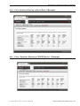
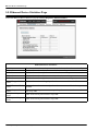
5.4. Serial Interface Logs ......................................................................................................................... 147
5.5. Ethernet Device Logs ........................................................................................................................ 148
5.6. System Log ........................................................................................................................................... 148
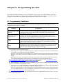
Chapter 6. Programming the PLC..................................................................................149
6.1. Programming Guidelines ................................................................................................................. 149
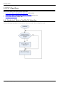
6.2. PLC Algorithms................................................................................................................................... 150
6.2.1. Unsolicited - Write-to-Tag/File PLC Algorithm .......................................................................... 150
6.2.2. Unsolicited - Write-to-Tag/File-Synced PLC Algorithm ............................................................. 151
6.2.3. Polling PLC Algorithm ................................................................................................................. 152
6.3. Class 1 Interface ................................................................................................................................. 153
6.3.1. Configuring an I/O Ethernet Module........................................................................................... 153
6.4. ControlLogix PLC Programming Example Instructions .......................................................... 157
6.4.1. What is RSLogix 5000?................................................................................................................. 157
6.4.2. Requirements................................................................................................................................ 157
6.4.3. loopbackExampleTagWrite.L5K .................................................................................................. 158
6.4.4. loopbackExampleTagWriteSynced.L5K ...................................................................................... 159
6.4.5. loopbackExamplePolling.L5K ...................................................................................................... 160
6.4.6. Configuring the DeviceMaster for the RSLogix 5000 Example Programs Using the Web Page ...
161
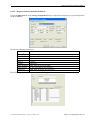
6.4.7. RSLogix 5000 Screen Examples................................................................................................... 162
6.4.7.1. Transmit Data to the DeviceMaster................................................................................... 162
6.4.7.2. Send Configuration to DeviceMaster ................................................................................. 163
6.4.7.3. Request Data from DeviceMaster ...................................................................................... 165
6.4.7.4. Send Consumed Sequence Number to DeviceMaster ....................................................... 166
6.4.7.5. Request Statistics from DeviceMaster ............................................................................... 167
6.4.7.6. Communication Window for all Messages sent to the DeviceMaster .............................. 168
6.4.8. Modifying an RSLogix 5000 PLC Program Example (Older Versions) ..................................... 168
6.5. SLC or MicroLogix PLC Programming Example Instructions................................................ 170
6.5.1. What is RSLogix 500?................................................................................................................... 170
6.5.2. Requirements................................................................................................................................ 170
6.5.3. Example Program Considerations ............................................................................................... 171
6.5.3.1. lpbkExampleSlcMsgPollRS500 - SLC PLC........................................................................ 171
6.5.3.2. lpbkExamplePlc5MsgPollRS500 - SLC PLC ..................................................................... 171
6.5.3.3. lpbkExampleSlcMsgFileRS500 - SLC PLC........................................................................ 171
6.5.3.4. lpbkExampleSlcMsgFileSyncRS500 - SLC PLC................................................................ 172
6.5.3.5. LPBKEXAMPLESLCMSGFILERS500_MICROLGX - MicroLogix PLC ......................... 172
6.5.3.6. LPBKEXAMPLESLCMSGPOLLRS500_MICROLGX - MicroLogix PLC........................ 172

DeviceMaster EtherNet/IP User Guide: 2000424 Rev. M Table of Contents - vii
Table of Contents
6.5.4. Configure the DeviceMaster for the RSLogix 500 Example Program - SLC PLC .................... 173
6.5.5. Configure and Run the RSLogix 500 Example Program - SLC PLC ......................................... 174
6.5.6. RSLogix 500 Screen Examples - SLC PLC.................................................................................. 177
6.5.6.1. Setting up Processor and Ethernet (Channel 1)................................................................ 177
6.5.6.2. SLC Typed Read - Receive Data Message - SLC PLC....................................................... 180
6.5.6.3. SLC Typed Write - Transmit Data Message - SLC PLC................................................... 181
6.5.6.4. SLC Typed Read - Retrieve Statistics Message - SLC PLC.............................................. 182
6.5.6.5. SLC Typed Write - Set Receive Produced Sequence Number Message - SLC PLC......... 183
6.5.6.6. SLC Typed Write - Set Transmit Produced Sequence Number Message - SLC PLC...... 184
6.5.6.7. PLC-5 Typed Read - Receive Data Message - SLC PLC ................................................... 185
6.5.6.8. PLC-5 Typed Write - Transmit Data Message - SLC PLC ............................................... 186
6.5.6.9. PLC-5 Typed Read - Retrieve Statistics Message - SLC PLC .......................................... 187
6.5.6.10. PLC-5 Typed Write - Set Receive Produced Sequence Number Message - SLC PLC ... 188
6.5.6.11. PLC-5 Typed Write - Set Transmit Produced Sequence Number Message - SLC PLC 189
6.5.6.12. MultiHop Screen ............................................................................................................... 189
6.5.7. Configuring and Running the MicroLogix RSLogix 500 Example Program ............................. 190
6.5.7.1. Receive Sequence Number Init Message ........................................................................... 192
6.5.7.2. Transmit Sequence Number Init Message ........................................................................ 193
6.5.7.3. Transmit Data Message...................................................................................................... 194
6.5.7.4. Receive Data Message......................................................................................................... 195
6.5.7.5. MultiHop Screen ................................................................................................................ 196
6.6. PLC-5 PLC Programming Example Instructions........................................................................ 197
6.6.1. What is RSLogix 5?....................................................................................................................... 197
6.6.2. Requirements................................................................................................................................ 197
6.6.3. Example Program Considerations ............................................................................................... 198
6.6.4. lpbkExampleSlcMsgPollRS5........................................................................................................ 198
6.6.5. lpbkExamplePlc5MsgPollRS5...................................................................................................... 198
6.6.6. lpbkExamplePlc5MsgFileRS500.................................................................................................. 198
6.6.7. lpbkExamplePlc5MsgFileSyncRS5.............................................................................................. 199
6.6.8. Configure the DeviceMaster for the RSLogix 5 Program ........................................................... 199
6.6.9. Configure and Run the Example RSLogix 5 Program................................................................ 201
6.6.10. RSLogix 5 Screen Examples....................................................................................................... 203
6.6.10.1. Requirements .................................................................................................................... 203
6.6.10.2. Setting up Processor and Ethernet Channel ................................................................... 203
6.6.10.3. SLC Typed Read - Receive Data Message........................................................................ 205
6.6.10.4. SLC Typed Write - Transmit Data Message.................................................................... 206
6.6.10.5. SLC Typed Read - Retrieve Statistics Message............................................................... 207
6.6.10.6. SLC Typed Write - Set Receive Produced Sequence Number Message ......................... 208
6.6.10.7. SLC Typed Write - Set Transmit Produced Sequence Number Message ...................... 209
6.6.10.8. PLC-5 Typed Read - Receive Data Message .................................................................... 210
6.6.10.9. PLC-5 Typed Write - Transmit Data Message ................................................................ 211
6.6.10.10. PLC-5 Typed Read - Retrieve Statistics Message ......................................................... 212
6.6.10.11. PLC-5 Typed Write - Set Receive Produced Sequence Number Message .................... 213
6.6.10.12. PLC-5 Typed Write - Set Transmit Produced Sequence Number Message ................. 214
6.6.10.13. MultiHop Screen ............................................................................................................. 214
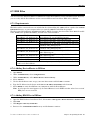
6.7. EDS Files .............................................................................................................................................. 215
6.7.1. Requirements................................................................................................................................ 215
6.7.2. Adding DeviceMaster to RSLinx.................................................................................................. 215
6.7.3. Adding EDS Files to RSLinx........................................................................................................ 215
6.7.4. Troubleshooting RSLinx............................................................................................................... 216
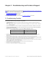
Chapter 7. Troubleshooting and Technical Support .................................................217
7.1. Troubleshooting Checklist .............................................................................................................. 217
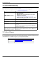
7.2. General Troubleshooting.................................................................................................................. 218
7.3. Technical Support.............................................................................................................................. 218

viii - Table of Contents DeviceMaster EtherNet/IP User Guide: 2000424 Rev. M
Table of Contents

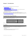
DeviceMaster EtherNet/IP User Guide: 2000424 Rev. M Chapter 1. Introduction - 9
Chapter 1. Introduction
This User Guide provides detailed information about the following topics:
• Programming Interface
on Page 21
• Embedded Configuration Pages
on Page 89
• Diagnostic and Statistics Pages
on Page 139
The EtherNet/IP Hardware Installation and Configuration Guide
provides the following information:
• Connecting the hardware and devices
• Programming the DeviceMaster UP or DeviceMaster EIP IP address,
• Uploading EtherNet/IP firmware
The EtherNet/IP Interface Configuration Quick Start provides embedded web page configuration procedures
if you have Read-only or read/write devices, which provides procedures for your devices.
See Locating the Latest Software and Documents
on Page 10 to locate the latest firmware, documentation, and
tools.
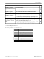
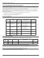
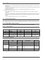
1.1. Product Name Change Notification
Comtrol has implemented a product name change for the DeviceMaster UP 2-port DIN rail models that align
with our new 1-port and 4-port DIN rail model names.
Note: Please note that the form, fit, and function of the DeviceMaster has not changed - only the name.
In this manual, the DeviceMaster UP or DeviceMaster EIP is simply referred to as the DeviceMaster.
1.2. Audience
The primary audience of this document is the person responsible for installing the DeviceMaster and
programming the PLC. This guide assumes you are familiar with the following topics:
• Windows operating system
• EtherNet/IP
• Allen-Bradley ControlLogix family, PLC-5, SLC or MicroLogix PLCs
• RSLogix 5000, RSLogix 500 or RSLogix 5 programs
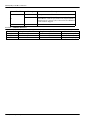
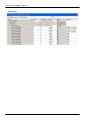
Old Name/Description New Model Name
DeviceMaster UP 2-Port 1E EtherNet/IP DeviceMaster EIP-2202
DeviceMaster UP 2-Port DB9 1E EtherNet/IP DeviceMaster EIP-2102
DeviceMaster UP 2-Port 2E EtherNet/IP DeviceMaster EIP-2402
DeviceMaster UP 2-Port DB9 2E EtherNet/IP DeviceMaster EIP-2302

10 - Chapter 1. Introduction DeviceMaster EtherNet/IP User Guide: 2000424 Rev. M
Product Overview
1.3. Product Overview
Your particular DeviceMaster model may or may not have the EtherNet/IP firmware loaded (depending on
the model you purchased).
Note: Models that have EtherNet/IP loaded on the DeviceMaster are identified in PortVision DX and the
DeviceMaster is labeled accordingly.
This document describes how to configure the DeviceMaster for the EtherNet/IP protocol after basic
DeviceMaster installation and configuration procedures.
You can configure and manage the DeviceMaster through one of the following methods:
• Embedded web page interface
• EtherNet/IP Interface Profile objects
1.4. EtherNet/IP Firmware
The following subsections provide EtherNet/IP system information.
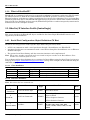
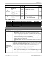
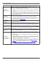
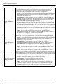
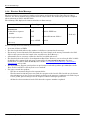
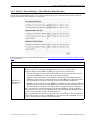
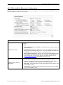
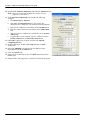
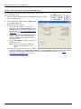
1.4.1. Locating the Latest Software and Documents
You can use the links in this table to check for updated software or documentation.
Software and Documentation FTP
PortVision DX
(Windows)
Use PortVision DX to manage Comtrol Ethernet-attached devices to:
• Scan the network for attached devices
• View networked devices in real-time
• Access product-specific network settings configurations
• Assign IP addresses and network settings to one or multiple
devices
• Upload the latest firmware or Bootloader
• Save and load configuration files
• Access DeviceMaster configuration web pages
• Access Telnet/SSH sessions
• Remotely reboot devices
• Download technical documentation
• Enable event logging to assist in monitoring and troubleshooting
• Create shortcuts to quickly access your favorite applications
• Organize devices into folders and create multiple views
• Enter notes about a folder or device
EtherNet/IP Firmware
This is the application that may or may not have been loaded on the
DeviceMaster depending on the model that was ordered.
You may need to use PortVision DX to load this firmware.

DeviceMaster EtherNet/IP User Guide: 2000424 Rev. M Chapter 1. Introduction - 11
Data Type Definitions
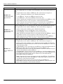
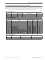
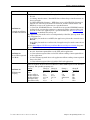
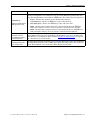
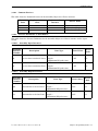
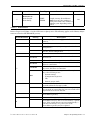
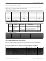
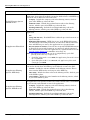
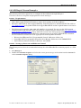
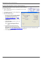
1.4.2. Data Type Definitions
The following list defines the available data types.
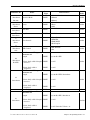
EtherNet/IP Hardware
Installation and Configuration
Guide
This contains hardware installation, configuration information, and
connector information.
This includes using PortVision DX to configure the IP address and if
necessary, how to update the firmware.
EtherNet/IP Interface
Configuration Quick Start
This document with web interface configuration procedures.
EtherNet/IP User Guide
The User Guide contains detailed information about the EtherNet/IP
(application) firmware, which includes additional information about
the web configuration interface for EtherNet/IP.
It also discusses the example PLC programs that were installed on
your system and provides a Programming Interface chapter.
DeviceMaster UP Filtering and
Data Extraction Reference
Guide
This Guide discusses the data extraction and filtering processes in the
DeviceMaster are designed to off load as much work as possible from
the PLC and/or application and provide a very simple and easy to use
interface for standard RFID and barcode data.
This functionality and interface is designed to save dozens, possibly
hundreds of lines of ladder logic in a typical PLC program.
Data Type Definition
USINT Unsigned short integer (8-bits)
UINT Unsigned integer (16-bit)
UDINT Unsigned double integer (32-bits)
INT Signed integer (16-bits)
DINT Signed double integer (32-bits)
BYTE Bit string (8-bits)
WORD Bit string (16-bits)
DWORD Bit string (32-bits)
STRING Character string (1-byte per character)
Software and Documentation FTP

12 - Chapter 1. Introduction DeviceMaster EtherNet/IP User Guide: 2000424 Rev. M
Terms and Definitions
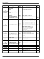
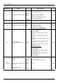
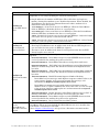
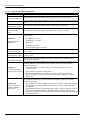
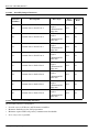
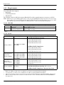
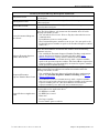
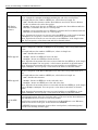
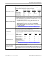
1.4.3. Terms and Definitions
This section uses the following terms and definitions.
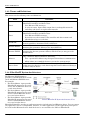
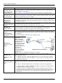
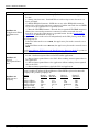
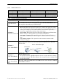
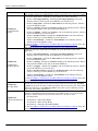
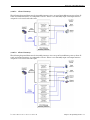
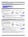
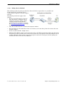
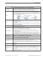
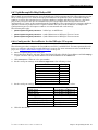
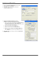
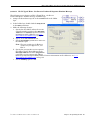
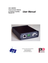
1.4.4. EtherNet/IP System Architecture
The Ethernet TCP/IP firmware
provides a raw/ASCII interface to both
serial and Ethernet TCP/IP devices.
For example:
• The DeviceMaster 1-port provides
EtherNet/IP support for one serial
device and one Ethernet device for
a total of two devices.
• The DeviceMaster 2-port provides
EtherNet/IP support for two serial
devices and two Ethernet devices
for a total of four devices.
• The DeviceMaster 4-port provides
EtherNet/IP support for four serial
devices and four Ethernet devices
for a total of eight devices.
EtherNet/IP firmware provides an application interface for both serial and Ethernet devices. You can connect
any application, such as a configuration, database, or control application, via the application socket port to
the serial and/or Ethernet devices while the device(s) are attached to the PLC via EtherNet/IP.
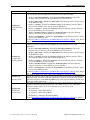
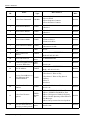
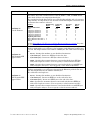
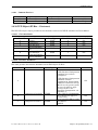
Term Definition
Class 1
Otherwise called implicit messaging, is a method of communication between
EtherNet/IP controllers and devices that:
• Uses Ethernet UDP messages.
• Is cyclic in nature. Input and/or output data is exchanged between the
controllers and devices at regular time intervals.
Class 3
Otherwise called explicit messaging, is a method of communication between
EtherNet/IP controllers and devices that:
• Uses Ethernet TCP/IP messages.
• By itself is not cyclic in nature. The controller and devices must send
individual messages to each other.
EtherNet/IP
An Ethernet based industrial communication protocol utilized to communicate
between controllers, often times PLCS, and devices.
Ethernet TCP/IP
Standard Ethernet communications protocol utilizing socket communication
interfaces that guarantees delivery to the intended device.
Ethernet UDP/IP
Standard Ethernet communications protocol utilizing socket communication
interfaces that does not guarantee delivery. The data may or may get to the
intended device.
Multicast
Multicast addressing involves Ethernet devices sending messages to each other
using a multicast address. Multicast addressing:
• Uses a specified IP address range designated for multicast communication.
• Allows either one or multiple devices to receive the same messages.
Point-to-Point
Point-to-Point, otherwise called unicast, addressing involves Ethernet devices
sending messages directly to each other using their own IP addresses. Messages
are sent to only one device.
Comtrol EtherNet/IP System Architecture (V3.x)

DeviceMaster EtherNet/IP User Guide: 2000424 Rev. M Chapter 1. Introduction - 13
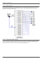
Filtering and Data Extraction Functionality (Patent Pending)
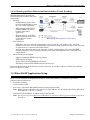
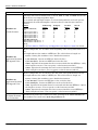
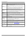
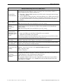
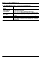
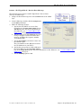
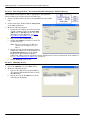
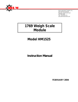
1.4.5. Filtering and Data Extraction Functionality (Patent Pending)
EtherNet/IP firmware provides the
following filtering and data extraction
functionality:
•Filtering
- String Filtering of up to 128
bytes of raw/ASCII data to both
the PLC and/or application.
- RFID filtering of EPCglobal
formatted RFID tag data to
both the PLC and/or
application.
- Barcode filtering of all UPC/
EAN formatted barcodes data
to both the PLC and/or
application.
• Data extraction
- RFID data extraction extracts all parameters, such as company code, product code, and serial
numbers, from any or all of the 43 EPCglobal tag formats. It then transfers the data to the PLC and/
or application in a consistent and simple format.
- Barcode data extraction extracts the company, product, and numbering codes from UPC/EAN
formatted barcodes. It then transfers the data to the PLC and/or application in a consistent and
simple format.
• Environment specific support
- Support for multiple RFID reader tag formats.
- RFID antenna grouping.
- Aging of filtered string/RFID/barcode entries.
- Discarding of unrecognized RFID and barcode messages.
For detailed information about filtering and data extraction, see the DeviceMaster UP Filtering and Data
Extraction Reference Guide.
1.5. EtherNet/IP Application Setup
Before you can configure the EtherNet/IP firmware on the DeviceMaster, you must have previously
performed the following steps:
• Install the hardware
• Install PortVision DX
• If necessary, upload the EtherNet/IP firmware using PortVision DX
Note: Models that have EtherNet/IP loaded on the DeviceMaster are identified in PortVision DX and the
DeviceMaster is labeled accordingly.
• Configure the DeviceMaster IP address using PortVision DX
Note: If necessary, refer to the EtherNet/IP Hardware Installation and Configuration Guide
for the above
procedures.
EtherNet/IP Filtering Functionality (V3.x)

14 - Chapter 1. Introduction DeviceMaster EtherNet/IP User Guide: 2000424 Rev. M
EtherNet/IP Application Setup
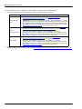
Use the following steps to complete the DeviceMaster configuration for EtherNet/IP.
1. Select the appropriate programming procedure for the following interfaces:
2. Connect your serial device or devices and make sure all Ethernet devices are attached to the same
Ethernet subnet. If necessary, refer to the EtherNet/IP Hardware Installation and Configuration Guide
.
Interfaces Programming Procedure
ControlLogix
PLC
• Program the PLC. See the instructions in ControlLogix PLC
Programming Example Instructions on Page 157.
• (Optional) Access the DeviceMaster Serial | Port and Ethernet | Device
Configuration pages to configure the serial/socket port settings, if you did
not configure the serial/socket port setting in the PLC program. See the
DeviceMaster Interface Configuration Guide for procedures and reference
Embedded Configuration Pages
on Page 89, if necessary.
SLC or
MicroLogix PLC
• Program the SLC or MicroLogix PLC, see the instructions in SLC or
MicroLogix PLC Programming Example Instructions on Page 170.
• Access the DeviceMaster Serial | Port and Ethernet | Device
Configuration pages to configure the serial/socket port settings. See the
DeviceMaster Interface Configuration Guide for procedures and reference
Embedded Configuration Pages
on Page 89, if necessary.
PLC-5 PLC
• Program the PLC-5 PLC, see the instructions in PLC-5 PLC
Programming Example Instructions on Page 197.
• Access the DeviceMaster Serial | Port and Ethernet | Device
Configuration pages to configure the serial/socket port settings. See the
DeviceMaster Interface Configuration Guide for procedures and reference
Embedded Configuration Pages
on Page 89, if necessary.

DeviceMaster EtherNet/IP User Guide: 2000424 Rev. M Chapter 2. Data Transfer - 15
Chapter 2. Data Transfer
This chapter discusses data transfer.
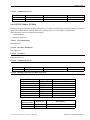
2.1. Data Message Format
The following data message format is used for all interfaces. The ControlLogix interface uses SINT, (8 bit
bytes), and the MicroLogix/SLC/PLC-5 interface uses 16 bit words for the data arrays. All data is sent to and
received from the PLC in little endian format.
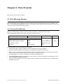
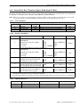
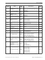
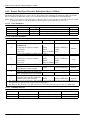
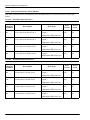
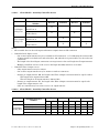
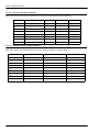
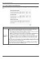
2.1.1. Receive Data Message
The Receive Data message format contains a sequence number, a length and a data array.
The following table displays the format of the Receive Data message.
Receive messages have the following characteristics:
• The Produced data sequence number is incremented when the data is updated.
• The data length field indicates the number of valid bytes contained in the message.
• The message received from the PLC determines the actual length of the message returned to the PLC.
(This is often greater than the length of the actual Receive Data message.)
• All unused bytes in a message returned to the PLC are filled with zeros.
• The GW EIP/ASCII supports serial packets of up 1518 bytes and socket packets up to 2048 bytes in the
Write-To-Tag/File transfer to PLC mode.
• For large received data packets, see sections on Serial and Socket Data Transfer objects or MicroLogix/
SLC/PLC-5 interface.
Name Data Type Data Value(s) Access Rule
Receive (DeviceMaster to PLC) message data
Read-only
Structure of:
Produced data sequence number UINT 0-65535 (FFFF hex)
Data length (in bytes) UINT 0-(MSG payload-4)
Data array Array of SINT 0-255

16 - Chapter 2. Data Transfer DeviceMaster EtherNet/IP User Guide: 2000424 Rev. M
Transmit Data Message
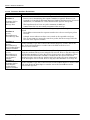
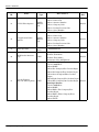
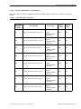
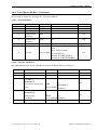
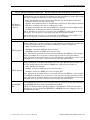
2.1.2. Transmit Data Message
Just like the Receive Data message, the Transmit Data message format contains a sequence number, a length
and a data array.
The following table displays the format of the Transmit Data message.
Transmit messages have the following characteristics:
• For Write MSG from PLC mode, all messages received from a PLC will be transmitted, whether or not the
produced data sequence number has changed or not.
• For Class 1 from PLC mode, messages received from a PLC will only be transmitted if the sequence
number has changed.
•If the TX MSG Sequence Number Checking option is selected, produced data sequence numbers that are not
incremented from the last transmit message will be identified as errors. Statistics will be provided in the
diagnostic web pages.
• The data length field indicates the number of valid bytes contained in the message.
• The actual length of a message received from the PLC may contain extra, unused data.
• It ignores all unused bytes in a message.
•A Get returns the last successfully transmitted serial/socket packet.
Name Data Type Data Value(s) Access Rule
Transmit (PLC to DeviceMaster) message data
Read/Write
Structure of:
Produced data sequence number UINT 0-65535 (FFFF hex)
Data length (in bytes) UINT 0-(MSG payload-4)
Data array Array of SINT 0-255

DeviceMaster EtherNet/IP User Guide: 2000424 Rev. M Chapter 2. Data Transfer - 17
Data Transfer Methods
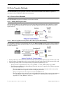
2.2. Data Transfer Methods
The GW EIP/ASCII gateway provides a selection of data transfer methods and a number of options to
customize the data handling for different environments.
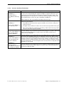
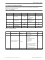
2.2.1. Receive Data Methods
The GW EIP/ASCII supports the following receive data methods:
2.2.1.1. Polling-PLC Requests Data
Also called Slave-Mode for some industrial protocols, the polling method requires the controller to request
received data from the DeviceMaster via messages. The DeviceMaster does not respond until it receives a
request for data.
2.2.1.2. Write-to-Tag/File Gateway Writes Data Directly Into PLC Memory
Also called Master-Mode for some industrial protocols, the Write-to-Tag/File method requires the DeviceMaster
to send messages that write data directly into a tag or file on the PLC. The DeviceMaster sends new data to
the PLC immediately.
• Serial packets up to 1518 bytes may be received while operating in the Write-To-Tag transfer to plc mode.
• Socket packets up to 2048 bytes may be received while operating in the Write-To-Tag transfer to plc mode.
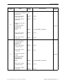
• ControlLogix family PLCs (ControlLogix/CompactLogix/SoftLogix/FlexLogix, etc):
- All tags must be single dimension arrays of type SINT. (i.e. Com1_RdData[444], type= SINT)
- For packets over 440 bytes, the DeviceMaster places the data into a sequence of tags. These tags must
meet the following criteria:
- The entire sequence of tags must be large enough to contain the maximum sized receive packet
plus four SINTS for the sequence number and length parameters.
- All tags except the last of the sequence must be 444 SINTs in size.
- The tags must have the same base name and numbered in sequence. The first tag is not numbered
(i.e. Com1_RxData), the second tag has a 2 appended (i.e. Com1_RxData2), the third has a 3
appended (i.e. Com1_RxData3) and so on.

18 - Chapter 2. Data Transfer DeviceMaster EtherNet/IP User Guide: 2000424 Rev. M
Class 1 Connection (Input Only)-PLC and Gateway Utilize an I/O Connection
- The sequence number and total length is placed in the first tag and the first tag is the last tag
updated. Therefore, once the sequence number is updated, the entire serial packet has been
received and the PLC can process the data.
• For MicroLogix/SCL/PLC-5 PLCs:
- All files must be of type integer, (i.e. N10:0, length = 256)
- For large received data packets:
- The data is automatically placed in sequential files.
- The files must be 256 integers in size with the exception of the last file. The last file may be shorter
than 256 integers as long as the total length of all files in the sequence is sufficient to hold the
largest receive packet, plus two integers for the sequence number and length parameters.
- All data has been transferred to the PLC when the sequence number is updated.
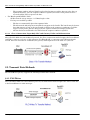
2.2.1.3. Class 1 Connection (Input Only)-PLC and Gateway Utilize an I/O Connection
Also called I/O Mode for some industrial protocols, the Class 1 connection method requires the DeviceMaster
and PLC to connect to each via an I/O connection. For EtherNet/IP, a connection over UDP must first be
created. Once the connection is established, the gateway sends input data to the PLC at a cyclic rate.
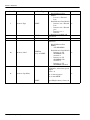
2.3. Transmit Data Methods
The DeviceMaster gateway supports the following transmit data methods.
2.3.1. PLC-Writes
Also called Slave-Mode for some industrial protocols, the PLC-Writes method requires the PLC to send data
to the DeviceMaster via write messages.

DeviceMaster EtherNet/IP User Guide: 2000424 Rev. M Chapter 2. Data Transfer - 19
Class 1 Connection (Input & Output) - PLC and DeviceMaster Utilize an I/O Connection
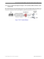
2.3.2. Class 1 Connection (Input & Output) - PLC and DeviceMaster Utilize an I/O
Connection
Also called I/O Mode for some industrial protocols, the Class 1 connection method requires DeviceMaster and
PLC to connect via an I/O connection. For EtherNet/IP, a connection over UDP must first be created. Once the
connection is established, the PLC and DeviceMaster continually exchange data at a cyclic rate.

20 - Chapter 2. Data Transfer DeviceMaster EtherNet/IP User Guide: 2000424 Rev. M
Class 1 Connection (Input & Output) - PLC and DeviceMaster Utilize an I/O Connection
Page is loading ...
Page is loading ...
Page is loading ...
Page is loading ...
Page is loading ...
Page is loading ...
Page is loading ...
Page is loading ...
Page is loading ...
Page is loading ...
Page is loading ...
Page is loading ...
Page is loading ...
Page is loading ...
Page is loading ...
Page is loading ...
Page is loading ...
Page is loading ...
Page is loading ...
Page is loading ...
Page is loading ...
Page is loading ...
Page is loading ...
Page is loading ...
Page is loading ...
Page is loading ...
Page is loading ...
Page is loading ...
Page is loading ...
Page is loading ...
Page is loading ...
Page is loading ...
Page is loading ...
Page is loading ...
Page is loading ...
Page is loading ...
Page is loading ...
Page is loading ...
Page is loading ...
Page is loading ...
Page is loading ...
Page is loading ...
Page is loading ...
Page is loading ...
Page is loading ...
Page is loading ...
Page is loading ...
Page is loading ...
Page is loading ...
Page is loading ...
Page is loading ...
Page is loading ...
Page is loading ...
Page is loading ...
Page is loading ...
Page is loading ...
Page is loading ...
Page is loading ...
Page is loading ...
Page is loading ...
Page is loading ...
Page is loading ...
Page is loading ...
Page is loading ...
Page is loading ...
Page is loading ...
Page is loading ...
Page is loading ...
Page is loading ...
Page is loading ...
Page is loading ...
Page is loading ...
Page is loading ...
Page is loading ...
Page is loading ...
Page is loading ...
Page is loading ...
Page is loading ...
Page is loading ...
Page is loading ...
Page is loading ...
Page is loading ...
Page is loading ...
Page is loading ...
Page is loading ...
Page is loading ...
Page is loading ...
Page is loading ...
Page is loading ...
Page is loading ...
Page is loading ...
Page is loading ...
Page is loading ...
Page is loading ...
Page is loading ...
Page is loading ...
Page is loading ...
Page is loading ...
Page is loading ...
Page is loading ...
Page is loading ...
Page is loading ...
Page is loading ...
Page is loading ...
Page is loading ...
Page is loading ...
Page is loading ...
Page is loading ...
Page is loading ...
Page is loading ...
Page is loading ...
Page is loading ...
Page is loading ...
Page is loading ...
Page is loading ...
Page is loading ...
Page is loading ...
Page is loading ...
Page is loading ...
Page is loading ...
Page is loading ...
Page is loading ...
Page is loading ...
Page is loading ...
Page is loading ...
Page is loading ...
Page is loading ...
Page is loading ...
Page is loading ...
Page is loading ...
Page is loading ...
Page is loading ...
Page is loading ...
Page is loading ...
Page is loading ...
Page is loading ...
Page is loading ...
Page is loading ...
Page is loading ...
Page is loading ...
Page is loading ...
Page is loading ...
Page is loading ...
Page is loading ...
Page is loading ...
Page is loading ...
Page is loading ...
Page is loading ...
Page is loading ...
Page is loading ...
Page is loading ...
Page is loading ...
Page is loading ...
Page is loading ...
Page is loading ...
Page is loading ...
Page is loading ...
Page is loading ...
Page is loading ...
Page is loading ...
Page is loading ...
Page is loading ...
Page is loading ...
Page is loading ...
Page is loading ...
Page is loading ...
Page is loading ...
Page is loading ...
Page is loading ...
Page is loading ...
Page is loading ...
Page is loading ...
Page is loading ...
Page is loading ...
Page is loading ...
Page is loading ...
Page is loading ...
Page is loading ...
Page is loading ...
Page is loading ...
Page is loading ...
Page is loading ...
Page is loading ...
Page is loading ...
Page is loading ...
Page is loading ...
Page is loading ...
Page is loading ...
Page is loading ...
Page is loading ...
Page is loading ...
Page is loading ...
Page is loading ...
Page is loading ...
Page is loading ...
Page is loading ...
Page is loading ...
Page is loading ...
-
 1
1
-
 2
2
-
 3
3
-
 4
4
-
 5
5
-
 6
6
-
 7
7
-
 8
8
-
 9
9
-
 10
10
-
 11
11
-
 12
12
-
 13
13
-
 14
14
-
 15
15
-
 16
16
-
 17
17
-
 18
18
-
 19
19
-
 20
20
-
 21
21
-
 22
22
-
 23
23
-
 24
24
-
 25
25
-
 26
26
-
 27
27
-
 28
28
-
 29
29
-
 30
30
-
 31
31
-
 32
32
-
 33
33
-
 34
34
-
 35
35
-
 36
36
-
 37
37
-
 38
38
-
 39
39
-
 40
40
-
 41
41
-
 42
42
-
 43
43
-
 44
44
-
 45
45
-
 46
46
-
 47
47
-
 48
48
-
 49
49
-
 50
50
-
 51
51
-
 52
52
-
 53
53
-
 54
54
-
 55
55
-
 56
56
-
 57
57
-
 58
58
-
 59
59
-
 60
60
-
 61
61
-
 62
62
-
 63
63
-
 64
64
-
 65
65
-
 66
66
-
 67
67
-
 68
68
-
 69
69
-
 70
70
-
 71
71
-
 72
72
-
 73
73
-
 74
74
-
 75
75
-
 76
76
-
 77
77
-
 78
78
-
 79
79
-
 80
80
-
 81
81
-
 82
82
-
 83
83
-
 84
84
-
 85
85
-
 86
86
-
 87
87
-
 88
88
-
 89
89
-
 90
90
-
 91
91
-
 92
92
-
 93
93
-
 94
94
-
 95
95
-
 96
96
-
 97
97
-
 98
98
-
 99
99
-
 100
100
-
 101
101
-
 102
102
-
 103
103
-
 104
104
-
 105
105
-
 106
106
-
 107
107
-
 108
108
-
 109
109
-
 110
110
-
 111
111
-
 112
112
-
 113
113
-
 114
114
-
 115
115
-
 116
116
-
 117
117
-
 118
118
-
 119
119
-
 120
120
-
 121
121
-
 122
122
-
 123
123
-
 124
124
-
 125
125
-
 126
126
-
 127
127
-
 128
128
-
 129
129
-
 130
130
-
 131
131
-
 132
132
-
 133
133
-
 134
134
-
 135
135
-
 136
136
-
 137
137
-
 138
138
-
 139
139
-
 140
140
-
 141
141
-
 142
142
-
 143
143
-
 144
144
-
 145
145
-
 146
146
-
 147
147
-
 148
148
-
 149
149
-
 150
150
-
 151
151
-
 152
152
-
 153
153
-
 154
154
-
 155
155
-
 156
156
-
 157
157
-
 158
158
-
 159
159
-
 160
160
-
 161
161
-
 162
162
-
 163
163
-
 164
164
-
 165
165
-
 166
166
-
 167
167
-
 168
168
-
 169
169
-
 170
170
-
 171
171
-
 172
172
-
 173
173
-
 174
174
-
 175
175
-
 176
176
-
 177
177
-
 178
178
-
 179
179
-
 180
180
-
 181
181
-
 182
182
-
 183
183
-
 184
184
-
 185
185
-
 186
186
-
 187
187
-
 188
188
-
 189
189
-
 190
190
-
 191
191
-
 192
192
-
 193
193
-
 194
194
-
 195
195
-
 196
196
-
 197
197
-
 198
198
-
 199
199
-
 200
200
-
 201
201
-
 202
202
-
 203
203
-
 204
204
-
 205
205
-
 206
206
-
 207
207
-
 208
208
-
 209
209
-
 210
210
-
 211
211
-
 212
212
-
 213
213
-
 214
214
-
 215
215
-
 216
216
-
 217
217
-
 218
218


Comtrol DeviceMaster UP – EtherNet/IP User guide
- Category
- Software
- Type
- User guide
- This manual is also suitable for
Ask a question and I''ll find the answer in the document
Finding information in a document is now easier with AI
Related papers
-
Comtrol DeviceMaster 500 Installation and Configuration Guide
-
-
-
Comtrol DeviceMaster UP – Modbus TCP User guide
-
-
-
-
-
-
Other documents
-
Alien ALR-9800 User manual
-
red lion 7000 Series Installation and User Manual
-
 ProSoft Technology AN-X-AMX User manual
-
Allen-Bradley SLC 500 Reference guide
-
Datalogic EtherNet/IP DS6 00 Series Installation and User Manual
-
Allen-Bradley 1785 PLC-5 Reference guide
-
 The Helman Group HM1525 User manual
-
Lika XAC81 User manual
-
Mitsubishi Electric MITSUBISHI CNC EtherNet/IP User manual
-
SICK Comtrol DeviceMaster Operating instructions

