Alarm.Com YL6-143IS10 is a wireless indoor/outdoor PIR motion detector with built-in camera. It is designed to work with Alarm.com security systems and provides both motion detection and visual verification of alarms. The device is easy to install and can be placed on a flat surface or mounted on a wall or ceiling. It has a wide-angle lens that provides a 90-degree field of view, and its PIR sensor can detect motion up to 40 feet away. The camera has a resolution of 640x480 and can capture images or videos when motion is detected. These images or videos are then sent to the Alarm.
Alarm.Com YL6-143IS10 is a wireless indoor/outdoor PIR motion detector with built-in camera. It is designed to work with Alarm.com security systems and provides both motion detection and visual verification of alarms. The device is easy to install and can be placed on a flat surface or mounted on a wall or ceiling. It has a wide-angle lens that provides a 90-degree field of view, and its PIR sensor can detect motion up to 40 feet away. The camera has a resolution of 640x480 and can capture images or videos when motion is detected. These images or videos are then sent to the Alarm.


-
 1
1
-
 2
2
-
 3
3
-
 4
4


Alarm.Com YL6-143IS10 User manual
- Type
- User manual
- This manual is also suitable for
Alarm.Com YL6-143IS10 is a wireless indoor/outdoor PIR motion detector with built-in camera. It is designed to work with Alarm.com security systems and provides both motion detection and visual verification of alarms. The device is easy to install and can be placed on a flat surface or mounted on a wall or ceiling. It has a wide-angle lens that provides a 90-degree field of view, and its PIR sensor can detect motion up to 40 feet away. The camera has a resolution of 640x480 and can capture images or videos when motion is detected. These images or videos are then sent to the Alarm.
Ask a question and I''ll find the answer in the document
Finding information in a document is now easier with AI
Related papers
-
Alarm.Com ADC-IS-100-LP Installation guide
-
-
-
-
-
-
Alarm.Com Concord 4 CDM Installation guide
-
-
-
Other documents
-
QOLSYS QZ8103-840 Installation guide
-
Legrand PW1020 User guide
-
DSC PowerSeries Neo 3G8080 Installation guide
-
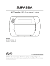 Impassa SCW9055I-433 Installation guide
-
Johnson Controls IQ PANEL User manual
-
QOLSYS QS9207-5208-124 Installation guide
-
-
-
Interlogix Simon XT/XTi GSM Module v4 Installation guide
-
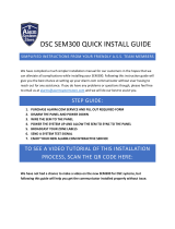 Alarm System Store ADC SEM300 Installation guide

