Page is loading ...

OLGAS-H – High pressure spring return hydraulic actuator
Use and maintenance manual
© Copyright by BIFFI Italia. All right reserved. Pag. 1
Contents may change without notice
MAN 609
Use and maintenance manual
OLGAS-H
SPRING RETURN HIGH
PRESSURE HYDRAULIC
ACTUATOR
5
20/04/18
Updated DATAPLATE
Ermanni
Orefici
Vigliano
4
18/04/16
Updated applicable
regulation (chapter 1.1.1)
Ermanni
Orefici
Vigliano
3
07/08/13
Added lifting procedure for
valve with horizontal axis
Ermanni
Stoto
Vigliano
2
31/07/12
General update
Ermanni
Stoto
Vigliano
1
08/02/10
General update
Ermanni
Stoto
Vigliano
0
05/05/99
Document release
Lazzarini
Aliani
Ziveri
Rev.
Date
Description
Prepared
Checked
Approved

OLGAS-H – High pressure spring return hydraulic actuator
Use and maintenance manual
© Copyright by BIFFI Italia. All right reserved. Pag. 2
Contents may change without notice
TABLE OF CONTENTS
1 General warnings ................................................................ 4
1.1 GENERALITIES .......................................................................... 4
1.1.1 Applicable regulation ............................................................... 4
1.1.2 Terms and conditions .............................................................. 4
1.2 IDENTIFICATION PLATE ........................................................... 5
1.3 INTRODUCING THE ACTUATOR .............................................. 5
1.4 DATA SHEET .............................................................................. 6
2 Installation ........................................................................... 6
2.1 CHECKS UPON ACTUATOR RECEIPT ..................................... 6
2.2 STORAGE ................................................................................... 7
2.3 ACTUATOR ASSEMBLY ON THE VALVE ................................. 7
2.3.1 Types of assembly .................................................................. 7
2.3.2 ACTUATOR HANDLING (VALVE STEM WITH VERTICAL
AXIS) ..................................................................................... 12
2.3.3 VALVE STEM WITH HORIZONTAL AXIS ............................ 16
2.4 hydraulic CONNECTIONS ........................................................ 18
2.5 ELECTRICAL CONNECTIONS (IF ANY) .................................. 19
2.6 COMMISSIONING .................................................................... 19
3 Operation and use ............................................................. 20
3.1 OPERATION DESCRIPTION .................................................... 20
3.2 RESIDUAL RISKS ..................................................................... 21
3.3 OPERATIONS ........................................................................... 21
( refer to specific document: operating diagram furnished ) ............. 21
3.3.1 Emergency manual operation ............................................... 21
3.3.2 Remote control operations .................................................... 23
3.4 CALIBRATION OF THE ANGULAR STROKE .......................... 25
3.5 CALIBRATION OF MICROSWITCHES (biffi limit switch box) ... 29
3.6 CALIBRATION OF THE OPERATION TIME (if required) .......... 31
4 Operational tests and inspections ...................................... 32
5 Maintenance ...................................................................... 33
5.1 PERIODIC MAINTENANCE ...................................................... 33
5.1.1 Check and restore oil level in the hydraulic control unit ( refer
to chapt. 7.2 table 5 ) ............................................................ 34
5.2 EXTRAORDINARY MAINTENANCE ........................................ 36
5.3 LUBRICATION OF MECHANISM 41
5.4 DISMANTLING AND DEMOLITION ........................................... 42
6 Troubleshooting ................................................................ 43
6.1 FAILURE OR BREAKDOWN RESEARCH ............................... 43
7 Layouts .............................................................................. 44
7.1 SPARE PARTS ORDER ........................................................... 44
7.2 PARTS-LIST FOR MAINTENANCE AND REPLACING
PROCEDURE .................................................................................. 45
8 Date report for maintenance operations ............................ 52

OLGAS-H – High pressure spring return hydraulic actuator
Use and maintenance manual
© Copyright by BIFFI Italia. All right reserved. Pag. 3
Contents may change without notice
NOTE:
BIFFI Italia S.r.l pays the highest attention to collecting and verifying the
documentation contained in this user manual. However BIFFI Italia S.r.l. is not
liable for any mistakes contained in this manual, for damage or accidents due to
the use of the latter. The information contained is of exclusive reserved ownership
of BIFFI Italia S.r.l and may be modified without prior notice. All rights reserved.

OLGAS-H – High pressure spring return hydraulic actuator
Use and maintenance manual
© Copyright by BIFFI Italia. All right reserved. Pag. 4
Contents may change without notice
1 General warnings
The manual is an integral part of the machine, it should
be carefully read before carrying out any operation and
it should be kept for future references.
1.1 GENERALITIES
BIFFI Italia S.r.l actuators are conceived, manufactured and
controlled according to the Quality Control System in compliance with
EN-ISO 9001 international regulation.
1.1.1 Applicable regulation
EN ISO 12100:2010: Safety of machinery – General principles for
design – Risk assessment and risk reduction
2006/42/EC: Machine directive.
2014/68/EU: Directive for pressure PED equipment
2014/35/EU: Directive for low voltage equipment
2014/30/EU: Directive for the electromagnetic compatibility
2014/34/EU: Directive and safety instructions for use in
hazardous area
1.1.2 Terms and conditions
Biffi Italia srl guarantees that all the items produced are free of
defects in workmanship and manufacturing materials and meet
relevant current specifications, provided they are installed, used and
serviced according to the instructions contained in the present
manual. The warranty can last either one year from the date of
installation by the initial user of the product, or eighteen months from
the date of shipment to the initial user, depending on which event
occurs first. All detailed warranty conditions are specified in the
documentation forwarded together with the product. This warranty
does not cover special products or components not warranted by
subcontractors, or materials that were used or installed improperly or
were modified or repaired by unauthorized staff. In the event that a
fault condition be caused by improper installation, maintenance or
use, or by irregular working conditions, the repairs will be charged
according to applicable fees. The warranty and Biffi Italia srl
liability shall lapse in the event that any modification or
tampering whatsoever be performed on the actuator.

OLGAS-H – High pressure spring return hydraulic actuator
Use and maintenance manual
© Copyright by BIFFI Italia. All right reserved. Pag. 5
Contents may change without notice
1.2 IDENTIFICATION PLATE
It is forbidden to modify the information and the marks without
previous written authorization by BIFFI Italia S.r.l.
The plate fastened on the actuator contains the following information
(Figure1).
Figure 1 – Data plate
1.3 INTRODUCING THE ACTUATOR
The hydraulic actuator OLGAS-H was engineered and is
manufactured to provide fail safe operation for any quarter turn
application such as ball, plug, butterfly valves or dampers, in both
On-Off and Modulating heavy duty service.
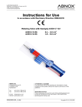
The actuator (see figure 2) is made up of a weatherproof scotch yoke
mechanism transforming the linear movement of the hydraulic
cylinder (on closing or opening) into the rotary movement, which is
necessary for operation. The spring module incorporates up to four
springs, fully encapsulated in a factory-welded cartridge: this ensure
safety to personnel and simplifies assembly. The spring action can
be easily changed in the field from “to close” in “to open” or vice-
versa. The angular stroke of the yoke is adjustable between 82° and
98° by means of the external mechanical stops screwed into the
spring cartridge and into the end flange of the hydraulic cylinder. The
cover of the scotch yoke mechanism is arranged for the assembly of
the required accessories (positioner, signalling limit switches,
position transducer, etc.) by means of proper matching units. The
above mentioned accessories are operated by the actuator drive
sleeve. The housing of the scotch yoke mechanism has a flange with
threaded holes to fix the actuator to the valve either directly or, if
required, with the interposition of an adaptor flange or a mounting
bracket. The actuator yoke has a hole with keyways suitable for the

OLGAS-H – High pressure spring return hydraulic actuator
Use and maintenance manual
© Copyright by BIFFI Italia. All right reserved. Pag. 6
Contents may change without notice
assembly of an insert bush the internal hole of which is machined (by
BIFFI or at Customer's care), according to the shape and dimensions
of the valve stem. BIFFI can supply different types of control system
following Customer's requirements.
The expected lifetime of actuator is approximately 25 years .
Figure 2 – Identification of actuator parts
1.4 DATA SHEET
2 Installation
2.1 CHECKS UPON ACTUATOR RECEIPT
❑ Check that the model, the serial number of the actuator and the
technical data reported on the identification plate correspond with
those of order confirmation (Sect. 1.2).
❑ Check that the actuator is equipped with the fittings as provided for
by order confirmation.
❑ Check that the actuator was not damaged during transportation: if
necessary renovate the painting according to the specification
reported on the order confirmation.
❑ If the actuator is received already assembled with the valve, its
Supply fluid
Hydraulic oil, special versions for fire-
resistant fluids
Operating temperature
Standard: from –30°C to +100°C
Optional: from –60° to +140°C
Supply pressure
Please refer to technical document:
“actuator data-sheet”
Spring cartridge
Hydraulic cylinder
Scotch-yoke
mechanism
Valve coupling
Valve position indicator

OLGAS-H – High pressure spring return hydraulic actuator
Use and maintenance manual
© Copyright by BIFFI Italia. All right reserved. Pag. 7
Contents may change without notice
settings have already been made at the factory.
If the actuator is delivered separately from the valve, it is
necessary to check, and, if required, to adjust, the settings of the
mechanical stops (Sect. 3.4) and of micro-switches (if any) (Sect.
3.5).
2.2 STORAGE
(for handling and lifting procedure, please refer to following
paragraphs : 2.3.2 and 2.3.3)
If the actuator needs storage before installation, follow these steps:
❑ Place it on a wood surface in order not to deteriorate the area of
valve coupling.
❑ Make sure that plastic plugs are present on the pneumatic and
electrical connections (if present).
❑ Check that the cover of the control group and of the limit switch box
(if any) are properly closed.
If the storage is long-term or outdoor:
❑ Keep the actuator protected from direct weather conditions.
❑ Replace plastic plugs of pneumatic and electrical connections (if
any) with metal plugs that guarantee perfect tightness.
❑ Coat with oil, grease or protection disc, the valve coupling area.
❑ Periodically operate the actuator (Sect. 3.3).
2.3 ACTUATOR ASSEMBLY ON THE VALVE
2.3.1 Types of assembly
For coupling to the valve, the housing is provided with a flange with
threaded holes according to Biffi standard tables (SCN6200
SCN6201). The number, dimensions and diameter of the holes are
made in accordance with ISO 5211, but for actuator models 0.3 to 6
the holes are drilled on the centreline in order to allow an easier
assembly of an intermediate flange, when required. This intermediate
flange ( or spool-piece ) can be supplied when the valve flange can
not directly match the actuator flange in its “standard” configuration.
For the biggest actuator models, the actuator flange can be
machined in accordance with the valve flange dimensions.
The yoke has bored with keyways for coupling to the valve stem, the
dimensions of which are according to Biffi standard tables SCN6200
and SCN6201.

OLGAS-H – High pressure spring return hydraulic actuator
Use and maintenance manual
© Copyright by BIFFI Italia. All right reserved. Pag. 8
Contents may change without notice

OLGAS-H – High pressure spring return hydraulic actuator
Use and maintenance manual
© Copyright by BIFFI Italia. All right reserved. Pag. 9
Contents may change without notice

OLGAS-H – High pressure spring return hydraulic actuator
Use and maintenance manual
© Copyright by BIFFI Italia. All right reserved. Pag. 10
Contents may change without notice
If required, for the standard models size 0.3 to 6, Biffi can supply an
insert bush with un-machined bore in accordance with Biffi standard
table SCN6202 enclosed ( see following pages ). On request the
insert bush bore can be machined by Biffi to couple the valve stem,.
The particular execution of the flange and bushing allow the actuator
to be rotated by 90° in 4 different positions according to the following
figure:

OLGAS-H – High pressure spring return hydraulic actuator
Use and maintenance manual
© Copyright by BIFFI Italia. All right reserved. Pag. 11
Contents may change without notice
Position 2 Position 3 Position 4
Rotate insert-bush
180° around vertical-
standard position (1)
Rotate insert-bush 180°
around axis A-A, from
position 2
Rotate insert-bush
180° around axis A-A
from position 1
Insert bush turned upside down
Figure 3 – Insert bush + intermediate coupling flange
The Biffi insert bush with 2 external keys at 45° allows to position the
keyway for the valve every 90°. Consequently actuator can be
mounted in 4 positions at 90° on top of the valve. For biggest
actuator models, the bore of the yoke can be machined according to
the dimensions of valve stem.

OLGAS-H – High pressure spring return hydraulic actuator
Use and maintenance manual
© Copyright by BIFFI Italia. All right reserved. Pag. 12
Contents may change without notice
2.3.2 ACTUATOR HANDLING (VALVE STEM WITH VERTICAL
AXIS)
The lifting and handling of the actuator must be done by
qualified personnel and in accordance with the laws and
regulations in force. Avoid the lifted actuator to be hung
above the personnel.
The actuator must be lifted by means of a suitable lifting
apparatus. The weight of the actuators is indicated in
the technical documentation attached to the equipment
itself.
For lifting and moving the actuator, use only hooks
fitted with safety latch, like the one, for example, shown
in follow figure 2.1
Picture 2.2 – Lifting points for OLGAS-H actuators
1-2 = Lifting points ( obligatory ) 3 = Balancing point
Figure 2.1 Example of hook with
safety latch

OLGAS-H – High pressure spring return hydraulic actuator
Use and maintenance manual
© Copyright by BIFFI Italia. All right reserved. Pag. 13
Contents may change without notice
1 = point of support - 2 = supports for lateral positioning
3 = don’t lay the actuator on tie-rods of cylinder /s and
don’t lay the actuator on accessories ( manual override, pneumatic
control group etc. )
• For lifting unbalanced loads, use ropes of different lengths
or chains with adjustable length.
• Check each time the conditions of all lifting equipment used
and discard it if not in perfect working order.
• Do not knot or twist the ropes so as not to reduce the lifting
capacity or produce torsional effects on the load being lifted.
• Use the utmost caution and remain at a safe distance from
lifted actuator unless absolutely necessary; do not stand or
pass under suspended loads.
• Pay attention in putting under tension the ropes to prevent
the load shifting sideways in an uncontrolled manner.
• Use slings of such length that the angles of the leg from
vertical are as narrow as possible (MAX < 20°).
• During handling, do not transport the suspended actuator
above staff members in charge of the operation.
DO NOT USE the lifting eyelets on actuator to lift valve +
actuator assembly

OLGAS-H – High pressure spring return hydraulic actuator
Use and maintenance manual
© Copyright by BIFFI Italia. All right reserved. Pag. 14
Contents may change without notice
For the transport of OLGAS-H with hydraulic manual hand-pump, when
it was necessary put in horizontal position the tank of MHP, to avoid
leakage on oil level stick, substitute these with a blind-plug during the
transport (a specific warning label for transport in horizontal position is
attached on the MHP body); remove the blind plug and restore the
dipstick before operate the actuator with MHP.
BIFFI hydraulic manual hand-pump must be maintained with tank under
the hand-pump to operate the actuator with MHP properly
OMFB manual hand-pump should be transported and used with MHP
tank in horizontal position, but in position 3 of follow picture (extracted
from OMFB technical documentation) it’ necessary change the position
of suction pipe and breather cap :

OLGAS-H – High pressure spring return hydraulic actuator
Use and maintenance manual
© Copyright by BIFFI Italia. All right reserved. Pag. 15
Contents may change without notice
Failure to comply with the following procedures may impair
product warranty. Installation, commissioning and maintenance
and repair works should be carried out by qualified staff.
A non-conforming assembly could be the source of serious
accidents.
For actuator assembly on the valve:
Check that the assembly position, as shown on the
documentation, complies with system’s geometry. Check the
consistency of the parts of actuator-valve coupling.
❑ Operate the actuator so that it reaches the position matching valve
position (Section 3.3).
❑ Lubricate valve stem with oil or grease.
❑ Properly clean and remove grease from coupling flange surfaces.
❑ Connect, if supplied separately, the adjustment insert to valve stem
and fasten it with the special fastening pins.
❑ Lift the actuator using the special lifting points (Sect. 2.2).
❑ Install the actuator so that valve stem inserts in the coupling area.
This coupling should be made without forcing.
❑ Fasten the two parts with the threaded connections (screws, tie
rods, nuts). If holes of coupling flanges are not aligned, adequately
operate the actuator if necessary move the mechanical stops
backwards (Sect. 3.4).
❑ Fasten threaded connections. Please refer to Table 1.
Table 1: nuts tightening torque
Threading
Tightening
torque (Nm)
M8
20
M10
40
M12
70
M14
110
M16
160
M20
320
M22
420
M24
550
M27
800
M30
1100
M33
1400
M36
1700

OLGAS-H – High pressure spring return hydraulic actuator
Use and maintenance manual
© Copyright by BIFFI Italia. All right reserved. Pag. 16
Contents may change without notice
The screwing values in Table 1 were calculated considering the
materials ASTM A320 L7 for screws or tie rods and ASTM A194
gr.2H for the nuts.
2.3.3 VALVE STEM WITH HORIZONTAL AXIS
The actuator can also be lifted to assemble directly onto the valve
with stem with horizontal axis. To make a correct lifting procedure
proceed as follow:
1) Connect properly the actuator lifting points 1 with chains, and
connect by suitable slings the support brackets 2 and 3

OLGAS-H – High pressure spring return hydraulic actuator
Use and maintenance manual
© Copyright by BIFFI Italia. All right reserved. Pag. 17
Contents may change without notice
2) Balance the weight and lift the actuator until to make possible the
rotation of actuator in its final mounting position, with cylinder on
top, or spring container placed on top, as showed in the following
images:

OLGAS-H – High pressure spring return hydraulic actuator
Use and maintenance manual
© Copyright by BIFFI Italia. All right reserved. Pag. 18
Contents may change without notice
3) Clean the actuator flange and remove anything that might
prevent a perfect adherence to the valve flange and especially all
traces of grease.
4) Lift the actuator near to the valve in such a way that the insert
bush, assembled on the valve stem, enters the actuator drive
sleeve without forcing the coupling . When the insert bush has
entered the actuator drive sleeve, check the holes of the valve
flange. If they do not meet with the holes of the actuator flange or
the stud bolts screwed into them, the actuator drive sleeve must
be rotated; feed the actuator cylinder with air at proper pressure,
indicated on data-sheet for actuator.
5) Tighten the nuts of the connecting stud bolts evenly with the
torque prescribed in the table. The stud bolts must be made of
ASTM A320 L7 steel; the nuts must be made of ASTM A194
grade 2 steel.
6) If possible, operate the actuator to check that it moves the valve
smoothly.
2.4 HYDRAULIC CONNECTIONS
Check that the values of hydraulic supply available are
compatible with those reported on the identification plate of the
actuator.
The connections should be made by qualified staff.
Use pipes, fittings and connections appropriate as for type,
material and dimensions.
Connect the actuator to the hydraulic feed line with fittings and pipes
in accordance to the plant specifications. They must be sized
correctly in order to guarantee the necessary oil flow for the
operation of the actuator, with pressure drops not exceeding the
maximum allowable value. The shape of the connecting piping must
not cause excessive stress to the inlets of the actuator. The piping
must be suitably fastened so as not to cause excessive stress or
loosening of threaded connections, if the system undergoes strong
vibrations. Every precaution must be taken to ensure that any solid or
liquid contaminants, which may be present in the hydraulic pipe-work
to the actuator, are removed to avoid possible damages to the unit or
loss of performance. The inside of the pipes used for the connections
must be well-cleaned before use: wash them with suitable
substances and blow through them with oil or nitrogen. The ends of
the tubes must be well debarred and cleaned. Once the connections
are completed, operate the actuator and check that it functions
correctly, that the operation times meet the plant requirements and
that there are no leakages in the hydraulic connections.

OLGAS-H – High pressure spring return hydraulic actuator
Use and maintenance manual
© Copyright by BIFFI Italia. All right reserved. Pag. 19
Contents may change without notice
2.5 ELECTRICAL CONNECTIONS (IF ANY)
Use components appropriate as for type, material and
dimensions. The connections should be made by qualified
staff. Before carrying out any operation, cut line power off
Safety provisions :
2006/95/EC: Directive for low voltage equipment (until 19
April 2016) 2014/35/EU from 20 April 2016
2004/108/EC: Directive for the electromagnetic
compatibility (until19 April 2016) 2014/30/EU from 20 April
2016
94/9/CE: Directive and safety instructions for use in
hazardous Area(until 19 April 2016) 2014/34/EU from 20
April 2016
Remove plastic plugs from cables entries
❑ Screw firmly the cable glands.
❑ Introduce connection cables.
❑ Make the connections in compliance with applicable wiring diagrams
on the documentation supplied.
❑ Screw the cable gland.
❑ Replace the plastic plugs of unused entries with metal plugs.
2.6 COMMISSIONING
Installation, commissioning and maintenance and repair
works should be made by qualified staff.
Any calibration relative to functional aspects of the
actuator are preset at the factory.
Before any modifications please contact BIFFI Italia S.r.l.
Upon actuator commissioning please carry out the following checks:
❑ Check that the values of hydraulic supply available in the system are
compatible with those reported on the identification plate of the
actuator (Figure 2) and on the documentation supplied.
❑ Check the power voltage of electrical components complies with the
one reported on the documentation supplied.
❑ Check the absence of leakages in the cylinder and in hydraulic
connections.
❑ Check that paint is intact and in case renovate it according to the
specification on order confirmation.
❑ Carry out all kinds of operations and check their proper execution
(Sect. 3.3).
❑ Make a complete functional test in order to verify all the operations
are executed according to operating schematic diagram supplied.

OLGAS-H – High pressure spring return hydraulic actuator
Use and maintenance manual
© Copyright by BIFFI Italia. All right reserved. Pag. 20
Contents may change without notice
3 Operation and use
3.1 OPERATION DESCRIPTION
The actuator is operated by:
1) Pressurized motor fluid.
2) Elastic return of compression helicoidally spring.
In the first case the alimentation fluid pressurizes a chamber of the
cylinder and compresses the spring (Figure 4); this determines the
linear motion of the piston and the consequent rotation motion of the
scotch yoke mechanism to which valve stem is coupled. The fluid
contained in the other chamber is discharged through the return line.
In the second case, cutting off or in case of lack of pressure to the
cylinder and to the pilot of the fast discharge valve, the opening of
the latter is determined, the fast discharge of motor fluid, the quick
extension of the spring and the consequent fast operation of the
actuator. The motor fluid going out from one chamber of the cylinder
partially returns in the other chamber and partially flows through the
discharge line.
For local or remote operations, please refer to technical
documentation furnished with actuators.
For all the relevant information please refer to the specific
documentation supplied.
/