Page is loading ...

www.arrowsheds.com
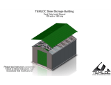
01J
NOTE: These instructions are to be used to add an Extension Module to an
existing Arrow Commander™ or Mountaineer™ Shed. If you are assembling
your shed for the fi rst time, use the manual included in the main carton (C1GA).
Two to three people required for assembly.
Follow all safety precautions in the Commander™/Mountaineer™ Series
Assembly Manual.
Gloves must be worn
at all times to reduce
risk of injury!
TM
R
Note: It may be helpful to refer to the primary Commander™/Mountaineer™ Series Manual you
used when you fi rst assembled your building. If you have misplaced your original Commander™/
Mountaineer™ Series Assembly Manual, it is available online at www.arrowsheds.com. You may
also request an additional copy from customer service: 1-800-851-1085.
COMMANDER
™
SERIES
717750313
MOUNTAINEER
™
SERIES
(Extension Module Addendum)

2
BEFORE YOU BEGIN...
Safety precautions MUST be followed at all times throughout the construction of your building!
•Care must be taken when handling various pieces of your building since
many contain sharp edges. Please wear work gloves, eye protection and long
sleeves when assembling or performing any maintenance on your building.
•Practice caution with the tools being used in the assembly of this extension
module. Be especially familiar with the operation of all power tools.
•Keep children and pets away from the worksite during construction. Do not
allow children to help with assembly.
•Do NOT attempt to assemble this extension module on a windy day. The large
panels can catch the wind like a “sail”, causing them to be whipped around
making construction diffi cult and unsafe.
•At least two people should work together to assemble this extension module.
This will make assembly faster and easier.
•This extension needs to be anchored after assembly. You should anchor
this extension securely in the same manner as your existing Commander™/
Mountaineer™ Shed.
•NEVER concentrate your weight on the roof of the building. When using a
step ladder make sure that it is fully open and on even ground before climbing
on it.
02J
Below is a list of things you will need to install the extension module.
• Work Gloves
• Safety Glasses
• Step Ladder
• No. 2 Phillips Screwdriver (Magnetic Tip Preferred)
• Utility Knife or Scissors
• Pliers
• Carpenter’s Level
• Tape Measure
• Power Drill (Cordless, Variable Speed)
• Nut Driver or Wrench
• Square
• String (for squaring the frame)
• Awl (to align holes)
WHAT YOU NEED
RECOMMENDED TIME SAVERS

3
03J
# PART NO. PART DESCRIPTION QTY.
1 65004 SMALL SCREW (#8AB X 5/16) (8 mm) 180
2 66611 LARGE SCREW (#10AB X 1/2) (13 mm) 40
3 65923 BOLT (#8-32 X 3/8) (10 mm) 92
4 65103 HEX NUT (#8-32) 92
5 66646 WASHER SHEET 7
6 7822 WALL PANEL 4
7 7743 ROOF PANEL 4
8 6015 MID ROOF TRIM 2
9 10680 MID RIDGE CAP 1
10 10625 SIDE WALL ANGLE 2
11 10632 SIDE FRAME 2
12 10634 MID SIDE WALL CHANNEL 2
13 10650 MID ROOF BEAM 4
14 10641 TRUSS POST 2
15 10642 TRUSS POST INSERT 2
16 10643 UPPER CHORD TRUSS 2
17 10644 LOWER CHORD TRUSS 2
18 10645 TRUSS SPLICE 1
19 10646 TRUSS KNEE BRACE 4
20 7003-7004 SHEAR PLATE (LEFT / RIGHT) 8
66
66
7
7
78
8
9
10
10
11
11
12
12
13 13
13
14
15
16
17
18
19
20
Check that the following items are included in this carton:
Reading and following all steps carefully will help make assembly quicker and easier. Before
you begin assembly, be sure to confi rm that all the parts for your building are present using
the checklist on this page. If parts are missing, include the model number of your building and
contact customer service.
Customer Service:
1-800-851-1085 or
4
11/32 Hex.
3
#2 Phillips
2
#2 Phillips
1
#2 Phillips
5
19
16
14
15

4
57 1/2”
57 1/2”
04J
Step 1 - Extend the existing base to accommodate the new length of your building.
Extend the base by 57 1/2” (146,1 cm) for each
Extension Module you have purchased.
Use similar materials and construction to
match the existing base, in accordance with
any local regulations.
PRESSURE TREATED LUMBER MUST NOT
COME IN CONTACT WITH YOUR BUILDING.
Step 2 - Assemble the Trusses (assemble one Truss for each Extension Module purchased).
Align the bottoms of the Truss Post and
Truss Post Insert and join as shown.
Insert Large Screws along both sides of
the Truss Post where holes align.
Build two Assemblies.
ASSEMBLY NOTE: Each Extension Module
contains one additional Truss Section. The
Truss Section contained in this Extension
Module is identical to the Truss Sections already
installed in your building. If in doubt about a step
or procedure, it may be helpful to see how the
existing Truss Sections are installed in your
building.
You will need the following parts for this step:
10641 Truss Post
10642 Truss Post Insert
10643 Upper Chord Truss
10644 Lower Chord Truss
10645 Truss Splice
10646 Knee Brace
7003 Shear Plate LT
7004 Shear Plate RT
Nut
11/32 Hex.
Bolt
#2 Phillips
Small Screw
#2 Phillips
Large Screw
#2 Phillips
The following fasteners are used throughout
assembly. Be sure to use the proper fastener
where indicated.
Do not reuse fasteners. Use new fasteners in-
cluded in this Module when reinstalling parts.
Leave top holes open.
10641
10642
10641
10642
10641
10642
146,1 cm
146,1 cm

5
05J
Next, insert the Upper/Lower Chord Truss Assembly into the
Truss Post Assembly as shown. Secure with Bolts and Nuts. Do
not tighten at this time.
Attach Knee Braces to Truss using
Large Screws as shown. Do not
tighten at this time. With the Truss
assembled, check that the width of
the Truss is 118 1/4” (300,4 cm) across
the top and bottom of the Truss. If so,
tighten all fasteners. Repeat steps to
build additional Trusses.
With the Upper and Lower Chord Trusses
positioned as shown below, attach Shear
Plates where indicated below.
Attach Shear Plates using Bolts and
Nuts to Upper Chord fi rst, then to the
Lower Chord.
Build two Assemblies.
Repeat for additional Trusses
10641
10642
10643
10644
10645
10646
10646
118 1/4”
300,4 cm
CORRECT
INCORRECT
Holes must align in this direction.
Not this direction
10643
10644
10643
10644
Build two Assemblies.
10643
10644
7003
7003
7004
7004
Attach Truss Splice to Truss using Bolts and Nuts as shown below,
but do not tighten at this time. Temporarily secure the peak of the
Truss using two Bolts and Nuts as shown.

6
06J
Partially disassemble the rear of the building:
A) Remove the rear Roof Trim from both sides of building.
B) Remove four Bolts from rear Ridge Cap.
C) Remove the last Wall Panel and last full-size Roof Panel at
the rear of the building.
D) Remove the rear Ridge Cap.
Step 3 - Partially disassemble the rear of the building.
A
B
C
D

7
07J
IMPORTANT: When removing the Wall Panels over a Truss, you will need
to ‘roll’ the Panels as shown to be able to remove the Bolt attaching the Panels
at the overlap. You will need to remove some Screws from the adjacent Panel
to be able to roll the Panel back.
REMOVE SCREWS FROM NEXT PANEL
TO ACCESS NUT BEHIND RIB.
B
You may also need to remove some Screws or Bolts in adjacent
Panels in order to remove the Panels shown.
Place these parts in a safe place until they are needed later.
A C
Remove Screw at bottom of End Roof
Panels before continuing.
Remove four Bolts at end of Ridge Cap.
Remove Roof Trim.
D
Remove last two Bolts.

8
08J
Next, the Rear Wall will be removed as a unit as shown using the following procedure:
A) Unfasten the rear Roof Beams from the main building.
B) Unfasten the Side Wall Angle where it connects to the Rear Wall.
C) Unfasten the rear Wall Channels from the last Truss.
D) Unfasten the Rear Wall from the Floor Frame.
Carefully remove the Rear Wall and set in a safe place until it is needed later.
IMPORTANT: TWO PEOPLE SHOULD BE SUPPORTING THE REAR WALL AS IT IS UNFASTENED !
A B
D
C
B
D
C
A
Step 4 - Remove the Rear Wall.

9
09J
Step 5 - Install all new Truss Sections.
A) Attach the Side Frame that came with the Module to the rear of the building as shown with two
Bolts and Nuts. Side Frames should overlap by 8 1/4 ” (21,0 cm). Attach the Truss Assembly to
the Floor Frame 57 1/2 ” (146,1 cm) behind the previous Truss using a Large Screw.
You will need the following parts for this step:
10625 Side Wall Angle
10632 Side Frame
10634 Side Wall Channel
10650 Roof Beam
All Truss Assemblies
Existing Floor Frame
A
A
Step 5 continues on next page.
57 1/2 ”
(146,1 cm)
8 1/4”
21,0 cm
Overlap Length

10
10J
B) Install Roof Beams with Bolts and Nuts.
C) Install Side Wall Channel with Large Screws.
D) Install Side Wall Angles. Wall Angles should overlap by 8 1/4 ” (21,0 cm). Use Bolts and
Nuts where Wall Angles overlap. Use Large Screws where Wall Angles meet Trusses.
E) Repeat for additional Modules.
Each Module is installed identically to the existing Truss Sections:
8 1/4”
21,0 cm
Overlap Length
B
D EC
Overlap Wall Angles by 8 1/4 ”
(21,0 cm)
B
C
D
Step 5 - Continued.
10650
10650
10650 10650
10634 10625
10625

11
11J
Step 6 - Reinstall the Rear Wall.
Once all Truss Sections have been erected, you may reinstall the Rear Wall as follows:
A) Fasten the Rear Wall to the Floor Frame with Large Screws.
B) Fasten the rear Wall Channels from the last Truss with Large Screws.
C) Fasten the Side Wall Angle to the Rear Wall with Large Screws. If holes do not align, it may be
helpful to fasten the Side Wall Angle to the Rear Wall fi rst, and then to the rest of the building.
D) Fasten the rear Roof Beams to the main building with Bolts and Nuts.
AB
CD
A
B
C
D

12
Crimped Rib
Uncrimped Rib
Whenever a crimped rib and an uncrimped rib
meet, the crimped rib should be placed UNDER
the uncrimped rib if possible. See next page.
Use the diagram to the right when attaching Wall Panels.
• Secure the top row to Top Frames
• Secure the middle row to Wall Channels
• Secure the lower row to Floor Frames
• Secure the circled holes to the Panel next to it
FASTEN TO TOP FRAMES
FASTEN TO FLOOR FRAMES
FASTEN TO WALL CHANNELS
7822
IMPORTANT: When installing the Wall
Panels over a Truss, you will need to ‘roll’
the Panels as shown to be able to attach the
next Panel at the overlap. When securing the
Panel to the building with Small Screws, do
not insert Screws in the row of holes closest
to the last rib of the Panel. Next, roll the Panel
back slightly and attach the next Panel at the
overlap with a Bolt and Nut in the center hole.
Once this is done, continue securing the Panel
to the building.
LEAVE LAST ROW OF HOLES EMPTY
UNTIL NEXT PANEL IS IN PLACE
Step 7 - Install all Wall Panels.
12J

13
13J
Install ALL Wall Panels:
A) Working one side at a time, lift the Panels into place and secure with three Small Screws in the top
of the Panel, three Small Screws in the middle of the Panel, and three Small Screws in the bottom
of the Panel. Roll the Panel back as shown on the previous page and overlap the rib with the rib of
the next Panel.
B) Secure the Panels with a Bolt and Nut thru the center hole at the overlap (see below). Next, fi nish
securing the Panels to the building with Small Screws as shown in the diagram on the previous
page.
C) Continue until all Wall Panels have been installed.
Use washers on all fasteners
used on painted parts.
Place Bolt thru center hole where Panels overlap.
Continue until ALL Wall
Panels have been installed.
You will need the following parts for this step:
7822 Wall Panel

14
14J
Roof Assembly Chart
10’x10’
(3,0 m x 3,1 m)
10’x15’
(3,0 m x 4,6 m)
10’x20’
(3,0 m x 6,1 m)
10’x25’
(3,0 m x 7,5 m)
10’x30’
(3,0 m x 9,0 m)
EP RP
RP
RP RP EP
EP RP
RP
RP RP EP
RC - F/R RC - F/R
EP RP
RP
RP RP EP
EP RP
RP
RP RP EP
RP
RP
RP
RP
RC - F/R RC - MID RC - F/R
EP RP
RP
RP RP EP
EP RP
RP
RP RP EP
RP
RP
RP
RP
RP
RP
RP
RP
RC - F/R RC - F/RRC - MID RC - MID
EP RP
RP
RP RP EP
EP RP
RP
RP RP EP
RP
RP
RP
RP
RP
RP
RP
RP
RP
RP
RP
RP
RC - F/R RC - F/RRC - MID RC - MID RC - MID
EP RP
RP
RP RP EP
EP RP
RP
RP RP EP
RP
RP
RP
RP
RP
RP
RP
RP
RP
RP
RP
RP
RP
RP
RP
RP
RC - F/R RC - F/RRC - MID RC - MID RC - MID RC - MID
EP = End Panel (8578 / 8579)
RP = Roof Panel (7743)
RC - F/R = Front and Rear Ridge Cap (10621)
RC - MID = Mid Ridge Cap (10680)
No Extension
Modules.
1 Extension
Module.
2 Extension
Modules.
3 Extension
Modules.
4 Extension
Modules.
FRONT REAR
L = Left Roof Trim (80017)
R = Right Roof Trim (10620)
M = Mid Roof Trim (6015)
= Strip of Tape
L
R
L
R
L
R
M
L
R
M
L
R
M
L
R
M
L
R
M
L
R
M
L
R
M
L
R
M
M
M
M
M
M
M
M
M
M
M
M
M
IMPORTANT: The symbol indicates a 2”
(5,1 cm) strip of Weather Stripping Tape. Cut
two strips of tape as well as two additional
strips for each Extension Module you are
installing and set aside for later use.
= 4
= 6
= 8
= 10
= 12

15
Working with one Truss Section at a time:
A) Attach one end of the Mid Ridge Cap to the Front Ridge Cap
with two Bolts and Nuts.
B) Install four Roof Panels.
C) Seal the ridge of the building with Weather Stripping.
D) Where Panels overlap under the Ridge Cap, secure with Bolts
and Nuts and seal with a strip of tape (see page 14).
Repeat these steps for additional Modules.
Step 8 - Install Roof Panels and Trim.
You will need the following parts for this step:
7743 Roof Panel 10680 Mid Ridge Cap
Step 8 continues on back page.
FASTEN TO WALL ANGLES LAST
FASTEN TO NEXT PANEL WITH BOLT AND NUT
FASTEN TO RIDGE CAP WITH BOLTS AND NUTS
FASTEN TO ROOF BEAMS WITH SCREWS
Use the diagram to the left when attaching Roof Panels.
• Secure the top row to Roof Beams
• Secure the middle row to Roof Beams
• Secure the lower row to Side Wall Angles
after all Panels have been installed.
Use washers on all fasteners
used on painted parts.
7743
15J
You will need to ‘roll’ the Panels
to secure the ribs together, just
as on Wall Panels (see page 12).
BC
D
A
B
B
B
IMPORTANT: Apply Weather Stripping Tape after each
additional Panel is installed. A strip of Weather Stripping
Tape 2” (5,1 cm) long should be applied over each Bolt
that is under the Ridge Cap.

16
16J
Step 8 - Continued.
Once all Panels are in place:
I) Secure the rear Ridge Cap at the back of the
building with four Bolts and Nuts.
J) Reinstall Roof Trim and Corner Caps with Small
Screws.
IMPORTANT: Once the building is assembled, anchor the added sections of the building in
the same manner as the rest of the building.
J
I
With two Panels remaining:
E) Attach the end of the rear Ridge Cap with two holes to the Mid
Ridge Cap with two Bolts and Nuts.
F) Install the last two Roof Panels.
G) Seal the ridge of the building with Weather Stripping.
H) Where Panels overlap under the Ridge Cap, secure with Bolts
and Nuts and seal with a strip of tape (see page 14).
G
F
H
E
/