Page is loading ...

SQ MIXED FLOW OUTDOOR COVER
Quick Start Guide
Step 1 - Mount Unit to Structure
• Place unit in desired location and mount to structure
(outdoor units are horizontal base mount only)
• Isolation is recommended but not required, please use
isolation if ordered
Step 2 - Install Ductwork to Fan
• Apply sealant to duct connections
• Use holes on inlet and outlet to mount ductwork to fan
(hardware supplied by others)
• Flexible duct connectors are recommended for
mounting to the inlet and outlet of the fan
• Install fan with approximately three wheel diameters of
straight duct before and after the fan
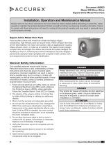
Step 3 - Install End Caps
• Locate the end cap that has a 7/8 inch conduit hole,
this is for running power to the fan
• Determine which side of the unit (inlet or outlet) the
power will be run through
• With flanges away from the fan, align the half moon
cutouts on the end cap with screws on inlet or outlet
• Mount the end cap with conduit hole to the top of the
inlet or outlet depending on where the power will be run,
use provided self-tapping sheet metal screws and 5/16
inch impact driver DO NOT OVER-TIGHTEN
• Install remaining plate on opposite side (inlet or outlet)
using provided self-tapping sheet metal screws and
5/16 inch impact driver DO NOT OVER-TIGHTEN
• TAKE CARE NOT TO DAMAGE THE FOAM TAPE ON
END CAPS
TOP
BOTTOM
1
2
SIZE 7-16
SIZE 18-33
SIZE 7-16
SIZE 18-33
FOAM TAPE
Step 4 - Install Side Mullions (Sizes 18-33 only)
• Install left and right side mullions using (2) self-tapping
sheet metal screws per side
TOP
BOTTOM
1
2
SIZE 7-16
SIZE 18-33
SIZE 7-16
SIZE 18-33
FOAM TAPE
TOP
BOTTOM
1
2
SIZE 7-16
SIZE 18-33
SIZE 7-16
SIZE 18-33
FOAM TAPE
Tools List
• Impact Driver
• 5/16 inch nut driver
• C clamp locking pliers
• Outdoor Cover parts are shipped
separate from the fan and are
mounted in the field
• This Quick Start Guide does not
replace the Installation Operation
Manual (IOM), refer to the IOM for
more information
• (1) Fan
• Outdoor cover kit
(1) End cap with hole
(1) End cap without hole
(2) Mullions (size 18-33 only)
Side panels
(2) Size 7-16
(4) Size 18-33
Top panel(s)
(1) Size 7-16
(2) Size 18-33
Hardware kit
(1) Size 7-16
(2) Size 18-33
(1) Conduit Kit
• (1) Disconnect switch (optional)
• (1) Isolator kit (optional)
• Liquid-tight conduit (supplied
by others)
Parts List
ASSEMBLY VIDEO
SQ MIXED FLOW IOM

485552 • Outdoor Cover, Rev. 2, August 2023 • Copyright © 2023 Greenheck Fan Corp.
Step 5 - Install Side Panels
• Align half moon cutouts on side panels with inlet
and outlet fasteners
• Install one side of outdoor cover to fan with drip
edge down, use provided self-tapping sheet
metal screws and 5/16 inch impact driver
• Repeat for opposite side
TOP
BOTTOM
1
2
SIZE 7-16
SIZE 18-33
SIZE 7-16
SIZE 18-33
FOAM TAPE
• Sizes 18-33 have (2) panels per side, they are
fastened to the mullion, inlet, and outlet plate
Step 6 - Mount Disconnect Switch (if applicable)
• Determine ideal location for disconnect switch
• Install per disconnect manufacturer’s guidelines
Step 7 - Install Conduit
• Connect the provided flexible metal conduit
(FMC) and fitting assembly to the junction box
with power
• Route opposite end of conduit assembly (with
female connector) to hole in end cap.
• Insert liquid-tight connector into hole in end cap
and screw into the female connector, as
shown below
• Cut liquid-tight conduit (supplied by others)
to length and install from elbow to disconnect
switch or power supply
Step 8 - Route Wiring to Junction Box
• Route wiring from junction box on top of fan to
switch through all conduit and fittings
• Connect wiring to motor leads in junction box on
top of the fan, replace the junction box cover
• Connect wiring to disconnect or power supply
• Junction boxes (and “Dial on Fan” if Vari-Green®)
on top of the fan are inaccessible when outdoor
cover is fully installed
Step 9 - Install Top Panel(s)
• Size 7-16:
Install top panel of outdoor cover to fan using
provided self-tapping sheet metal screws
TOP
BOTTOM
1
2
SIZE 7-16
SIZE 18-33
SIZE 7-16
SIZE 18-33
FOAM TAPE
• Sizes 18-33:
1. Install the first top panel with single return
flange using provided self-tapping sheet
metal screws (reference 1 below)
2. Install the second top panel with double
return flange by hinging it around the first
panel as shown (reference 2 below)
3. Use self-tapping sheet metal screws to
mount second panel, filling all holes
TOP
BOTTOM
1
2
SIZE 7-16
SIZE 18-33
SIZE 7-16
SIZE 18-33
FOAM TAPE
• TAKE CARE NOT TO DAMAGE THE FOAM
TAPE ON THESE PARTS
TOP
BOTTOM
1
2
SIZE 7-16
SIZE 18-33
SIZE 7-16
SIZE 18-33
FOAM TAPE
TOP
BOTTOM
1
2
SIZE 7-16
SIZE 18-33
SIZE 7-16
SIZE 18-33
FOAM TAPE
TOP
BOTTOM
1
2
SIZE 7-16
SIZE 18-33
SIZE 7-16
SIZE 18-33
FOAM TAPE
TOP
BOTTOM
1
2
SIZE 7-16
SIZE 18-33
SIZE 7-16
SIZE 18-33
FOAM TAPE
/