Page is loading ...

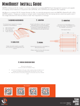
MiniBoostPro Install Guide
TEAM
BMPRO
.COM
2. Additional Required Accessories
1. Description of Parts
3. Location
5. Cable Size
4.Mounting
6. Wiring Considerations
Install the MiniBoostPRO inside your caravan or
camper trailer, preferably close to the house battery.
To ensure optimal operation, install the MiniBoostPRO
in a well-ventilated area with good airflow.
BMPRO’s MiniBoostPRO is a compact Lithium DC-DC charger with solar input, specially designed for the RV market.
The MiniBoostPRO battery charger offers effective charging of your caravan, 4WD or camper trailer’s house battery from
the towing vehicle’s electrical system.
1. Aux LED
2. Solar LED
3. Fault LED
4. Aux In: Connect to primary battery positive terminal.
5. Solar In: Connect to solar panel positive terminal.
6. Batt Out: Connect to charging battery positive terminal.
7. Common Negative: Connect to solar, primary and charging battery
secondary negative terminals.
8. Ignition Detect: Connect to towing vehicle’s ignition.
9. Batt Chemistry: To configure battery chemistry.
The following accessories (not supplied) are required to
complete installation of the MiniBoostPRO:
2 x 40A Automotive Fuse
2 x 2A Automotive Fuse
Securely mount the MiniBoostPRO to a strong,
flat surface. The MiniBoostPRO can be installed in
any position.
To install the DC-DC charger:
1. Choose a strong, flat surface and securely mount the
device on it.
2. Place the charger inside your caravan or camper
trailer, near the house battery.
3. Note: Proper mounting and positioning of the charger
is important for safe and optimal operation.
Cables should be sized to carry 30A.
To ensure safe and reliable wiring:
• Crimp or solder wire connections.
• Use heat shrink to cover all wire
connections and prevent exposed wires.
7. Wiring Diagram If you are using a Power
Management System, connect
the DC-DC charger’s Batt Out
and Common Negative cables
to the positive and negative
primary input.
You can also wire the DC-DC
charger directly to the
secondary battery using a
protective fuse.
CABLE CABLE COLOUR MINIMUM CABLE SIZE
Solar In
Aux In
Batt Out
Common Negative
Ignition
Batt Chemistry
White
Orange
Red
Black
Blue
Green
6.0mm2 or 10 AWG
6.0mm2 or 10 AWG
6.0mm2 or 10 AWG
6.0mm2 or 10 AWG
0.34mm2 or 22 AWG
0.34mm2 or 22 AWG
DOC PART 038640
REV 1.0

TEAM
BMPRO
.COM
8. Fusing
PRODUCT PAGE DATASHEET VIDEO
10. Battery Chemistry Selection
9. Ignition Detect
Fuse protection for the MiniBoostPRO is required on the primary positive
terminals, battery positive terminals, battery chemistry selection cable
and ignition detect cable.
It is recommended for the primary positive and battery positive terminals,
a 40A automotive fuse is used, and for the battery chemistry and ignition
detect cables, a 2A automotive fuse is used.
The fuses must be placed as close to the battery as possible to ensure
optimal protection.
The MiniBoostPRO is equipped with an ignition detect cable, designed to
detect when the vehicle alternator is turned on, and to help prevent your
primary battery from experiencing excessive discharge.
The MiniBoostPRO will start charging the primary battery when the ignition
is detected as on and the primary battery voltage is above 12V. If the
ignition is off or the ignition wire is not installed, the MiniBoostPRO will
start charging when the primary battery voltage is above 12.6V.
Do not connect the ignition cable to the battery positive terminal
indefinitely when the MiniBoostPRO is not charging.
The MiniBoostPRO’s green battery chemistry cable is used to select the
battery chemistry. Setting the correct battery chemistry ensures that the
appropriate voltage levels are set for charging.
11. Charging LED Indicators
12. Fault LED Indicators
IGNITION AUXILIARY VOLTAGE
THRESHOLD
Off
On (+12V)
12.6V
12.0V
FAULT FLASHING
SEQUENCE SOLUTION
Red Single
Flash
Red Flash x 2
Red Flash x3
Red Flash x 4
Red Flash x 5
No source and
secondary battery
voltage <12.1V
Secondary battery
voltage <8V
Secondary battery
voltage >15V
Auxiliary input
voltage >15V
Solar input voltage
>25V
Battery requires charging, connect the
MiniBoostPRO to auxiliary and/or solar
source to begin battery charging
Secondary battery is not connected or
replace with a healthy battery with
voltage between 8-14V
Secondary battery is overcharged or not
a 12V battery. Check power connections
to MiniBoostPRO
Check primary input source with
suitable service provider
Check the solar panel’s open circuit
voltage is between 9 and 25V
BATTERY
CHEMISTRY BULK ABSORPTION
VOLTAGE BATTERY CHEMISTRY
CABLE CONNECTION POINT
Gel
AGM/Wet
LiFePO4
14.2V
14.4V
14.6V
Battery Negative Terminal
Floating/Unconnected
Battery Positive Terminal
SOURCE MODE LED DESCRIPTION
AUX
SOLAR
BLENDING
NONE
Charging
Float
Charging
Float
Solar & Aux
Charging
Float
Battery Good Flashing green light
every 5 seconds
Flashing blue and
green light
Solid blue and green
lights
Flashing blue light,
flashing green light,
solid red light
Solid blue light,
flashing green light,
solid red light
Flashing green light
Solid green light
Blending both solar and auxiliary inputs, the MiniBoostPRO provides a
combined charging current of up to a maximum of 30A, with a
preference to solar. It features proprietary technology designed to
charge from modern car alternators. Moreover, it can be used with
LiFePO4 batteries as well as with traditional lead acid batteries.
The MiniBoostPRO provides a multi stage charging profile.
It functions when wired directly to 12V batteries and enhances
BMPRO’s BatteryPlus35 and J35 battery management systems.
A range of protective features built into the MiniBoostPRO will guard
your caravan or camper trailer’s charging capacity.
This includes a 15 minute delay before charging when the
MiniBoostPRO is wired to the AUX input of the BP35 and J35 battery
management systems.
DOC PART 038640
REV 1.0
/


