Page is loading ...

1
UCS 303 • Setup Guide
IMPORTANT NOTE:
Go to www.extron.com for the complete user guide, installation instructions, and specications before
connecting the product to the power source.
The Unied Communication System (UCS) 303 is a three input, one
output multi-format collaboration switcher with built-in display control that
supports HDMI 2.0b, DisplayPort 1.2, USB 3.2 (SuperSpeed 10 Gbps) and
HDCP 2.3 specications.
The switcher features one HDMI input, one DisplayPort input, one USB-C
input, and one HDMI output with CEC. It also has three USB switched Host
inputs and a built-in USB hub to switch and share USB peripherals such
as USB web cams, touch displays, and USB microphones. Audio can be
extracted from any input.
Resolutions up to 4K @ 60 Hz are supported, along with EDID Minder, HDCP 2.3, and conguration via Product Conguration
Software (PCS) or Extron Simple Instruction Set (SIS) commands. The UCS 303 is housed in a 1U high, half rack wide, 8.5 inches
deep enclosure.
This guide provides instructions for an experienced installer to set up and operate this switching receiver. For full installation,
conguration, and operation details, see the UCS 303 User Guide, available at www.extron.com. In this guide, the terms “UCS,”
“UCS 303,” and “switcher” are used interchangeably to refer to the UCS 303.
Installation Steps
1. Turn o all of the equipment and disconnect the unit from the power source.
2. If desired, mount the switcher on a rack shelf or furniture (mounting kits are available at www.extron.com).
3. Make rear panel connections as needed:
• Video sources and supporting host devices —
• Input 1 — Connect an HDMI source and a supporting host device to the HDMI and associated host input connector
(see gure1, K and B on the next page).
NOTE: LockIt cable lacing brackets are provided to secure the HDMI cables to the ports to reduce stress on the
HDMI connectors and prevent signal loss due to loose cable connections (see Installing LockIt HDMI Cable
Lacing Brackets on page4).
• Input 2 — Connect a DisplayPort source and a supporting host device to the DisplayPort and associated host input
connector (J and B).
• USB-C input — Connect a USB-C source to the rear panel USB-C input connector (I).
• Video output — Connect an HDMI display to the HDMI output (C) to display the transmitted digital image.
• USB peripheral devices — Connect one or more peripheral USB devices (for example, keyboards or mice) to the
USB 3.2 and 2.0 output device ports (D and E) as desired.
NOTE: These ports do not provide power if the connected device is getting power from an external power supply.
• RS-232 display control port — Connect this port (F) to the RS-232 connector of a display to control the display.
• Control port — Connect a computer to either of the following control ports to congure and control the UCS 303 via
PCS or SIS commands:
• Ethernet port — Connect the UCS 303 LAN port (G) to the network via a standard Ethernet cable.
• USB-C CONFIG port — Connect a USB port on the computer to this USB-C connector via a USB Type A to USB-C
cable.
4. Connect power to the IEC power connector (A).

2
5. Congure the switcher using PCS (see the UCS 303 Help File) or SIS commands (see the UCS 303 User Guide) as necessary
for functions such as autoswitching, contact closure, and front panel lock mode.
6. Power on the host devices. The switcher is now ready for operation.
Rear Panel Connections
UCS 303
1
HDMI HDMI/CEC
3
60W
USB-C
OUTPUT
RS-232
Tx Rx G
LAN
100-240V
~
1.2A MAX
50-60Hz
INPUTS
2
DP
DEVICES
CONTACT/TALLY
DISPLAY
34
USB 2.0SS 10G
51 2
CT CT CT CT CT+V G
HOST HOST
12 345
C
C
C
A
A
A
KKK
B
B
BD
D
DE
E
EF
F
F
JJJIIIGGG
HHH
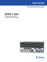
A IEC power connector
D USB SS 10G device ports
G
LAN port J
DisplayPort input
B USB host ports E USB 2.0 device ports
H Contact/Tally ports K
HDMI input
C HDMI output (with CEC)
F Display RS-232 port I USB-C input
Figure 1. UCS 303 Rear Panel
A IEC power connector — Connect a 100-240 VAC IEC power cable to this connector to provide AC power to the switcher.
ATTENTION:
• Do not connect any external power supplies until you have read the Attention notications in the Power Supply
section of the UCS 303 User Guide.
• Ne branchez pas de sources d’alimentation externes avant d’avoir lu les mises en garde dans la section
« Power Supply » du guide utilisateur pour cet UCS 303.
B USB host ports — Connect PCs or other USB host devices to these female USB type B connectors for USB 3.2 input in
support of input 1 (HDMI, see figure1, K) and input 2 (DisplayPort, J).
C HDMI output (with CEC) — Connect an HDMI or DVI (with an appropriate adapter) output device to this connector for HDMI
video with CEC and embedded audio. The output supports resolutions up to 4096x2160 @ 60 Hz, 8-bit, with 4:4:4 chroma
sampling.
NOTE: Use the provided LockIt Lacing Brackets to secure the HDMI connectors (see Installing LockIt HDMI Cable
Lacing Brackets on page4).
D USB SS 10G device ports — Connect USB 3.2, 2.0, or 1.x devices and HIDs (peripherals such as keyboards, mice, or
storage drives) to these blue USB ports. USB 3.2 signals from the inputs are routed to these ports. Each port provides up to 5
V, 900 mA of power to the connected devices.
NOTE: These ports do not provide power if the connected device is receiving power from a separate power supply.
E USB 2.0 device ports — Connect USB 2.0 or 1.x devices to these black USB Type A ports. USB 2.0 and 1.x signals from the
inputs are routed to these ports. Each port provides up to 5 V, 500 mA of power.
NOTE: These ports do not provide power if the connected device is receiving power from a separate power supply.
1
UCS 303 • Setup Guide (Continued)

3
F RS-232 Display control port — Connect a display to this
RS-232 port, which can be configured via PCS to control the
display in modes 0, 1, or 2 (see the UCS 303 User Guide and the
UCS 303 Help File for more information). The image at right
shows how to wire this port.
G LAN port — Connect the switcher to an active network using an
Ethernet cable terminated with an RJ-45 connector.
Default LAN port settings (if DHCP is not enabled):
• Rear panel LAN IP address — 192.168.254.254
• Subnet mask — 255.255.255.0
• Gateway — 0.0.0.0
• DNS — 127.0.0.1
• Front panel USB-C port IP address — 203.0.113.22 at port 2202
• Username — admin
• Password — The product unit serial number. If an absolute system reset (for example, the EZQQQ] SIS command)
is performed, all passwords on this device are reset to extron.
NOTES:
• DHCP is disabled by default.
• If the UCS is set as a DHCP client and cannot locate a DHCP server, the port is set to a link local address.
• All Ethernet interfaces on the UCS 303 support up to 10/100/1000 Mbps (Gigabit Ethernet).
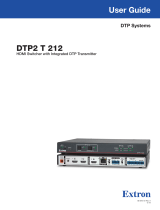
To wire the LAN connector (see gure2):
• Use a straight-through cable for connection to a switch, hub, or router.
• Use a crossover cable or a straight-through cable for connection directly to a PC.
RJ-45
Connector
Insert Twisted
Pair Wires
Pins:
12345678
T568B T568AT568BTIA/EIA-T568B
Crossover Cable
(for direct connection to a PC)
End 1 End 2
Pin Wire Color Pin Wire Color
1 white-orange 1 white-green
2 orange 2 green
3 white-green 3 white-orange
4 blue 4 blue
5 white-blue 5 white-blue
6 green 6 orange
7 white-brown 7 white-brown
8 brown 8 brown
Straight-through Cable
(for connection to a switch, hub, or router)
End 1 End 2
Pin Wire Color Pin Wire Color
1 white-orange 1 white-orange
2 orange 2 orange
3 white-green 3 white-green
4 blue 4 blue
5 white-blue 5 white-blue
6 green 6 green
7 white-brown 7 white-brown
8 brown 8 brown
Figure 2. Wiring for Ethernet Control
H Contact/Tally ports — (Optional) Wire a push-button switch or other contact closure device to pin C (contact) and pin G
(ground) of the 2-pole connectors (see the image below right). These ports are configured via PCS or SIS commands.
• To make input selections via contact closure, short the C pin of each port momentarily to the ground pin (G, see 4 in the
image below, right). Input switching occurs immediately on contact, and not on the release.
Alternatively, wire a Show Me (SM) cable to the C and T pins.
The contact closure ports have the following functions:
Pin Number Function Pin Number Function
1Input 1 4AUX
2Input 2 5AUX
3Input 3 GGround
• Ports 1-3 — (1) These can be congured as a mutually exclusive input group to allow for input switching via SM cables.
The selected input tally illuminates steadily when displayed, or blinks when muted. Optionally, successive contact closures
of the current input can be congured to toggle A/V mute or output sync mute.
If None is selected, contact events broadcast unsolicited SIS responses for action via external control system. Tally ports
are congured via an external control system.
Display
Ground (G)
Receive (Rx)
Transmit (Tx)
Ground (G)
Receive (Rx)
Transmit (Tx)
Bidirectional
Do not tin the wires!
Tx Rx G
RS-232
UCS 303
RS-232 Port
2

4
• Ports 4 and 5 — (See 2 in the Contact Closure image on the previous page) These contact ports can be congured as
follows via PCS:
• None — Contact events broadcast unsolicited SIS responses for action via an external control system. Tally ports are
congured via external control system.
• Single switch — Individual contact input triggers user-dened events (such as Volume Up), along with an optional repeat
rate for press and hold actions (such as ramping volume up several steps). The Tally illuminates when the contact port is
closed.
• Toggle switch — Individual contact input toggles between two sets of user-dened events (such as mute and unmute).
The Tally illuminates when the contact port is closed.
• Group switch — Pairs two contact inputs to act as a mutually exclusive pair, which trigger events such as system on vs.
system o. Tally on the last activated contact remains illuminated.
• +V connector — (3) The +V pin constantly outputs +5 VDC power with 200 mA total (shared between pins). Use this pin
when power is needed for external Tally LEDs, such as those on the Extron CCB 30 contact closure remote.
See the UCS 303 User Guide, available at www.extron.com, for information on contact closure.
I USB-C input — Connect a USB-C source device, such as a laptop or PC, to this USB-C connector.
This port provides up to 60 watts of power to the connected source. If the source requires more than 60 watts, this port keeps
the device functioning but does not charge it. If the source is connected to an external power supply, the UCS 303 does not
send power to it.
J DisplayPort input — Connect a DisplayPort source device to this DP connector. The port supports up to 4k @ 60 Hz, 8-bit
color with 4:4:4 chroma sampling.
K HDMI input — Connect an HDMI (or DVI with appropriate adapters) video input source to this female HDMI port for HDMI
video with embedded audio.
NOTE: LockIt cable lacing brackets secure the HDMI cables to the ports to reduce stress on the HDMI connectors and
prevent signal loss due to loose cable connections (see “Installing LockIt HDMI Cable Lacing Brackets” for installation
instructions).
Installing LockIt HDMI Cable Lacing Brackets
Use the included LockIt lacing brackets to securely fasten the HDMI cables to the
UCS 303 HDMI connectors as follows.
1. Plug the HDMI cable into the rear panel connection.
2. Loosen the HDMI connection mounting screw from the panel enough to allow
the LockIt lacing bracket to be placed over it. The screw does not have to be
removed.
3. Place the LockIt lacing bracket on the screw and against the HDMI connector,
then tighten the screw to secure the bracket.
ATTENTION:
• Do not overtighten the HDMI connector mounting screw. The shield it
fastens to is very thin and can easily be stripped.
• Ne serrez pas trop la vis de montage du connecteur HDMI. Le blindage
auquel elle est attachée est très fin et peut facilement être dénudé.
4. Loosely place the included tie wrap around the HDMI connector and the LockIt
lacing bracket as shown.
5. While holding the connector securely against the lacing bracket, use pliers or similar tools to tighten the tie wrap, then
remove any excess length.
3
3
4
1
2
UCS 303 • Setup Guide (Continued)

5
Conguration
The following options are available to congure the UCS 303:
• Product Configuration Software (PCS) — Extron PCS is available at www.extron.com. Download and install the latest
version to a PC connected to the switcher either via Ethernet or the front panel USB CONFIG port (see gure3, A). For full
instructions while PCS is running, press <F1> on the keyboard, click the ? button in PCS, or select the Help File option from
the PCS Device Tab menu to view the UCS 303 Help File.
• Simple Instruction Set (SIS) commands — The UCS 303 can be congured and controlled via SIS commands when
connected to a host computer or other device (such as a control system). Attach the host device to the rear panel LAN
connector, or to the front panel USB-C CONFIG port. For a list of SIS commands and variables, see the UCS 303 User Guide,
available at www.extron.com.
• Internal web pages — The factory-installed web pages can be used to view device status, perform certain conguration
functions, and set a password. To view this page in a web browser, connect the UCS to a LAN. The default IP address is
192.168.254.254. A password is required the rst time the page is opened and remains in eect until changed or removed.
NOTE: The factory congured passwords for all accounts on this device have been set to the device serial number. An
absolute system reset changes the password setting to extron. Passwords are case sensitive.
Firmware Updates
When new rmware versions become available, download the updates from the Extron website. New rmware versions can be
uploaded using PCS, the internal web page, SIS commands, and the Firmware Loader software, available at www.extron.com
(see the UCS 303 User Guide for details).
Front Panel Features
UCS 303
COLLABORATON SWITCHER
DEVICES
R
INPUTS
OUTPUTINPUTS
AUTO
SWITCH
CONFIG
1 2 3
1 2
HOST
3
HDCP
1 2
SIGNAL
34
5
USB-CUSB
G
G
G
E
E
E
A
A
A
B
B
BC
C
CD
D
DF
F
F
HHH
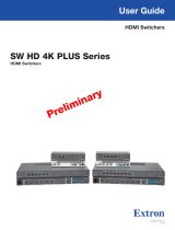
A Power and Reset LED D Input buttons and LEDs G USB-C power LED
B Reset button E Input and output signal and status LEDs H USB-C CONFIG port
C Auto Switch LED F USB status LEDs
Figure 3. UCS 303 Front Panel
A Power and reset LED — Lights when the unit has power. While the R (reset) button (see figure3, B) is pressed and held,
this LED blinks every 3 seconds to indicate the level of reset that is initiated if the button is released and momentarily pressed
again at that point.
B Reset button — Using an Extron Tweeker (provided) or other small screwdriver or stylus, press the R button to reset the unit.
There are three available reset modes:
• Press and hold the Reset button for 3 seconds to return all settings to the factory default, excluding IP settings.
• Press and hold the Reset button for 6 seconds to return all settings to default, including IP settings.
• Press and hold the Reset button while applying power to return all settings to default, and revert the rmware to the
factory installed version.
C Auto Switch LED — Lights when auto-switching is in effect. The switcher can be configured via SIS commands or PCS to
automatically select the lowest to highest numbered input with an active signal.
D Input buttons and LEDs — Press these buttons to select an input to switch to the output. When an input is selected, the LED
at the right of the input button lights. If auto-switching is in effect, the input buttons are disabled, but the LEDs continue to light
to indicate the selected input.
3

UCS 303 • Setup Guide (Continued)
For information on safety guidelines, regulatory compliances, EMI/EMF compatibility, accessibility, and related topics, see the
Extron Safety and Regulatory Compliance Guide on the Extron website.
© 2023 Extron — All rights reserved. www.extron.com All trademarks mentioned are the property of their respective owners.
Worldwide Headquarters: Extron USA West, 1025 E. Ball Road, Anaheim, CA 92805, 800.633.9876
68-3538-50 Rev. B
12 23
6
E Input and output signal and HDCP status LEDs — These stacked green LEDs light as follows:
• SIGNAL LEDs — Light when active video content is detected on the corresponding input or the output.
• HDCP LEDs — Light when the corresponding input or the output signal is HDCP encrypted.
NOTES:
• HDCP is authenticated on each input regardless of the currently selected source.
• If the source device connected to the selected input is HDCP encrypted (requires HDCP authentication), the
corresponding signal LED may not light unless HDCP has been authenticated.
F USB status LEDs — These stacked green LEDs light as follows:
• HOST LEDs — Light to indicate the USB host status for the corresponding input.
• DEVICES LEDs — Light to indicate the status for the corresponding USB device port.
G USB-C power LED — Lights to indicate switcher power delivery to the connected USB-C source.
H USB-C CONFIG port — Connect the computer to this USB-C connector for product configuration using Extron SIS commands
or PCS.
Application Example
Figure 4 shows an example of how the UCS 303 can be connected.
UCS 303
1
HDMIHDMI/CEC
3
60W
USB-C
OUTPUT
RS-232
Tx Rx G
LAN
100-240V
~
1.2A MAX
50-60Hz
INPUTS
2
DP
DEVICES
CONTACT/TALLY
DISPLAY
34
USB 2.0SS 10G
51 2
CT CT CT CT CT+V G
HOST HOST
12 345
USB CHARGER
USB Camera
with Mic
PC
HDMI
Ethernet
USBDP
HDMI
USBUSB
USB-C
(Data/Power/Video)
(Data/Power/Video)
RS-232
Extron
Cable Cubby 100
Cable Access
Enclosure
Extron
UCS 303
Collaboration
Switcher
Displa
y
USB-C
La
ptop
La
ptop
USB
HDMI
Figure 4. Application Example for UCS 303
4
/