Page is loading ...

3.5 to 21 kVA N+1
Inverter
Owner’s Manual
www.mgeups.com

IMPORTANT SAFETY INSTRUCTIONS
SAVE THESE INSTRUCTIONS – This manual contains important instructions for the S4 Inverter
Plant that must be followed during operation of the equipment.
WARNING: Opening enclosures expose hazardous voltages. Always refer
service to qualified personnel only.
ATTENTION: L'ouverture des cabinets expose des tensions dangereuses.
Assurez-vous toujours que le service ne soit fait que par des
personnes qualifiees.
WARNUNG! Das öffnen der Gehäuse legen gefährliche Spannungen bloss.
Service sollte immer nur von qualifizierten Personal durchge-
führt werden.
WARNING: As standards, specifications, and designs are subject to
change, please ask for confirmation of the information given
in this publication.
ATTENTION: Comme les normes, spécifications et produits peuvent chang-
er, veuillez demander confirmation des informations con-
tenues dans cette publication.
WARNUNG! Normen, Spezifizierungen und Pläne unterliegen Anderungen.
Bitte verlangen Sie eine Bestätigung über alle Informationen,
die in dieser Ausgabe gemacht wurden.
Important Safety information
3.5 to 21 kVA N+1 Inverter
page ii
..

NOTE: This equipment has been tested and found to comply with the
limits for a Class A digital device, pursuant to part 15 of the
FCC rules. These limits are designed to provide reasonable
protection against harmful interference when the equipment
is operated in a commercial environment. This equipment
generates, uses, and can radiate radio frequency energy and,
if not installed and used in accordance with the instruction
manual, may cause harmful interference to radio communica-
tions. Operation of this equipment in a residential area is like-
ly to cause harmful interference in which case the user will
be required to correct the interference at user's own expense.
WARNING: To reduce the risk of fire or electric shock, install in a temper-
ature and humidity controlled indoor area free of conductive
contaminant’s.
This equipment is intended only for installations in a
RESTRICTED ACCESS LOCATION.
ATTENTION: Pour réduire le riske d'inccendie ou d'électrocution, installer
dans une enciente intérieure contrôlée en température et
humidité et sans contaminant’s conducteurs.
Ce matériel est destiné seulement pour des installations dans
un EMPLACEMENT RESTREINT d'cAccès.
WARNUNG! Um die Gefahr von Feuer und elektrischem Schock zu
reduzieren, muss das Gerät in einem temperatur - und
feuchtigkeitskontrollierten Raum, frei von leitungsfähigen
Verunreinigungen, installiert werden. Dieses Gerät ist nur für
die Installation an einem Ort mit eingeschränkter
Zugangserlaubnis vorgesehen.
Diese Ausrüstung ist nur für Anlagen in einem
EINGESCHRäNKTEN ZUGRIFF STANDORT bestimmti.
WARNING: HIGH LEAKAGE CURRENT. Earth connection essential before
connecting supply.
ATTENTION: COURANT DE FUITE ELEVE. Raccordement a la terre indis-
pensable avant le raccordement au reseau.
WARNUNG! Hoher Ableitstrom Vor Inbetriebnahme Schutzleiterverbindung
herstellen.
page iii
Owner’s Manual

3.5 to 21 kVA N+1 Inverter
page iv
This manual covers these models:
Product: Rating:
64074 7.0 kVA 120/240 Line to Neutral only
64144 14.0 kVA 120/240 Line to Neutral only
64214 21.0 kVA 120/240 Line to Neutral only
64074H 7.0 kVA 208/240 Line to Line only
64144H 14.0 kVA 208/240 Line to Line only
64214H 21.0 kVA 208/240 Line to Line only
3.5 kVA to 21 kVA Inverter
Owner's Manual
For service call
1-800-523-0142
86-153460-01 C00 06/2003
Copyright © 2003 MGE UPS SYSTEMS, Inc.
All rights reserved. Printed in U.S.A.
MGE UPS SYSTEMS, Inc.
1660 Scenic Avenue
Costa Mesa, CA 92626
(714) 557-1636

Warranty Information
page v
Owner’s Manual
3.5 to 21 kVA N+1 Inverter
Owner’s Manual
Warranty
The liability of MGE UPS SYSTEMS, Inc. hereunder is limited to replacing or repairing at MGE UPS
SYSTEMS, Inc.’s factory or on the job site at MGE UPS SYSTEMS, Inc.’s option, any part or parts which are
defective, including labor, for a period of 12 months from the date of purchase. The MGE UPS SYSTEMS, Inc.
shall have the sole right to determine if the parts are to be repaired at the job site or whether they are to be
returned to the factory for repair or replacement. All items returned to MGE UPS SYSTEMS, Inc. for repair or
replacement must be sent freight prepaid to its factory. Purchaser must obtain MGE UPS SYSTEMS, Inc.’s
Return Materials Authorization prior to returning items. The above conditions must be met if warranty is to be
valid. MGE UPS SYSTEMS, Inc. will not be liable for any damage done by unauthorized repair work, unautho-
rized replacement parts, from any misapplication of the item, or for damage due to accident, abuse, or Act of
God.
In no event shall the MGE UPS SYSTEMS, Inc. be liable for loss, damage, or expense directly or indirectly
arising from the use of the units, or from any other cause, except as expressly stated in this warranty. MGE
UPS SYSTEMS, Inc. makes no warranties, express or implied, including any warranty as to merchantability or
fitness for a particular purpose or use. MGE UPS SYSTEMS, Inc. is not liable for and Purchaser waives any
right of action it has or may have against MGE UPS SYSTEMS, Inc. for any consequential or special damages
arising out of any breach of warranty, and for any damages Purchaser may claim for damage to any property or
injury or death to any person arising out of its purchase of the use, operation or maintenance of the product.
MGE UPS SYSTEMS, Inc. will not be liable for any labor subcontracted or performed by Purchaser for
preparation of warranted item for return to MGE UPS SYSTEMS, Inc.’s factory or for preparation work for field
repair or replacement. Invoicing of MGE UPS SYSTEMS, Inc. for labor either performed or subcontracted by
Purchaser will not be considered as a liability by the MGE UPS SYSTEMS, Inc.
This warranty shall be exclusive of any and all other warranties express or implied and may be modified
only by a writing signed by an officer of the MGE UPS SYSTEMS, Inc. This warranty shall extend to the
Purchaser but to no one else. Accessories supplied by MGE UPS SYSTEMS, Inc., but manufactured by others,
carry any warranty the manufacturers have made to MGE UPS SYSTEMS, Inc. and which can be passed on to
Purchaser.
MGE UPS SYSTEMS, Inc. makes no warranty with respect to whether the products sold hereunder
infringe any patent, U.S. or foreign, and Purchaser represents that any specially ordered products do not
infringe any patent. Purchaser agrees to indemnify and hold MGE UPS SYSTEMS, Inc. harmless from any
liability by virtue of any patent claims where Purchaser has ordered a product conforming to Purchaser’s speci-
fications, or conforming to Purchaser’s specific design.
Purchaser has not relied and shall not rely on any oral representation regarding the Product sold
hereunder and any oral representation shall not bind MGE UPS SYSTEMS, Inc. and shall not be part of any
warranty.
There are no warranties which extend beyond the description on the face hereof. In no event shall MGE
UPS SYSTEMS, Inc. be responsible for consequential damages or for any damages except as expressly stated
herein.
Service and Factory Repair - Call 1 - 800 - 523 - 0142
Direct questions about the operation, repair, or servicing of this equipment to MGE UPS SYSTEMS, Inc.
Technical Support Services. Include the part number and serial number of the unit in any correspondence.
Should you require factory service for your equipment, contact MGE UPS SYSTEMS, Inc. Technical Support
Services and obtain a Return Materials Authorization (RMA) prior to shipping your unit. Never ship equipment
to MGE UPS SYSTEMS, Inc. without first obtaining an RMA.
Proprietary Rights Statement
The information in this manual is the property of MGE UPS SYSTEMS, Inc., and represents a proprietary
article in which MGE UPS SYSTEMS, Inc., retains any and all patent rights, including exclusive rights of use
and/or manufacture and/or sale. Possession of this information does not convey any permission to reproduce,
print, or manufacture the article or articles shown herein. Such permission may be granted only by specific
written authorization, signed by an officer of MGE UPS SYSTEMS, Inc.
IBM, PC-AT, ES/9000, and AS/400 are trademarks of International Business Machines Corporation. MGE
and MGE UPS SYSTEMS are trademarks of MGE UPS SYSTEMS, Inc. Other trademarks that may be used
herein are owned by their respective companies and are referred to in an editorial fashion only.
Revision History
3.5 to 21 kVA N+1 Inverter Owner’s Manual
86-153460-01
Copyright © 2003 MGE UPS SYSTEMS, Inc. All rights reserved Printed in U.S.A.
Revision: A00 ECN-002762 07/2002
B00 ECN#:002873 09/2002
C00 ECN#003170 06/2003

How To Use This Manual:
This manual is designed for ease of use and easy location of information.
To quickly find the meaning of terms used within the text, look to the Glossary.
To quickly find a specific topic, look at the Table of Contents.
This manual uses Note lines and icons to convey important information.
Note lines and icons come in four varieties.
WARNING: Indicates information provided to protect the User and service
personnel against safety hazards and possible equipment
damage.
CAUTION: Indicates information provided to protect the User and serv-
ice personnel against possible equipment damage.
NOTE: Indicates information provided as an operating tip or an
equipment feature.
IMPORTANT: Indicates information provided as an operating instruction or
as a tip.
How To Use This Manual
3.5 to 21 kVA N+1 Inverter
page vi

CAUTION: Record All Serial Numbers
page vii
Owner’s Manual
CAUTION
RECORD ALL SERIAL NUMBERS FOR THE S4 INVERTER
AND COMPONENTS.
THESE SERIAL NUMBERS WILL BE REQUIRED IF YOUR
SYSTEM NEEDS SERVICE. KEEP THIS MANUAL IN A PLACE
WHERE YOU CAN REFERENCE THE SERIAL NUMBERS IF
SERVICE IS REQUIRED!
S4 INVERTER UNIT SERIAL NUMBER: _________________________________________
INVERTER MODULE SERIAL NUMBER: _________________________________________
RECEIVER CABINET SERIAL NUMBER: ________________________________________
ADDITIONAL MODULES SERIAL NUMBERS:
__________________________ ______________________________
__________________________ ______________________________
__________________________ ______________________________
__________________________ ______________________________
__________________________ ______________________________
__________________________ ______________________________
__________________________ ______________________________
__________________________ ______________________________
__________________________ ______________________________
__________________________ ______________________________

(This page left blank intentionally)
3.5 to 21 kVA N+1 Inverter
page viii

page c —i
Owner’s Manual
Contents
description . . . . . . . . . . . . . . . . . . . . . . . . . . . . . . . . . . . . . .page
IMPORTANT SAFETY INSTRUCTIONS . . . . . .Inside Front Cover
Warranty . . . . . . . . . . . . . . . . . . . . . . . . . . . . . . . . . . . . . . . . . . .v
Revision History . . . . . . . . . . . . . . . . . . . . . . . . . . . . . . . . . . . . .v
How To Use This Manual . . . . . . . . . . . . . . . . . . . . . . . . . . . . . .vi
CAUTION: Record all Serial Numbers . . . . . . . . . . . . . . . . . . . .vii
Section 1 Introduction
section description . . . . . . . . . . . . . . . . . . . . . . . . . . . . . . . . . . . . . .page
1.0 Scope . . . . . . . . . . . . . . . . . . . . . . . . . . . . . . . . . . . . . . . . . . .1-1
1.1 General Description . . . . . . . . . . . . . . . . . . . . . . . . . . . . . . . . .1-2
1.2 Standard Products . . . . . . . . . . . . . . . . . . . . . . . . . . . . . . . . . .1-2
1.3 Electrical Specifications . . . . . . . . . . . . . . . . . . . . . . . . . . . . .1-3
1.3.1 DC Input . . . . . . . . . . . . . . . . . . . . . . . . . . . . . . . . . . . . . . . . .1-3
1.3.2 AC Output (per module) . . . . . . . . . . . . . . . . . . . . . . . . . . . . . .1-3
1.4 Mechanical Specification . . . . . . . . . . . . . . . . . . . . . . . . . . . . .1-4
1.5 Environmental Specifications . . . . . . . . . . . . . . . . . . . . . . . . . .1-5
1.5.1 Thermal Dissipation . . . . . . . . . . . . . . . . . . . . . . . . . . . . . . . . .1-5
1.6 Safety Approvals . . . . . . . . . . . . . . . . . . . . . . . . . . . . . . . . . . .1-5
Section 2 Installation and Operation
section description . . . . . . . . . . . . . . . . . . . . . . . . . . . . . . . . . . . . . .page
2.0 Scope . . . . . . . . . . . . . . . . . . . . . . . . . . . . . . . . . . . . . . . . . . .2-1
2.1 Receiving . . . . . . . . . . . . . . . . . . . . . . . . . . . . . . . . . . . . . . . .2-1
2.1.1 Handling . . . . . . . . . . . . . . . . . . . . . . . . . . . . . . . . . . . . . . . . .2-1
2.1.2 Storage . . . . . . . . . . . . . . . . . . . . . . . . . . . . . . . . . . . . . . . . . .2-1
2.2 Prerequisites to Installation . . . . . . . . . . . . . . . . . . . . . . . . . . .2-1
2.3 Mechanical Mounting . . . . . . . . . . . . . . . . . . . . . . . . . . . . . . . .2-2
2.3.1 Location . . . . . . . . . . . . . . . . . . . . . . . . . . . . . . . . . . . . . . . . .2-3
2.4 Wiring Connections Line To Neutral Units . . . . . . . . . . . . . . . .2-4
2.4.1 Grounding . . . . . . . . . . . . . . . . . . . . . . . . . . . . . . . . . . . . . . . .2-4
2.5 Input and Output Cable Connections . . . . . . . . . . . . . . . . . . . .2-4
2.5.1 AC Input Circuit Breaker . . . . . . . . . . . . . . . . . . . . . . . . . . . . .2-4
Contents

Section 2 Installation and Operation (continued)
section description . . . . . . . . . . . . . . . . . . . . . . . . . . . . . . . . . . . . . .page
2.5.2 DC Input . . . . . . . . . . . . . . . . . . . . . . . . . . . . . . . . . . . . . . . . .2-5
2.5.3 DC Input Circuit Breaker . . . . . . . . . . . . . . . . . . . . . . . . . . . . .2-5
2.5.4 Connections . . . . . . . . . . . . . . . . . . . . . . . . . . . . . . . . . . . . . .2-7
2.5.5 AC Input/Output Voltage Selection . . . . . . . . . . . . . . . . . . . . .2-8
2.5.6 EMI Filter Wiring . . . . . . . . . . . . . . . . . . . . . . . . . . . . . . . . . . .2-8
2.6 Software Configuration Set-Up . . . . . . . . . . . . . . . . . . . . . . . . .2-9
2.6.1 Dual Processor Set-Up . . . . . . . . . . . . . . . . . . . . . . . . . . . . . .2-9
2.6.2 System Personalization . . . . . . . . . . . . . . . . . . . . . . . . . . . . . 2-9
2.6.3 Rack kVA Rating ID Label . . . . . . . . . . . . . . . . . . . . . . . . . . .2-10
2.6.4 On-Line Mode . . . . . . . . . . . . . . . . . . . . . . . . . . . . . . . . . . . .2-10
2.6.5 Off-Line Mode . . . . . . . . . . . . . . . . . . . . . . . . . . . . . . . . . . . .2-10
2.7 Wiring Connections Line To Line Units . . . . . . . . . . . . . . . . . .2-11
2.7.1 Grounding . . . . . . . . . . . . . . . . . . . . . . . . . . . . . . . . . . . . . . .2-11
2.8 Input and Output Cable Connections . . . . . . . . . . . . . . . . . . .2-11
2.8.1 AC Input Circuit Breaker . . . . . . . . . . . . . . . . . . . . . . . . . . . .2-11
2.8.2 DC Input . . . . . . . . . . . . . . . . . . . . . . . . . . . . . . . . . . . . . . . .2-11
2.8.3 DC Input Circuit Breaker . . . . . . . . . . . . . . . . . . . . . . . . . . . .2-12
2.8.4 Connections . . . . . . . . . . . . . . . . . . . . . . . . . . . . . . . . . . . . .2-14
2.8.5 AC Input/Output Voltage Selection . . . . . . . . . . . . . . . . . . . .2-14
2.9 Software Configuration Set-Up . . . . . . . . . . . . . . . . . . . . . . . .2-14
2.9.1 Dual Processor Set-Up . . . . . . . . . . . . . . . . . . . . . . . . . . . . .2-14
2.9.2 System Personalization . . . . . . . . . . . . . . . . . . . . . . . . . . . . . 2-14
2.9.3 Rack kVA Rating ID Label . . . . . . . . . . . . . . . . . . . . . . . . . . .2-15
2.9.4 On-Line Mode . . . . . . . . . . . . . . . . . . . . . . . . . . . . . . . . . . . .2-15
2.9.5 Off-Line Mode . . . . . . . . . . . . . . . . . . . . . . . . . . . . . . . . . . . .2-15
2.10 Redundant Controller Set-Up . . . . . . . . . . . . . . . . . . . . . . . . .2-16
2.10.1 Inverter Module Installation . . . . . . . . . . . . . . . . . . . . . . . . . .2-16
2.11 Indicators and Controls . . . . . . . . . . . . . . . . . . . . . . . . . . . . .2-17
2.11.1 LCD Readout . . . . . . . . . . . . . . . . . . . . . . . . . . . . . . . . . . . . .2-17
2.12 Remote Alarm . . . . . . . . . . . . . . . . . . . . . . . . . . . . . . . . . . . .2-19
2.12.1 Alarm Relays . . . . . . . . . . . . . . . . . . . . . . . . . . . . . . . . . . . . .2-19
2.13 Start-Up Sequence . . . . . . . . . . . . . . . . . . . . . . . . . . . . . . . .2-20
2.13.1 Power-up Procedure . . . . . . . . . . . . . . . . . . . . . . . . . . . . . . .2-20
2.13.2 Powering Up the Inverters . . . . . . . . . . . . . . . . . . . . . . . . . . .2-20
2.13.3 De-Energizing the System . . . . . . . . . . . . . . . . . . . . . . . . . . .2-20
Contents
3.5 to 21 kVA N+1 Inverter
page c —ii

Contents
page c —iii
Owner’s Manual
Section 3 Maintenance Adjustment and Troubleshooting
section description . . . . . . . . . . . . . . . . . . . . . . . . . . . . . . . . . . . . . .page
3.0 Scope . . . . . . . . . . . . . . . . . . . . . . . . . . . . . . . . . . . . . . . . . . .3-2
3.1 Safety Instructions for Servicing . . . . . . . . . . . . . . . . . . . . . . . .3-2
3.2 Preventative Maintenance . . . . . . . . . . . . . . . . . . . . . . . . . . . .3-2
3.3 Equipment Adjustment and Calibration . . . . . . . . . . . . . . . . . . .3-3
3.4 Air Intake Cleaning . . . . . . . . . . . . . . . . . . . . . . . . . . . . . . . . .3-3
3.5 AC Fan Replacement . . . . . . . . . . . . . . . . . . . . . . . . . . . . . . .3-3
3.6 DC Fan Replacement . . . . . . . . . . . . . . . . . . . . . . . . . . . . . . .3-3
3.7 Replacement Parts . . . . . . . . . . . . . . . . . . . . . . . . . . . . . . . . .3-4
3.8 Redundant Microprocessor
(72-153588-00) Installation/Configuration . . . . . . . . . . . . . . . .3-5
3.9 Troubleshooting and Servicing . . . . . . . . . . . . . . . . . . . . . . . . .3-6
3.9.1 Installation Check . . . . . . . . . . . . . . . . . . . . . . . . . . . . . . . . . .3-6
3.10 AC Output Circuit Breaker . . . . . . . . . . . . . . . . . . . . . . . . . . . .3-6
3.10.1 Cable Connection and Static Switch Module . . . . . . . . . . . . . .3-6
3.11 Troubleshooting Guide . . . . . . . . . . . . . . . . . . . . . . . . . . . . . . .3-7
Glossary g—1

Figures
figure description . . . . . . . . . . . . . . . . . . . . . . . . . . . . . . . . . . . . . . . .page
1-1 System Configurations. (N+1 = added redundancy) . . . . . . . . . . . 1-2
2-1 Installation Drawing, 7 kVA Inverter System . . . . . . . . . . . . . . . . .2-2
2-2 Front View, 7 kVA, System Component Description . . . . . . . . . . . .2-3
2-3 Line To Neutral Inverter Receiver Junction Box . . . . . . . . . . . . . . .2-5
2-3a Static Switch Section - Input and Output Wiring . . . . . . . . . . . . . . .2-6
2-4 EMI and Busbar VAC Configurations . . . . . . . . . . . . . . . . . . . . . . .2-7
2-5 Line To Neutral Setup Screen . . . . . . . . . . . . . . . . . . . . . . . . . . . .2-9
2-6 Line To Line Inverter Receiver Junction Box . . . . . . . . . . . . . . . . .2-12
2-6a Static Switch Section - Input and Output Wiring . . . . . . . . . . . . . .2-13
2-7 Line To Line Setup Screen . . . . . . . . . . . . . . . . . . . . . . . . . . . . . .2-15
2-8 Inverter Module . . . . . . . . . . . . . . . . . . . . . . . . . . . . . . . . . . . . .2-16
2-9 S4 Inverter Components . . . . . . . . . . . . . . . . . . . . . . . . . . . . . . .2-18
3-1 Redundant Microprocessor Component Location . . . . . . . . . . . . . .3-5
Tables
table description . . . . . . . . . . . . . . . . . . . . . . . . . . . . . . . . . . . . . . . .page
1-1 Inverter System Characteristics . . . . . . . . . . . . . . . . . . . . . . . . . . .1-2
1-2 Inverter Module Dimensions . . . . . . . . . . . . . . . . . . . . . . . . . . . . .1-3
1-3 S4 AC Output Current Ratings (with resistive load) . . . . . . . . . . . .1-3
1-4 S4 Receiver Cabinet Mechanical Dimensions and Weights . . . . . .1-4
2-1 Line To Neutral Units Suggested Circuit Breaker Ratings . . . . . . . .2-4
2-2 Line To Neutral Units Suggested DC Circuit Breaker Ratings . . . . .2-5
2-3 Line To Line Units Suggested Circuit Breaker Ratings . . . . . . . . .2-11
2-4 Line To Line Units Suggested DC Circuit Breaker Ratings . . . . . .2-12
2-5 Alarm Connections . . . . . . . . . . . . . . . . . . . . . . . . . . . . . . . . . . .2-17
3-1 Spare Parts and Kits . . . . . . . . . . . . . . . . . . . . . . . . . . . . . . . . . . .3-4
3-2 Troubleshooting table . . . . . . . . . . . . . . . . . . . . . . . . . . . . . . . . . .3-7
Contents
3.5 to 21 kVA N+1 Inverter
page c —iv

WARNING: An AC output will be present at the output terminals immedi-
ately when AC input is energized.
ATTENTION: La tension alternative de sortie appara ît dès la mise sous ten-
sion de l'entrée.
WARNUNG! Eine Ausgangsspannung liegt an den Ausgangsklemmen,
sobald der Netzeingang angeschlossen wird.
1.0 Scope
This manual provides technical information for installation, operation, and maintenance of MGE inverter systems
series ranging from 3.5 kVA to 21 kVA. Please read this manual thoroughly before installing and operating the sys-
tem. Please retain this manual for future reference.
The manual is divided into three sections:
Section 1 Introduction
This section introduces the 3.5 to 21 kVA static inverters, including a general description of the invert-
er, its components, and specifications.
Section 2 Installation & Operation
This section describes installation of the inverters, including receiving, handling, and storage proce-
dures; prerequisites to the installation; installation procedures; and start-up procedures.
Section 3 Maintenance
This section describes the maintenance and service of the S4 Inverter, including safety instructions,
preventive maintenance, descriptions of replacement kits, and a troubleshooting table.
Owner’s Manual
Introduction
Introduction
page 1 — 1

1.1 General Description
This static, modular inverter system series provide stable, distortion-free AC power from a DC input source at a
selectable output voltage and frequency prior to shipment, for sensitive equipment. With a built-in static transfer
switch, the inverter also forms a reliable and economical part of uninterruptible power supply systems in either on-
line or off-line mode. This series employed modular design to provide N+1 redundancy, and twin controller cards
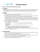
to double reliability. There are three distinctive parts in these tower inverter systems. The top part is a built-in mod-
ule that houses the twin controller, alarm cards, LCD unit, and LED indicators. The center part is a built-in module
that houses a static transfer switch, and where input and output connectors are located. It is easily recognized by
a twin fan front panel. Above and below this static switch module are individual inverter modules rated 3.5 kVA/3kW
each (those with single fan front panel).
S4 inverters are available in three receiver cabinet configurations housing 1 to 6 inverters, a static transfer switch
console, and redundant microcontroller modules.
Figure 1-1: System Configurations. (N+1 = added redundancy).
7 kVA/3.5 kVA N+1 14 kVA/10.5 kVA N+1 21 kVA/17.5 kVA N+1
1.2 Standard Products
Consult table 1-1 below for the system(s) you are working on.
Table 1-1: Inverter System Characteristics.
Part Power Nominal Input Maximum Maximum Output Selectable
Number rating Input Voltage Input Current Amperes at selectable Output
(kVA) Voltage Range @ -40VDC output voltage of: Frequency
(VDC) (VDC) (Amperes) 120 208-240 Hz
64074/H 7 (-48) (-40 to -60) 176 58 29 50 or 60
64144/H 14 (-48) (-40 to -60) 353 116 58 50 or 60
64214/H 21 (-48) (-40 to -60) 529 174 87 50 or 60
REMOVING MODULE
!
OPEN BREAKER BEFORE
WARNING!
DC INPUT
GREEN = NORMAL
YELLOW = WARNING
RED = FAULT
STATUS
TEMPERATURE
POWER MODULE
REMOVING MODULE
!
OPEN BREAKER BEFORE
WARNING!
DC INPUT
GREEN = NORMAL
YELLOW = WARNING
RED = FAULT
STATUS
TEMPERATURE
POWER MODULE
REMOVING MODULE
!
OPEN BREAKER BEFORE
WARNING!
DC INPUT
GREEN = NORMAL
YELLOW = WARNING
RED = FAULT
STATUS
TEMPERATURE
POWER MODULE
REMOVING MODULE
!
OPEN BREAKER BEFORE
WARNING!
DC INPUT
GREEN = NORMAL
YELLOW = WARNING
RED = FAULT
STATUS
TEMPERATURE
POWER MODULE
REMOVING MODULE
!
OPEN BREAKER BEFORE
WARNING!
DC INPUT
GREEN = NORMAL
YELLOW = WARNING
RED = FAULT
STATUS
TEMPERATURE
POWER MODULE
REMOVING MODULE
!
OPEN BREAKER BEFORE
WARNING!
DC INPUT
GREEN = NORMAL
YELLOW = WARNING
RED = FAULT
STATUS
TEMPERATURE
POWER MODULE
REMOVING MODULE
!
OPEN BREAKER BEFORE
WARNING!
DC INPUT
GREEN = NORMAL
YELLOW = WARNING
RED = FAULT
STATUS
TEMPERATURE
POWER MODULE
REMOVING MODULE
!
OPEN BREAKER BEFORE
WARNING!
DC INPUT
GREEN = NORMAL
YELLOW = WARNING
RED = FAULT
STATUS
TEMPERATURE
POWER MODULE
REMOVING MODULE
!
OPEN BREAKER BEFORE
WARNING!
DC INPUT
GREEN = NORMAL
YELLOW = WARNING
RED = FAULT
STATUS
TEMPERATURE
POWER MODULE
REMOVING MODULE
!
OPEN BREAKER BEFORE
WARNING!
DC INPUT
GREEN = NORMAL
YELLOW = WARNING
RED = FAULT
STATUS
TEMPERATURE
POWER MODULE
REMOVING MODULE
!
OPEN BREAKER BEFORE
WARNING!
DC INPUT
GREEN = NORMAL
YELLOW = WARNING
RED = FAULT
STATUS
TEMPERATURE
POWER MODULE
REMOVING MODULE
!
OPEN BREAKER BEFORE
WARNING!
DC INPUT
GREEN = NORMAL
YELLOW = WARNING
RED = FAULT
STATUS
TEMPERATURE
POWER MODULE
Introduction
3.5 to 21 kVA N+1 Inverter
page 1 — 2

Introduction
page 1 — 3
Owner’s Manual
Table 1-2: Inverter Module Dimensions.
Inverter Module HEIGHT (in/cm) DEPTH (in/cm) WIDTH (in/cm) WEIGHT (lb/kg)
64004-9MSK1 5.18 / 13.16 15.12 / 38.4 15.76 / 40.03 46 / 20.86
Note: Weight: Six-mod receiver = 135 lbs. (61.2 kg) 1 UPS Module = 46 lbs. (20.09 kg)
Total System Weight, 21 kVA system = 411 lbs. (186.4 kg)
1.3 Electrical Specifications
Electrical Specifications are subject to revision without notice.
1.3.1 DC Input
Nominal: -48Vdc; Operating Range: -39.5Vdc to -57 Vdc
NOTE: An external DC circuit breaker or fuse should be used at the DC
source.
1.3.2 AC Output (per module)
Voltage: 120Vrms or 240Vrms
Current: 25Arms or 12.5Arms
Frequency: 60Hz or 50Hz
Table 1-3: S4 AC Output Current Ratings.
Attention: Watts rating = 85% of the VA rating at 120/240 VAC.
MAXIMUM OUTPUT RATINGS
7 KVA unit 14 KVA unit 21 KVA unit
Vout Iout Output Output Iout Output Output Iout Output Output
(Vac) (A) Power VA (A) Power VA (A) Power VA
(W) (VA) (W) (VA) (W) (VA)
110 58.33 6000 6416 116.66 12000 12833 175 18000 19250
115 58.33 6000 6708 116.66 12000 13416 175 18000 20125
120 58.33 6000 7000 116.66 12000 14000 175 18000 21000
208 29.165 6000 6066 58.33 12000 12133 87.5 18000 18200
220 29.165 6000 6416 58.33 12000 12833 87.5 18000 19250
230 29.165 6000 6708 58.33 12000 13416 87.5 18000 20125
240 29.165 6000 7000 58.33 12000 14000 87.5 18000 21000
Units configured to other then 120/240VAC are derated due to current limit.
The % Load reading on the display panel is always with reference to the 120/240 Vac WATT and VA ratings.

Efficiency 85% minimum, 88% typical (on-line mode); 97% typical (off-line mode) at full kVA/Watt load.
Power Factor Rated kVA is available over a power factor range of 0.6 lagging to 0.6 leading at nominal volt-
age. Watt rating should not be exceeded.
Total Harmonic
Distortion Less than 1% for linear load conditions, 3% maximum for crest factor loads up to 3:1.
Line Regulation System output voltage variation, less than 1% over the DC voltage range.
Load Regulation System output voltage variation, less than 1% from zero to full load at nominal DC input.
Output Frequency User-selectable, 50Hz or 60Hz. Free run frequency stability shall be within +/-0.02% of the
selected frequency.
Short Circuit Current (SCC)300% minimum of rated load current for four cycles. A SCC is defined as a current that
exceeds 150% of rated current.
Overload Capability Continuous overload up to 108% of rated VA/watts at 50°C maximum.
Transient Deviation
and Recovery Within 20% of average value for any change in output current or step change in input
voltage within specified limits. Recovery within 1 millisecond from zero to full load.
EMI Emission Battery Bus less than 30dBrnc. FCC 47 CFR part 15 class A; EN 55022 class A;
CISPR 22 class A
1.4 Mechanical Specifications
Table 1-4: S4 Receiver Cabinet Mechanical Dimensions and Weights
MODEL
7 kVA 14 kVA 21 kVA
HEIGHT (in/cm) 21 / 54 31.5 / 81 42 / 107.9
DEPTH (in/cm) 18.5 / 47.5 18.5 / 47.5 18.5 / 47.5
WIDTH (in/cm) 17 / 43.7 17 / 43.7 17 / 43.7
RECEIVER WEIGHT (lb/kg) 88 / 39.9 111 / 50.3 136 / 61.7
RECEIVER + MODULES 182 / 82.6 299 / 135.6 418 / 189.6
WEIGHT (lb/kg)
RECEIVER SHIPPING 100 / 45.4 123 / 55.8 148 / 67.1
WEIGHT (lb/kg)
Introduction
3.5 to 21 kVA N+1 Inverter
page 1 — 4

Introduction
page 1 — 5
Owner’s Manual
1.5 Environmental Specifications
Operating Temperature All models operate to specifications from -5°C to +50°C (+23°F to +122°F) for alti-
tude up to 3,300 feet (1006 Meters), and -5°C to 35°C (+23°F to + 95°F) for up
to 13,300 feet (4054 Meters).
Shipping Temperature -40°C to +75°C (-40°F to +192°F) for shipping; Not recommended for storage.
Storage Temperature -40°C to +60°C (-40°F to +166°F).
Operating Humidity 0 to 90% relative, without condensation.
Operating Altitude 200 feet below to 13,300 feet (4054 Meters) above sea level.
Audible Noise Less than 59 dBA per Type 2, IEC and ANSI SI.4, when measured in a 40 dBA
environment at a distance of 4 feet from any surface.
Cooling Cooling is by forced air. Air intake is through the front of the unit, exhaust out the
sides.
1.5.1 Thermal Dissipation
Heat rejection: 602.28 BTU/Hr for each rated KW of the inverter system. This is based on an inverter efficiency of
85% at full load and does not include load dissipation.
kVA rating 71421
Watts 1059 2118 3177
BTU/Hr 3614 7227 10841
Est. A/C, TONS 0.301 0.602 0.903
1.6 Safety Approvals
Meets UL/CSA 60950 (listed) and European Standard EN60950.

(This page left blank intentionally.)
Introduction
3.5 to 21 kVA N+1 Inverter
page 1 — 6

IMPORTANT: Equipment is factory set to operate at 120VAC for Line to
Neutral and 240VAC for Line to Line units. Please read
installation procedure to configure for Line to Neutral and
240VAC for Line to Line units other configurations.
2.0 Scope
This section describes installation of the inverters, including receiving, handling, and storage procedures, prerequi-
sites to the installation, installation procedures, and start-up procedures.
2.1 Receiving
Before accepting the shipment from the freight carrier, inspect the exterior surfaces of all shipping containers or
packaging used, and the equipment, for damage that may have occurred during transit. If the shipping containers
or equipment shows evidence of damage, note the damage on the receiving document (bill of lading) prior to sign-
ing for receipt of equipment.
ALL CLAIMS FOR SHIPPING DAMAGE MUST BE FILED DIRECTLY WITH THE CARRIER. Replacements for
damaged components should be ordered through MGE UPS SYSTEMS.
2.1.1 Handling
IMPORTANT: A spread bar must be used, to avoid bending the bolts or side
panels, if the S4 Inverter is to be lifted from the top using the
eye-bolts.
The equipment can be lifted from the top, using the eye-bolts; however, a spreader bar must be used to avoid bend-
ing the bolts or the side panels. The equipment may also be handled using a forklift or pallet mover.
2.1.2 Storage
If the equipment is to be stored prior to installation, it should be stored in a cool, dry, well-ventilated location that is
protected from rain, splashing water, chemical agents, etc. The equipment should be covered with a tarpaulin or
plastic wrapper to protect it against dust, dirt, paint, or other foreign materials.
2.2 Prerequisites to Installation
An efficient installation depends on careful planning and site preparation. Installation of the equipment must be han-
dled by skilled technicians and electricians familiar with the special requirements of high-voltage electrical equip-
ment. The installation must comply with the requirements of the National Electrical Code (ANSI/NFPA 70, latest
issue) and local codes as applicable.
We strongly recommend contracting MGE for system start-up. Do not allow unqualified personnel to handle, install,
or operate MGE UPS SYSTEMS static inverter systems.
NOTE: The inverter can be mounted close to a rear wall, because there
is no rear access to the unit. All input DC, output AC, and input
AC wiring to the inverter enters through the top or left side of the
rack assembly. Service to the inverter rack is through the front.
If a maintenance bypass unit or junction box is installed, rear
access is required for this unit.
Owner’s Manual
Installation & Operation
Installation and Operation
page 2 — 1

2.3 Mechanical Mounting
The equipment can be floor mounted or rack mounted in a 19” (48.3 cm), 23” (58.4 cm), or 25” (63.5 cm) rack.
Optional mounting bracket kits can be ordered for rack mounting in a 25” (63.5 cm) or 26” (66.0 cm) rack.
All receivers and inverter power modules are shipped separately from the factory. Receivers will be shipped on a
pallet. These receivers can be secured to a floor or to some other permanent base using one-half inch bolts through
the four holes in the base supports. The inverter modules will be shipped based on customer’s discretion on power
configuration or the size of the receiver they are using. Modules will be shipped separately from exterior chassis.
Refer to Figure 2-2 on page 2—3.
Figure 2-1: Installation Drawing, 7 kVA Inverter System.
Installation & Operation
3.5 to 21 kVA N+1 Inverter
page 2 — 2
FOR 1" (2.54 cm),
1-1/2" (3.81cm)
CONDUITS
FOR 1" (2.54 cm),
2" (5.08 cm), 3" (7.62 cm)
CONDUITS
FOR 1/2" (1.27 cm), 3/4" (1.90 cm)
CONDUITS (2 PLACES)
12.210
(31.00 cm)
1.650 (4.19 cm)
3.250
(8.26 cm)
2.825 (17.18 cm)
8.870
(22.53 cm )
16.060
(40.80)
15.775
(40.07 cm)
11.675
(29.65 cm)
8.925
(22.67 cm)
FOR 1" (2.54 cm),
2" (5.08 cm), 3" (7.62 cm)
CONDUITS
FOR 1" (2.54 cm),
1-1/2" (3.81cm)
CONDUITS
TOP VIEW
LEFT SIDE VIEW
/