Miller MPS-10T Owner's manual
- Category
- Welding System
- Type
- Owner's manual
This manual is also suitable for

®
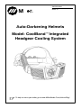
Auto-Darkening Helmets
Model: CoolBandtIntegrated
Headgear Cooling System
OM-235 369A
2009−11
To help us serve you better, go to www.MillerWelds.Com/HelmetReg/

TABLE OF CONTENTS
SECTION 1 − HELMET COOLER SAFETY PRECAUTIONS − READ BEFORE USING 1. . . . . .
1-1. Symbol Usage 1. . . . . . . . . . . . . . . . . . . . . . . . . . . . . . . . . . . . . . . . . . . . . . . . . . . . . . . . . . . . .
1-2. Hazards 1. . . . . . . . . . . . . . . . . . . . . . . . . . . . . . . . . . . . . . . . . . . . . . . . . . . . . . . . . . . . . . . . . .
SECTION 2 − BATTERY SAFETY PRECAUTIONS − READ BEFORE USING 3. . . . . . . . . . . . . .
2-1. Symbol Usage 3. . . . . . . . . . . . . . . . . . . . . . . . . . . . . . . . . . . . . . . . . . . . . . . . . . . . . . . . . . . . .
2-2. Hazards 3. . . . . . . . . . . . . . . . . . . . . . . . . . . . . . . . . . . . . . . . . . . . . . . . . . . . . . . . . . . . . . . . . .
SECTION 3 − HEADGEAR COOLING SYSTEM 5. . . . . . . . . . . . . . . . . . . . . . . . . . . . . . . . . . . . . . .
3-1. Helmet Cooling System Specifications 6. . . . . . . . . . . . . . . . . . . . . . . . . . . . . . . . . . . . . . . . .
3-2. Installing Headgear 7. . . . . . . . . . . . . . . . . . . . . . . . . . . . . . . . . . . . . . . . . . . . . . . . . . . . . . . . .
3-3. Installing Head Shroud 8. . . . . . . . . . . . . . . . . . . . . . . . . . . . . . . . . . . . . . . . . . . . . . . . . . . . . .
3-4. Charging The Battery 9. . . . . . . . . . . . . . . . . . . . . . . . . . . . . . . . . . . . . . . . . . . . . . . . . . . . . . .
3-5. Installing The Battery 10. . . . . . . . . . . . . . . . . . . . . . . . . . . . . . . . . . . . . . . . . . . . . . . . . . . . . .
3-6. Installing The Air Filter 10. . . . . . . . . . . . . . . . . . . . . . . . . . . . . . . . . . . . . . . . . . . . . . . . . . . . .
3-7. Removing Air Deflector To Adjust Air Flow 11. . . . . . . . . . . . . . . . . . . . . . . . . . . . . . . . . . . .
3-8. Operating The Controls 12. . . . . . . . . . . . . . . . . . . . . . . . . . . . . . . . . . . . . . . . . . . . . . . . . . . .
3-9. Checking The Helmet Cooling System Before Use 13. . . . . . . . . . . . . . . . . . . . . . . . . . . . .
3-10. Operating Helmet Cooling System On 120 Volt AC Power 14. . . . . . . . . . . . . . . . . . . . . . .
SECTION 4 − MAINTENANCE 15. . . . . . . . . . . . . . . . . . . . . . . . . . . . . . . . . . . . . . . . . . . . . . . . . . . . .
4-1. Adjusting Headgear 15. . . . . . . . . . . . . . . . . . . . . . . . . . . . . . . . . . . . . . . . . . . . . . . . . . . . . . .
4-2. Replacing Fabric Headband 16. . . . . . . . . . . . . . . . . . . . . . . . . . . . . . . . . . . . . . . . . . . . . . . .
4-3. Maintenance And Storage 17. . . . . . . . . . . . . . . . . . . . . . . . . . . . . . . . . . . . . . . . . . . . . . . . . .
4-4. Helmet Cooling System Troubleshooting 17. . . . . . . . . . . . . . . . . . . . . . . . . . . . . . . . . . . . . .
SECTION 5 − PARTS LIST 19. . . . . . . . . . . . . . . . . . . . . . . . . . . . . . . . . . . . . . . . . . . . . . . . . . . . . . . . .
SECTION 6 − LIMITED WARRANTY 20. . . . . . . . . . . . . . . . . . . . . . . . . . . . . . . . . . . . . . . . . . . . . . . .

OM-235 369 Page 1
SECTION 1 − HELMET COOLER SAFETY PRECAUTIONS −
READ BEFORE USING
Protect yourself and others from injury — read and follow these precautions.
1-1. Symbol Usage
Helmet Cooler 2009−11
This group of symbols means Warning! Watch
Out! ELECTRIC SHOCK, MOVING PARTS,
and HOT PARTS hazards. Consult symbols
and related instructions below for necessary
actions to avoid the hazards.
. Indicates special instructions.
DANGER! − Indicates a hazardous
situation which, if not avoided, will
result in death or serious injury. The
possible hazards are shown in the
adjoining symbols or explained in
the text.
Indicates a hazardous situation
which, if not avoided, could result in
death or serious injury. The possible
hazards are shown in the adjoining
symbols or explained in the text.
NOTICE − Indicates statements not related to
personal injury.
1-2. Hazards
Only qualified persons should install, operate, maintain, and repair this unit.
READ INSTRUCTIONS.
D Read and follow all labels and the Owner’s Manual carefully before installing,
operating, or servicing unit. Read the safety information at the beginning of
the manual and in each section.
D Use only genuine replacement parts from the manufacturer.
D Perform maintenance and service according to the Owner’s Manuals, industry standards,
and national, state, and local codes.
HELMET COOLER MISUSE can be hazardous.
Welding produces fumes and gases. Breathing these fumes and gases can be haz-
ardous to your health.
D Read and follow these instructions and the safety labels carefully. This
product is intended for use as a cooling device only. It is not a respiratory protective device and
does not protect the user from airborne contaminants. Have an industrial hygienist test the air in
your facility to determine if respiratory protection is required to provide adequate protection from
contaminants in your environment. With cooling system-equipped helmet on your head and cool-
ing system operating, also test the air inside the helmet to determine if respiratory protection is re-
quired. If you have questions about the type of respiratory protection equipment required, consult
your safety director and an Industrial Hygienist.
D Do not use this product where there is danger of fire or explosion.
D Do not use this product in windy conditions or negative pressure inside the hood may draw in
contaminants from the outside air.
D Do not use this product without a properly installed spark guard unless the unit is designed and
intended to be used without one. Without the spark guard (on applicable products), welding
sparks may ignite the filter or damage the filter.
D This product does not supply oxygen. Do not use this product where oxygen levels are 19.5% or
lower, where contaminant levels are unknown or are immediately dangerous to life or health
(IDLH), or where the contaminant levels exceed the equipment specifications.
D Do not enter a work area until you are sure the equipment is correctly assembled, working proper-
ly, and properly worn.

OM-235 369 Page 2
D Before each use, inspect the equipment for damage and verify it operates properly.
D Dangerous contaminants may not smell or be visible. Leave the area immediately if you notice
the following:
Breathing becomes difficult.. . .
You experience dizziness, impaired vision, or eye, nose, or mouth irritation.. . .
The equipment is damaged.. . .
D Do not repair, modify, or disassemble this product or use with parts or accessories not supplied by
the manufacturer.
D Do not operate unit without properly installed filter(s). Replace damaged or clogged filters. Do not
wash or reuse filters. Do not clean filters by tapping or with compressed air or filter elements may
be damaged.
D Do not restrict or alter helmet cooler air flow. Do not block air inlet or outlet. Be sure safety
glasses, hair, weld cap, and other objects do not block air flow.
D This product contains electrical parts which have not been evaluated as an ignition source in
flammable or explosive atmospheres by MSHA/NIOSH.

OM-235 369 Page 3
SECTION 2 − BATTERY SAFETY PRECAUTIONS −
READ BEFORE USING
Protect yourself and others from injury — read and follow these precautions.
2-1. Symbol Usage
Small Batt 2009−11
This group of symbols means Warning! Watch
Out! ELECTRIC SHOCK, MOVING PARTS,
and HOT PARTS hazards. Consult symbols
and related instructions below for necessary
actions to avoid the hazards.
. Indicates special instructions.
DANGER! − Indicates a hazardous
situation which, if not avoided, will
result in death or serious injury. The
possible hazards are shown in the
adjoining symbols or explained in
the text.
Indicates a hazardous situation
which, if not avoided, could result in
death or serious injury. The possible
hazards are shown in the adjoining
symbols or explained in the text.
NOTICE − Indicates statements not related to
personal injury.
2-2. Hazards
Only qualified persons should install, operate, maintain, and repair this unit.
FIRE OR BATTERY EXPLOSION hazard.
D During operation keep everyone, especially children, away.
D Do not install or place charger on, over, or near combustible surfaces.
D Do not charge battery near flammables.
D Examine the battery before first use. Return battery to the manufacturer if bat-
tery is damaged, dirty, or emits an unusual odor.
D Use battery only with equipment with which it was supplied. Replace battery
only with battery specified in Owner’s Manual. Use of another battery may
present a risk of fire or explosion.
D Keep battery dry.
D Do not use or store the battery in extremely hot or humid conditions. See the Owner’s Manual
for specific operating and storage information.
D Keep battery away from fire, out of direct sunlight, and away from other sources of heat.
D Do not use or charge the battery if it has been dropped or damaged.
D Do not open, puncture, repair, disassemble, or modify the battery.
D Charge battery only with supplied charger in an open, well−ventilated location out of direct sun-
light and according to supplied instructions.
D Do not overcharge a battery or charge battery longer than specified (if charger is not equipped
with automatic shutoff). See the Owner’s Manual for specific information on battery charging.
D Do not charge battery by connecting directly to AC receptacle. Do not connect battery charger
to automobile auxiliary power receptacle.
D Do not connect (short circuit) battery terminals to each other. Do not allow tools, conductive
materials, or other objects to touch both battery terminals at the same time.
D Do not weld on battery or fasten any objects to battery.
D Do not heat battery in a microwave oven or any other heating device.
D Keep battery away from sources of high voltage.
D Do not expose battery to static electricity.
D Do not use or mix battery with damaged or worn out batteries, or other types of batteries.

OM-235 369 Page 4
BATTERY ACID can BURN SKIN and EYES.
D Replace damaged battery.
D Do not touch materials from inside a damaged battery.
D Flush eyes and skin immediately with water.
READ INSTRUCTIONS.
D Read and follow all labels and the Owner’s Manual carefully before before
using the battery or battery charger. Read the safety information at the be-
ginning of the manual and in each section.
D Dispose of battery according to local, state, and federal requirements. Do not dispose of bat-
tery in fire or water.
D Contact the equipment manufacturer if you have any questions about the battery.

OM-235 369 Page 5
SECTION 3 − HEADGEAR COOLING SYSTEM
Read and follow these instructions and the safety labels carefully. This product is in-
tended for use as a cooling device only. It is not a respiratory protective device and does
not protect the user from airborne contaminants. Have an industrial hygienist test the air
in your facility to determine if respiratory protection is required to provide adequate
protection from contaminants in your environment. With cooling system-equipped hel-
met on your head and cooling system operating, also test the air inside the helmet to
determine if respiratory protection is required. If you have questions about the type of res-
piratory protection equipment required, consult your safety director and an Industrial
Hygienist.
. Use the cooling system only with compatible Miller welding helmets (MP-10, Pro-Hobby,
Performance, Elite, Titanium series helmets). See the welding helmet Owner’s Manual for
information on helmet operation.
The CoolBandt headgear cooling system draws in air and blows it to the front of the welding helmet
through a flexible tube. The system also generates a positive air pressure to help prevent contami-
nants from entering the helmet. The system must include and/or be used with the equipment listed
below:
D Helmet and head shroud
D Blower assembly with properly-installed filter
D Battery charger with AC power adapter
The helmet cooling system operates at temperatures from 14° to 131° F (−10° to 55° C) The Battery
Level red light flashes and blower assembly pulses on and off when battery power is low.
. To better show components
and features, the helmet cool-
ing system is shown without
welding helmet.

OM-235 369 Page 6
3-1. Helmet Cooling System Specifications
Application Fits Most Miller Welding Helmets
Weight Total Weight With Battery: 17.6 oz. (500 g)
Added Weight To Helmet If Using Battery Power:
13.1 oz. (371 g)
Added Weight To Helmet If Using AC Power:
10.2 oz. (289 g)
Air Filter
. Filter is required for proper op-
eration of equipment, but does
not provide respiratory protec-
tion.
Use Miller Filter Only
(Miller Part No. 243 932)
Operating Temperature 14° to 131° F (−10° to 55° C)
Storage Temperature
(For Up To Six Months Storage
With Battery 50% Charged)
Acceptable: 23° to 95° F (−5° to 35° C)
Preferred: 68° to 86° F (20° to 30° C)
Battery Type Rechargeable Lithium, 1600 mAh, 7.4 V (Rated) 8.4 V (Fully
Charged)
Battery Charging Time About 3.5 hours (Typical); 4.5 hours (max.)
Battery Charging Temperature 32° to 104° F (0° to 40° C)
Battery Life New Battery: 6 Hours Run Time (Typical); 5.3 hours (Min.)
. Battery retains about 80% of original battery life after 300
charges. Battery may be recharged about 500 times.
AC Adapter Output: 12 V, 500 mA
Cord Length: 9.8 ft (3 m)
Shroud Service Life Replace After 50 Washings

OM-235 369 Page 7
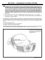
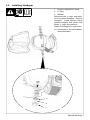
3-2. Installing Headgear
1 Distance Adjustment Knob
2O−Ring
3 Washer
Remove knobs, o−rings, and wash-
ers from helmet headgear. Remove
headgear. Install helmet cooling
system headgear and secure with
knobs, o−rings, and washers.
Retain old headgear for future use.
. See Section 4 for helmet adjust-
ment information.
1
3
2

OM-235 369 Page 8
3-3. Installing Head Shroud
After installing shroud,.
make sure there are no
gaps between shroud and
helmet edge.
1 Head Shroud
2 Magnetic Fastener
3 Elastic Loops
Position head shroud magnetic
fasteners on inside and outside
of helmet edge.
Stretch head shroud elastic
loops over helmet distance ad-
justment knobs.
. Remove shroud from hel-
met when using helmet with
the cooling system turned
off.
1
2
3
Notes
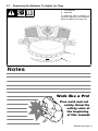
Work like a Pro!
Pros weld and cut
safely. Read the
safety rules at
the beginning
of this manual.

OM-235 369 Page 9
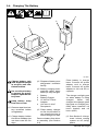
3-4. Charging The Battery
Charge battery only.
with supplied charger
in an open, well−ven-
tilated location.
Do not allow battery.
to get wet. Do not at-
tempt to open the bat-
tery case.
Keep battery away.
from fire or heat.
. Remove tape from bat-
tery terminals before
using battery.
. Charge battery before
first use or if battery has
not been used for five
days.
. Dispose of battery at a
designated collection
facility.
. Battery charging auto-
matically stops when
battery is fully charged.
1 Battery
2 Battery Charger
3 12 Volt AC Power
Adapter
4 120 Volt 15 A AC
Receptacle
. Place battery charger
on flat, level surface or
use supplied screw to
mount charger on wall.
Remove battery from blow-
er assembly (see Section
3-5).
Place battery in charger
base. Connect AC power
adapter cord to charger
base. Connect AC power
adapter to 120 volt AC re-
ceptacle.
The charger red light goes
on when battery is being
charged. When fully
charged, the charger green
light goes on. Charging nor-
mally takes between 3.5
hours (typical) and 4.5
hours (max.)
. See Section 3-10 to op-
erate helmet cooling
system on AC (utility)
power.
1
2
3
4
161-003

OM-235 369 Page 10
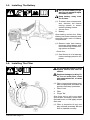
3-5. Installing The Battery
Do not allow battery to get.
wet. Do not attempt to open
the battery case.
Keep battery away from.
fire or heat.
. To better show components
and features, the helmet
cooling system is shown
without welding helmet.
1 Access Door
2 Battery
Open battery access door. Slide
battery into blower assembly until
terminals touch back of battery
compartment.
. Remove tape from battery
terminals. Install battery with
terminals facing helmet cool-
ing system as shown.
Close door.
. See Section 3-10 to operate
helmet cooling system on AC
power.
1
2
3-6. Installing The Filter
Do not use the helmet cooling.
system without the filter in-
stalled.
Replace damaged or dirty fil-.
ter. Do not wash filter, clean
with compressed air, or reuse
dirty filter.
. Filter is required for proper oper-
ation of equipment, but does not
provide respiratory protection.
1 Filter Cover
2 Filter
3 Finger Tab
Grip finger tab to pull cover away
from blower assembly. Install filter.
Reinstall cover so it fits tightly around
filter area.
. Filter is shaped to fit only one
way in blower assembly. Be sure
filter is installed correctly.
1 2 3

OM-235 369 Page 11
3-7. Removing Air Deflector To Adjust Air Flow
1 Air Deflector
2 Manifold
To adjust air flow in helmet, re-
move air deflector from manifold.
Save air deflector for later use.
1
2
Notes
Work like a Pro!
Pros weld and cut
safely. Read the
safety rules at
the beginning
of this manual.

OM-235 369 Page 12
3-8. Operating The Controls
1
23
Read and follow these.
instructions and the
safety labels carefully.
This product is in-
tended for use as a
cooling device only. It
is not a respiratory pro-
tective device and does
not protect the user
from airborne contami-
nants. Have an indus-
trial hygienist test the
air in your facility to de-
termine if respiratory
protection is required
to provide adequate
protection from con-
taminants in your envi-
ronment. With cooling
system-equipped hel-
met on your head and
cooling system operat-
ing, also test the air in-
side the helmet to de-
termine if respiratory
protection is required.
If you have questions
about the type of respi-
ratory protection
equipment required,
consult your safety di-
rector and an Industrial
Hygienist.
Do not restrict or alter.
helmet cooling system
air flow. Do not block
air holes (including up-
per and lower holes).
Be sure safety glasses,
hair, weld cap, and oth-
er objects do not block
air flow.
1 Power Button
To Start: Press Power but-
ton. Blower assembly starts
when button is released.
To Stop: Press Power button
again.
. Light pressure on Power
button turns unit off.
2 Battery Level Light
The Battery Level green light
goes on when blower as-
sembly is running and battery
is charged.
The Battery Level red light
flashes and blower assembly
pulses on and off when bat-
tery power is low.
The blower assembly stops
and Battery Level red light
stays on when battery is fully
discharged. See Section 3-4
for battery charging informa-
tion.
3 Aux Power Jack
Connect AC power adapter
cord to Aux Power jack to op-
erate helmet cooling system
on 120 volt AC power (see
Section 3-10). Reinstall cover
when not using Aux Power
jack.

OM-235 369 Page 13
3-9. Checking The Helmet Cooling System Before Use
Read and follow these in-.
structions and the safety
labels carefully. This
product is intended for
use as a cooling device
only. It is not a respirato-
ry protective device and
does not protect the user
from airborne contami-
nants. Have an industrial
hygienist test the air in
your facility to determine
if respiratory protection
is required to provide ad-
equate protection from
contaminants in your en-
vironment. With cooling
system-equipped helmet
on your head and cooling
system operating, also
test the air inside the hel-
met to determine if respi-
ratory protection is re-
quired. If you have ques-
tions about the type of
respiratory protection
equipment required,
consult your safety di-
rector and an Industrial
Hygienist.
Do not restrict or alter.
helmet cooling system
air flow. Do not block air
holes (including upper
and lower holes). Be sure
safety glasses, hair, weld
cap, and other objects do
not block air flow.
Before using the helmet cooling
system, check the following
items:
1 Filter
. Filter is required for proper
operation of equipment,
but does not provide respir-
atory protection.
Verify the filter is undamaged,
properly assembled, and se-
curely connected to the blower
assembly.
2 Flexible Tube
Be sure the tube is undamaged
and properly connected to the
manifold and blower assembly.
3 Battery
Verify the battery is fully
charged and secured in the bat-
tery compartment.
4 Air Flow
Turn on blower assembly and
test air flow.
5 Air Deflector
To adjust direction of air flow,
remove air deflector (see Sec-
tion 3-7).
6 Shroud (Not Shown)
Inspect the shroud and replace
if damaged. See Troubleshoot-
ing (Section 4-4) if air is not be-
ing supplied to front of helmet.
Put on helmet and adjust hel-
met so helmet fits snugly on
head. Verify shroud is properly
installed on helmet.
. See Section 4 (Miller hel-
met) or the welding helmet
Owner’s Manual for helmet
adjustment information.
3
2
5
1

OM-235 369 Page 14
3-10. Operating Helmet Cooling System On 120 Volt AC Power
1
1 Auxiliary Power Jack
To operate helmet cooling
system on AC (utility)
power, remove cord from
charger base and connect
to Aux Power jack on
blower assembly. Connect
other end of cord to 120 volt
15 A AC receptacle.
. The battery is not be-
ing charged when the
helmet cooling system
is connected to an AC
power supply.
. Battery can be re-
moved from helmet
cooling system when
using AC power.
. Obtain an additional
AC Power Adapter to
charge the battery
when the helmet cool-
ing system is operating
on AC power (see Sec-
tion 5 − Parts List).
Notes
Work like a Pro!
Pros weld and cut
safely. Read the
safety rules at
the beginning
of this manual.

OM-235 369 Page 15
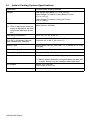
SECTION 4 − MAINTENANCE
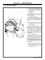
4-1. Adjusting Headgear
. There are four headgear adjust-
ments: headgear top, tightness,
angle adjustment, and distance
adjustment.
1 Headgear Top
Adjusts headgear for proper depth
on the head to ensure correct bal-
ance and stability.
2 Headgear Tightness
To adjust, push in the adjusting knob
located on the back of the headgear
and turn left or right to desired tight-
ness.
. If adjustment is limited, it may be
necessary to remove the com-
fort cushion.
3 Distance Adjustment
Adjusts the distance between the
face and the lens. To adjust, loosen
both outside tension knobs and
press inward to free from adjustment
slots. Move forward or back to de-
sired position and retighten. (Both
sides must be equally positioned for
proper vision.)
4 Angle Adjustment
Four pins on the right side of the
headband top provide adjustment
for the forward tilt of the helmet. To
adjust, loosen the right outside ten-
sion adjustment knob then lift on the
control arm tab and move it to the de-
sired position. Retighten tension ad-
justment knob.
. When using the back distance
adjustment positions, only the
back three angle adjustment
pins can be used.
804 118
1
2
3
4

OM-235 369 Page 16
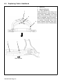
4-2. Replacing Fabric Headband
1 Manifold
2 Manifold Bracket
3 Fabric Headband
Slide manifold up and away from
manifold bracket. Push bracket to-
ward fabric headband and slide
bracket sideways to align slot with
tab on headgear. Remove bracket.
Remove fabric headband and clean
or replace. Reinstall fabric head-
band, manifold bracket, and mani-
fold in reverse order of disassembly.
1
2
2
3
3
Slide Bracket

OM-235 369 Page 17
4-3. Maintenance And Storage
Replace damaged or dirty filter. Do not wash filter, clean with compressed air, or reuse
dirty filter.
Never use solvents or abrasive cleaning solutions to clean the helmet cooling system.
Keep water and other fluids out of blower assembly.
Replace shroud after 50 washings. Shroud loses its fire retardant properties with re-
peated washing.
For best performance clean the equipment after each use. Use a soft cloth dampened with a mild soap
and water solution to wipe all external surfaces clean. Allow to air dry.
Product usage, workplace contamination levels, and other factors affect the life of the filter. Replace
filter if air flow is reduced due to a dirty filter (see Section 3-6).
Inspect flexible tube and replace if damaged or if inside of tube is extremely dirty.
If the helmet cooling system will not be used for an extended period, remove the filter and battery and
store in a clean, dry place free of solvent-based vapors them and at a temperature of −4° to 86° F (−20°
to 30° C). Charge battery to 50 percent capacity before storage.
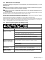
4-4. Helmet Cooling System Troubleshooting
Trouble Remedy
Blower assembly does not
supply air to helmet.
Press Power button.
Dead battery; recharge battery (see Section 3-5).
Remove tape from battery terminals (new battery only).
Verify battery contacts are clean and free of obstructions.
Remove blockage from blower assembly outlet and tube.
Blower assembly runs for
short time even though
battery is fully charged.
Be sure battery is properly connected to battery charger.
Replace battery.
Replace charger.
Battery Level red light is
on or flashing.
Charge or replace the battery. The blower assembly will operate
for about 15 minutes after the light starts flashing.
Blower assembly is
pulsing on and off.
Charge or replace the battery. The blower assembly will operate
for about 15 minutes after the light starts flashing.

OM-235 369 Page 18
Battery run time is too
short.
Replace battery.
Check filter and replace if necessary (see Section 3-6). A clogged
filter element reduces battery life.
Air supplied to helmet
smells and tastes unusual;
eyes and throat irritation.
Continue wearing the helmet cooling system and leave the area
immediately. Check contamination level of filter, and replace filter
if necessary.
Check flexible tube connection to blower assembly and manifold.
Have Safety Director and an Industrial Hygienist determine if you
are using the proper equipment for the work environment.
Blower assembly supplies
insufficient air to helmet.
Check filter and replace if necessary (see Section 3-6).
Check flexible tube connection to blower assembly and manifold.
Remove blockage from blower assembly outlet and/or tube.
Page is loading ...
Page is loading ...
Page is loading ...
Page is loading ...
-
 1
1
-
 2
2
-
 3
3
-
 4
4
-
 5
5
-
 6
6
-
 7
7
-
 8
8
-
 9
9
-
 10
10
-
 11
11
-
 12
12
-
 13
13
-
 14
14
-
 15
15
-
 16
16
-
 17
17
-
 18
18
-
 19
19
-
 20
20
-
 21
21
-
 22
22
-
 23
23
-
 24
24


Miller MPS-10T Owner's manual
- Category
- Welding System
- Type
- Owner's manual
- This manual is also suitable for
Ask a question and I''ll find the answer in the document
Finding information in a document is now easier with AI
Related papers
-
Miller MA000000 Owner's manual
-
-
-
Miller POWERED AIR PURIFYING-RESPIR. PAPR Owner's manual
-
-
-
-
-
-
Other documents
-
Lincoln Electric VIKING PAPR Operating instructions
-
3M Adflo™ Powered Air Purifying Respirator HE System Speedglas™ Welding Helmet 9100 FX-Air, 36-1101-20SW, 1 EA/CASE Operating instructions
-
-
3M 16961-Rev-7A User manual
-
ESAB Origo™ Air User manual
-
ESAB PAPR System User manual
-
Power Fist 8819922 Owner's manual
-
HobartWelders HELMET CREATOR AUTO-DARKENING Owner's manual
-
-
3M Inner Faceshield W-8160-10, 10 EA/Case Operating instructions