Page is loading ...

Operator’s Manual
VIKING PAPR 3350 WELDING HELMET
Register your machine:
www.lincolnelectric.com/register
Authorized Service and Distributor Locator:
www.lincolnelectric.com/locator
IM10151 | Issue D ate May-17
© Lincoln Global, Inc. All Rights Reserved.
Save for future reference
Date Purchased
K#: (ex: K3930-1)
Serial: (ex: U1060512345)
POWERED AIR-PURIFYING RESPIRATOR (PAPR)
WITH VIKING 3350 AUTO-DARKENING HELMET
WARNING: Users must read and understand the
user instructions prior to use. Use of this respirator
by untrained or unqualified people, or use that is not
in accordance with these user instructions, may
adversely affect respirator performance and may
be dangerous to your health. Keep this operator’s
manual for future reference.
PRODUCT NUMBER:
K3930-1

FUMES AND GASES can be dangerous to your health
.
• Fumes from the normal use of welding
products contain significant quantities of
potentially hazardous compounds. See
consumable product label/insert.
• Keep your head out of fumes.
• Use enough ventilation or local exhaust to keep fumes and
gases from your breathing zone and general area.
• An approved respirator should be used unless exposure
assessments are below applicable exposure limits.
• When welding with electrodes which may require additional
ventilation such as stainless or hard facing (see instructions on
container or Safety Data Sheet (SDS) or on lead or cadmium
plated steel and other metals or coatings which produce highly
toxic fumes, keep exposure as low as possible and within
applicable OSHA PEL and ACGIH TLV limits using local exhaust
or mechanical ventilation. In confined spaces or in some
circumstances, outdoors, a respirator may be required.
Additional precautions are also required when welding on
galvanized steel.
NIOSH approval
IMPORTANT: THIS RESPIRATOR IS INTENDED TO BE USED BY
TRAINED INDIVIDUALS IN ACCORDANCE WITH
ALL THE PROVISIONS OF AN ORGANIZED
RESPIRATORY PROTECTION PROGRAM WHICH
COMPLIES WITH THE REQUIREMENTS OF THE
OSHA STANDARD 29 CFR 1910.134 AVAILABLE
FROM THE US DEPARTMENT OF LABOR,
OCCUPATIONAL SAFETY AND HEALTH ADMINIS-
TRATION OR IN CANADA CONFORMANCE WITH
CSA Z94.4.
The Viking PAPR 3350 is approved in the USA by NIOSH for use
in environments where:
• Particulate concentrations are known and characterized.
• Particulate concentrations are not I mmediately Dangerous to
Life or Health (IDLH).
• Atmospheres are NOT oxygen deficient.
• Contaminant concentrations do not exceed the Maximum Use
Concentration (MUC) determined using the Assigned Protection
Factor (APF) for specific respirator system or the APF
mandated by specific government standards, whichever is
lower.
T
he Viking PAPR 3350 respirator components and filtration
media must be used only in configurations listed on the NIOSH
approval label. Refer to NIOSH approval label for list of approved
components.
This respirator is not capable of or approved for use in an area
which includes hazardous levels of gases . It is only effective to
filter out particulate contaminants.
ARC Rays can injure eyes and burn skin
• Before welding, always inspect helmet and
filter lens to be sure they are fitted
properly, in good condition and not
damaged.
• Check to see that the clear lens is clean and securely attached
to the helmet.
• Always wear safety glasses with side shields or goggles under
the welding helmet and protective clothing to protect your
skin from radiation, burns and spatter.
• Ensure that optical radiation from other welder’s arcs in the
immediate area does not enter in from behind the helmet
and auto-darkening filter.
• Stop welding immediately if the auto-darkening lens does not
darken when arc is struck. See instruction manual
for troubleshooting information.
• Do not weld in the overhead position while using this
helmet.
Note: Auto-darkening filters in Lincoln helmets are designed to
protect the user against harmful ultra-violet and infrared
rays both in the dark and light states. No matter what
shade the filter is set to, the UV/IR protection is always
present.
2
SAFETY
SAFETY WARNINGS – READ BEFORE USING
Refer to http: //www.lincolnelectric.com/safety for additional safety information.

THANK YOU FOR SELECTING
A QUALITY PRODUCT BY
LINCOLN ELEC TRIC.
PLEASE EXAMINE CARTON AND EQUIPMENT FOR
DAMAGE IMMEDIATELY
When this equipment is shipped, title passes to the purchaser
upon receipt by the carrier. Consequently, claims for material
damaged in shipment must be made by the purchaser against the
transportation company at the time the shipment is received.
SAFETY DEPENDS ON YOU
Lincoln arc welding and cutting equipment is designed and built
with safety in mind. However, your overall safety can be increased
by proper installation ... and thoughtful operation on your part.
DO NOT INSTALL, OPERATE OR REPAIR THIS EQUIPMENT
WITHOUT READING THIS MANUAL AND THE SAFETY
PRECAUTIONS CONTAINED THROUGHOUT. And, most importantly,
think before you act and be careful.
This statement appears where the information must be followed
exactly to avoid serious personal injury or loss of life.
This statement appears where the information must be followed
to avoid minor personal injury or damage to this equipment.
KEEP YOUR HEAD OUT OF THE FUMES.
DON’T get too close to the arc.
Use corrective lenses if necessary
to stay a reasonable distance
away from the arc.
READ and obey the Safety Data
Sheet (SDS) and the warning label
that appears on all containers of
welding materials.
USE ENOUGH VENTILATION or
exhaust at the arc, or both, to
keep the fumes and gases from
your breathing zone and the general area.
IN A LARGE ROOM OR OUTDOORS, natural ventilation may be
adequate if you keep your head out of the fumes (See below).
USE NATURAL DRAFTS or fans to keep the fumes away
from your face.
If you de velop unusual symptoms, see your supervisor.
Perhaps the welding atmosphere and ventilation system
should be checked.
WEAR CORRECT EYE, EAR &
BODY PROTECTION
PROTECT your eyes and face with welding helmet
properly fitted and with proper grade of filter plate
(See ANSI Z49.1).
PROTECT your body from welding spatter and arc
flash with protective clothing including woolen
clothing, flame-proof apron and gloves, leather
leggings, and high boots.
PROTECT others from splatter, flash, and glare
with protective screens or barriers.
IN SOME AREAS, protection from noise may be appropriate.
BE SURE protective equipment is in good condition.
Also, wear safety glasses in work area
AT ALL TIMES.
SPECIAL SITUATIONS
DO NOT WELD OR CUT containers or materials which previously
had been in contact with hazardous substances unless they are
properly cleaned. This is extremely dangerous.
DO NOT WELD OR CUT painted or plated parts unless special
precautions with ventilation have been taken. They can release
highly toxic fumes or gases.
Additional precautionary measures
PROTECT compressed gas cylinders from excessive heat,
mechanical shocks, and arcs; fasten cylinders so they cannot fall.
BE SURE cylinders are never grounded or part of an
electrical circuit.
REMOVE all potential fire hazards from welding area.
ALWAYS HAVE FIRE FIGHTING EQUIPMENT READY FOR
IMMEDIATE USE AND KNOW HOW TO USE IT.
WARNING
CAUTION
Safety 01 of 04 - 5/16/2018

SECTION A:
WARNINGS
CALIFORNIA PROPOSITION 65 WARNINGS
WARNING: Breathing diesel engine exhaust
exposes you to chemicals known to the State
of California to cause cancer and birth defects,
or other reproductive harm.
• Always start and operate the engine in a
well-ventilated area.
• If in an exposed area, vent the exhaust to the outside.
• Do not modify or tamper with the exhaust system.
• Do not idle the engine except as necessary.
For more information go to
www.P65 warnings.ca.gov/diesel
WARNING: This product, when used for welding or
cutting, produces fumes or gases which contain
chemicals known to the State of California to cause
birth defects and, in some cases, cancer. (California
Health & Safety Code § 25249.5 et seq.)
WARNING: Cancer and Reproductive Harm
www.P65warnings.ca.gov
ARC WELDING CAN BE HAZARDOUS. PROTECT
YOURSELF AND OTHERS FROM POSSIBLE SERIOUS
INJURY OR DEATH. KEEP CHILDREN AWAY.
PACEMAKER WEARERS SHOULD CONSULT WITH
THEIR DOCTOR BEFORE OPERATING.
Read and understand the following safety highlights. For
additional safety information, it is strongly recommended
that you purchase a copy of “Safety in Welding & Cutting -
ANSI Standard Z49.1” from the American Welding Society,
P.O. Box 351040, Miami, Florida 33135 or CSA Standard
W117.2-1974. A Free copy of “Arc Welding Safety” booklet
E205 is available from the Lincoln Electric Company,
22801 St. Clair Avenue, Cleveland, Ohio 44117-1199.
BE SURE THAT ALL INSTALLATION, OPERATION,
MAINTENANCE AND REPAIR PROCEDURES ARE
PERFORMED ONLY BY QUALIFIED INDIVIDUALS.
FOR ENGINE POWERED
EQUIPMENT.
1.a. Turn the engine off before troubleshooting
and maintenance work unless the
maintenance work requires it to be running.
1.b. Operate engines in open, well-ventilated areas or vent the engine
exhaust fumes outdoors.
1.c. Do not add the fuel near an open flame welding
arc or when the engine is running. Stop the
engine and allow it to cool before refueling to
prevent spilled fuel from vaporizing on contact
with hot engine parts and igniting. Do not spill fuel when filling
tank. If fuel is spilled, wipe it up and do not start engine until
fumes have been eliminated.
1.d. Keep all equipment safety guards, covers
and devices in position and in good repair.
Keep hands, hair, clothing and tools away
from V-belts, gears, fans and all other
moving parts when starting, operating or
repairing equipment.
1.e. In some cases it may be necessary to remove safety guards to
perform required maintenance. Remove guards only when
necessary and replace them when the maintenance requiring
their removal is complete. Always use the greatest care when
working near moving parts.
1.f. Do not put your hands near the engine fan. Do not attempt to
override the governor or idler by pushing on the throttle control
rods while the engine is running.
1.g. To prevent accidentally starting gasoline engines while turning
the engine or welding generator during maintenance work,
disconnect the spark plug wires, distributor cap or magneto wire
as appropriate.
1.h. To avoid scalding, do not remove the radiator
pressure cap when the engine is
hot.
ELECTRIC AND
MAGNETIC FIELDS MAY
BE DANGEROUS
2.a. Electric current flowing through any conductor
causes localized Electric and Magnetic Fields (EMF).
Welding current creates EMF fields around welding cables
and welding machines
2.b. EMF fields may interfere with some pacemakers, and
welders having a pacemaker should consult their physician
before welding.
2.c. Exposure to EMF fields in welding may have other health effects
which are now not known.
2.d. All welders should use the following procedures in order to
minimize exposure to EMF fields from the welding circuit:
2.d.1. Route the electrode and work cables together - Secure
them with tape when possible.
2.d.2. Never coil the electrode lead around your body.
2.d.3. Do not place your body between the electrode and work
cables. If the electrode cable is on your right side, the
work cable should also be on your right side.
2.d.4. Connect the work cable to the workpiece as close as pos-
sible to the area being welded.
2.d.5. Do not work next to welding power source.
SAFETY
Safety 02 of 04 - 5/16/2018

ELECTRIC SHOCK
CAN KILL.
3.a. The electrode and work (or ground) circuits are
electrically “hot” when the welder is on. Do
not touch these “hot” parts with your bare skin or wet clothing.
Wear dry, hole-free gloves to insulate hands.
3.b. Insulate yourself from work and ground using dry insulation.
Make certain the insulation is large enough to cover your full area
of physical contact with work and ground.
In addition to the normal safety precautions, if
welding must be performed under electrically
hazardous conditions (in damp locations or while
wearing wet clothing; on metal structures such as
floors, gratings or scaffolds; when in cramped
positions such as sitting, kneeling or lying, if there
is a high risk of unavoidable or accidental contact
with the workpiece or ground) use the following
equipment:
• Semiautomatic DC Constant Voltage (Wire) Welder.
• DC Manual (Stick) Welder.
• AC Welder with Reduced Voltage Control.
3.c. In semiautomatic or automatic wire welding, the electrode,
electrode reel, welding head, nozzle or semiautomatic welding
gun are also electrically “hot”.
3.d. Always be sure the work cable makes a good electrical
connection with the metal being welded. The connection should
be as close as possible to the area being welded.
3.e. Ground the work or metal to be welded to a good electrical (earth)
ground.
3.f. Maintain the electrode holder, work clamp, welding cable and
welding machine in good, safe operating condition. Replace
damaged insulation.
3.g. Never dip the electrode in water for cooling.
3.h. Never simultaneously touch electrically “hot” parts of electrode
holders connected to two welders because voltage
between the
two can be the total of the open circuit voltage of both
welders.
3.i. When working above floor level, use a safety belt to protect
yourself from a fall should you get a shock.
3.j. Also see It ems 6.c. and 8.
ARC RAYS CAN BURN.
4.a. Use a shield with the proper filter and cover plates to protect your
eyes from sparks and the rays of the arc when welding or
observing open arc welding. Headshield and filter lens should
conform to ANSI Z87. I standards.
4.b. Use suitable clothing made from durable flame-resistant material
to protect your skin and that of your helpers from the arc rays.
4.c. Protect other nearby personnel with suitable, non-flammable
screening and/or warn them not to watch the arc nor expose
themselves to the arc rays or to hot spatter or metal.
FUMES AND GASES
CAN BE DANGEROUS.
5.a. Welding may produce fumes and gases
hazardous to health. Avoid breathing these
fumes and gases. When welding, keep your head out of the fume.
Use enough ventilation and/or exhaust at the arc to keep fumes
and gases away from the breathing zone. When welding
hardfacing (see instructions on container or SDS)
or on lead or cadmium plated steel and other
metals or coatings which produce highly toxic
fumes, keep exposure as low as possible and
within applicable OSHA PEL and ACGIH TLV limits
using local exhaust or mechanical ventilation
unless exposure assessments indicate otherwise.
In confined spaces or in some circumstances,
outdoors, a respirator may also be required.
Additional precautions are also required when
welding
on galvanized steel.
5. b. The operation of welding fume control equipment is affected by
various factors including proper use and positioning of the
equipment, maintenance of the equipment and the specific
welding procedure and application involved. Worker exposure
level should be checked upon installation and periodically
thereafter to be certain it is within applicable OSHA PEL and
ACGIH TLV limits.
5.c. Do not weld in locations near chlorinated hydrocarbon vapors
coming from degreasing, cleaning or spraying operations. The
heat and rays of the arc can react with solvent vapors to form
phosgene, a highly toxic gas, and other irritating products.
5.d. Shielding gases used for arc welding can displace air and
cause
injury or death. Always use enough ventilation, especially in
confined areas, to insure breathing air is safe.
5.e. Read and understand the manufacturer’s instructions for this
equipment and the consumables to be used, including the
Safety Data Sheet (SDS) and follow your employer’s safety
practices. SDS forms are available from your welding
distributor or from the manufacturer.
5.f. Also see item 1.b.
SAFETY
Safety 03 of 04 - 5/16/2018

WELDING AND CUTTING
SPARKS CAN CAUSE
FIRE OR EXPLOSION.
6.a. Remove fire hazards from the welding area. If
this is not possible, cover them to prevent the welding sparks
from starting a fire. Remember that welding sparks and hot
materials from welding can easily go through small cracks and
openings to adjacent areas. Avoid welding near hydraulic lines.
Have a fire extinguisher readily available.
6.b. Where compressed gases are to be used at the job site, special
precautions should be used to prevent hazardous situations.
Refer to “Safety in Welding and Cutting” (ANSI Standard Z49.1)
and the operating information for the equipment being used.
6.c. When not welding, make certain no part of the electrode circuit is
touching the work or ground. Accidental contact can cause
overheating and create a fire hazard.
6.d. Do not heat, cut or weld tanks, drums or containers until the
proper steps have been taken to insure that such procedures
will not cause flammable or toxic vapors from substances inside.
They can cause an explosion even though they have been
“cleaned”. For information, purchase “Recommended Safe
Practices for the Preparation for Welding and Cutting of
Containers and Piping That Have Held Hazardous Substances”,
AWS F4.1 from the American Welding Society
(see address above).
6.e. Vent hollow castings or containers before heating, cutting or
welding. They may explode.
6.f. Sparks and spatter are thrown from the welding arc. Wear oil free
protective garments such as leather gloves, heavy shirt, cuffless
trousers, high shoes and a cap over your hair. Wear ear plugs
when welding out of position or in confined places. Always wear
safety glasses with side shields when in a welding area.
6.g. Connect the work cable to the work as close to the welding area
as practical. Work cables connected to the building framework or
other locations away from the welding area increase the
possibility of the welding current passing through lifting chains,
crane cables or other alternate circuits. This can create fire
hazards or overheat lifting chains or cables until they fail.
6.h. Also see item 1.c.
6.I. Read and follow NFPA 51B “Standard for Fire Prevention During
Welding, Cutting and Other Hot Work”, available from NFPA, 1
Batterymarch Park, PO box 9101, Quincy, MA 022690-9101.
6.j. Do not use a welding power source for pipe thawing.
CYLINDER MAY EXPLODE IF
DAMAGED.
7.a. Use only compressed gas cylinders containing
the correct shielding gas for the process used
and properly operating regulators designed for
the gas and pressure used. All hoses, fittings,
etc. should be suitable for the application and
maintained in good condition.
7.b. Always keep cylinders in an upright position securely chained to
an undercarriage or fixed support.
7.c. Cylinders should be located:
• Away from areas where they may be struck or subjected
to physical damage.
• A safe distance from arc welding or cutting operations
and any other source of heat, sparks, or flame.
7.d. Never allow the electrode, electrode holder or any other
electrically “hot” parts to touch a cylinder.
7.e. Keep your head and face away from the cylinder valve outlet
when opening the cylinder valve.
7.f. Valve protection caps should always be in place and hand tight
except when the cylinder is in use or connected for use.
7.g. Read and follow the instructions on compressed gas cylinders,
associated equipment, and CGA publication P-l, “Precautions for
Safe Handling of Compressed Gases in Cylinders,” available from
the Compressed Gas Association, 14501 George Carter Way
Chantilly, VA 20151.
FOR ELECTRICALLY
POWERED EQUIPMENT.
8.a. Turn off input power using the disconnect
switch at the fuse box before working on
the equipment.
8.b. Install equipment in accordance with the U.S. National Electrical
Code, all local codes and the manufacturer’s recommendations.
8.c. Ground the equipment in accordance with the U.S. National
Electrical Code and the manufacturer’s recommendations.
Refer to
http://www.lincolnelectric.com/safety
for additional safety information.
SAFETY
Safety 04 of 04 - 5/16/2018

7
TABLE OF CONTENTS
P
a
g
e
SA
F
E
T
Y
W
A
R
N
IN
G
S
–
R
E
A
D
B
E
F
O
R
E
U
SE
.
.
.
.
.
.
.
.
.
.
.
.
.
.
.
.
.
.
.
.
.
.
.
.
.
.
.
.
.
.
.
.
.
.
.
.
.
.
.
.
.
.
.
.
.
.
.
.
.
.
.
.
.
.
.
.
.
.
.
.
.
.
.
.
.
.
.
.
.
.
.
.
.
.
.
.
.
.
.
.
.
.
.
.
.
.
.
.
.
.
.
.
.
2
A
r
c
W
el
d
i
n
g
S
afety
.
.
.
.
.
.
.
.
.
.
.
.
.
.
.
.
.
.
.
.
.
.
.
.
.
.
.
.
.
.
.
.
.
.
.
.
.
.
.
.
.
.
.
.
.
.
.
.
.
.
.
.
.
.
.
.
.
.
.
.
.
.
.
.
.
.
.
.
.
.
.
.
.
.
.
.
.
.
.
.
.
.
.
.
.
.
.
.
.
.
.
.
.
.
.
.
.
.
.
.
.
.
.
.
.
.
.
.
.
.
.
.
.
.
.
.
.
.
.
.
.
.
2
N
I
O
S
H
ap
p
r
ov
al
.
.
.
.
.
.
.
.
.
.
.
.
.
.
.
.
.
.
.
.
.
.
.
.
.
.
.
.
.
.
.
.
.
.
.
.
.
.
.
.
.
.
.
.
.
.
.
.
.
.
.
.
.
.
.
.
.
.
.
.
.
.
.
.
.
.
.
.
.
.
.
.
.
.
.
.
.
.
.
.
.
.
.
.
.
.
.
.
.
.
.
.
.
.
.
.
.
.
.
.
.
.
.
.
.
.
.
.
.
.
.
.
.
.
.
.
.
.
.
.
.
.
.
.
.
.
.
2
S
tan
d
ar
d
S
afety
W
ar
n
i
n
g
s
for
P
ow
er
S
ou
r
ces
an
d
W
i
r
e
Feed
er
s
.
.
.
.
.
.
.
.
.
.
.
.
.
.
.
.
.
.
.
.
.
.
.
.
.
.
.
.
.
.
.
.
.
.
.
.
.
.
.
.
.
.
.
.
3
th
r
u
6
T
ab
l
e
of
Con
ten
ts
.
.
.
.
.
.
.
.
.
.
.
.
.
.
.
.
.
.
.
.
.
.
.
.
.
.
.
.
.
.
.
.
.
.
.
.
.
.
.
.
.
.
.
.
.
.
.
.
.
.
.
.
.
.
.
.
.
.
.
.
.
.
.
.
.
.
.
.
.
.
.
.
.
.
.
.
.
.
.
.
.
.
.
.
.
.
.
.
.
.
.
.
.
.
.
.
.
.
.
.
.
.
.
.
.
.
.
.
.
.
.
.
.
.
.
.
.
.
.
.
.
.
.
.
.
.
.
.
.
.
.
.7
N
i
os
h
Cau
ti
on
s
an
d
Li
m
i
tati
on
s
.
.
.
.
.
.
.
.
.
.
.
.
.
.
.
.
.
.
.
.
.
.
.
.
.
.
.
.
.
.
.
.
.
.
.
.
.
.
.
.
.
.
.
.
.
.
.
.
.
.
.
.
.
.
.
.
.
.
.
.
.
.
.
.
.
.
.
.
.
.
.
.
.
.
.
.
.
.
.
.
.
.
.
.
.
.
.
.
. 8
Po
we
r
e
d
A
i
r
-
Pu
r
i
f
yi
n
g
R
e
sp
i
r
a
t
o
r
Se
c
t
i
o
n
.
.
.
.
.
.
.
.
.
.
.
.
.
.
.
.
.
.
.
.
.
.
.
.
.
.
.
.
.
.
.
.
.
.
.
.
.
.
.
.
.
.
.
.
.
.
.
.
.
.
.
.
.
.
.
.
.
.
.
.
.
.
.
.
.
.
.
.
.
.
.
.
.
.
.
.
.
. 8
Res
p
i
r
ator
S
p
eci
fi
cati
on
s
.
.
.
.
.
.
.
.
.
.
.
.
.
.
.
.
.
.
.
.
.
.
.
.
.
.
.
.
.
.
.
.
.
.
.
.
.
.
.
.
.
.
.
.
.
.
.
.
.
.
.
.
.
.
.
.
.
.
.
.
.
.
.
.
.
.
.
.
.
.
.
.
.
.
.
.
.
.
.
.
.
.
.
.
.
.
.
.
.
.
.
.
.
.
.
.
.
.
.
.
.
.
.
.
.
.
.
.
.
.
.
.
.
8
Batter
y
O
p
er
ati
on
s
.
.
.
.
.
.
.
.
.
.
.
.
.
.
.
.
.
.
.
.
.
.
.
.
.
.
.
.
.
.
.
.
.
.
.
.
.
.
.
.
.
.
.
.
.
.
.
.
.
.
.
.
.
.
.
.
.
.
.
.
.
.
.
.
.
.
.
.
.
.
.
.
.
.
.
.
.
.
.
.
.
.
.
.
.
.
.
.
.
.
.
.
.
.
.
.
.
.
.
.
.
.
.
.
.
.
.
.
.
.
.
.
.
.
.
.
.
.
.
.
.
.
.
9
I
n
s
tal
l
i
n
g
Batter
y
P
ack
.
.
.
.
.
.
.
.
.
.
.
.
.
.
.
.
.
.
.
.
.
.
.
.
.
.
.
.
.
.
.
.
.
.
.
.
.
.
.
.
.
.
.
.
.
.
.
.
.
.
.
.
.
.
.
.
.
.
.
.
.
.
.
.
.
.
.
.
.
.
.
.
.
.
.
.
.
.
.
.
.
.
.
.
.
.
.
.
.
.
.
.
.
.
.
.
.
.
.
.
.
.
.
.
.
.
.
.
.
.
.
.
.
.
.
1
0
Fi
l
ter
I
n
s
tal
l
ati
on
.
.
.
.
.
.
.
.
.
.
.
.
.
.
.
.
.
.
.
.
.
.
.
.
.
.
.
.
.
.
.
.
.
.
.
.
.
.
.
.
.
.
.
.
.
.
.
.
.
.
.
.
.
.
.
.
.
.
.
.
.
.
.
.
.
.
.
.
.
.
.
.
.
.
.
.
.
.
.
.
.
.
.
.
.
.
.
.
.
.
.
.
.
.
.
.
.
.
.
.
.
.
.
.
.
.
.
.
.
.
.
.
.
.
.
.
.
.
.
.
.
.
.
.
1
1
Br
eath
i
n
g
T
u
b
e
I
n
s
tal
l
ati
on
.
.
.
.
.
.
.
.
.
.
.
.
.
.
.
.
.
.
.
.
.
.
.
.
.
.
.
.
.
.
.
.
.
.
.
.
.
.
.
.
.
.
.
.
.
.
.
.
.
.
.
.
.
.
.
.
.
.
.
.
.
.
.
.
.
.
.
.
.
.
.
.
.
.
.
.
.
.
.
.
.
.
.
.
.
.
.
.
.
.
.
.
.
.
.
.
.
.
.
.
.
.
.
.
.
.
.
.
1
2
S
h
ou
l
d
er
S
tr
ap
I
n
s
tal
l
ati
on
s
.
.
.
.
.
.
.
.
.
.
.
.
.
.
.
.
.
.
.
.
.
.
.
.
.
.
.
.
.
.
.
.
.
.
.
.
.
.
.
.
.
.
.
.
.
.
.
.
.
.
.
.
.
.
.
.
.
.
.
.
.
.
.
.
.
.
.
.
.
.
.
.
.
.
.
.
.
.
.
.
.
.
.
.
.
.
.
.
.
.
.
.
.
.
.
.
.
.
.
.
.
.
.
.
.
.
.
1
3
Res
p
i
r
ator
Con
tr
ol
s
.
.
.
.
.
.
.
.
.
.
.
.
.
.
.
.
.
.
.
.
.
.
.
.
.
.
.
.
.
.
.
.
.
.
.
.
.
.
.
.
.
.
.
.
.
.
.
.
.
.
.
.
.
.
.
.
.
.
.
.
.
.
.
.
.
.
.
.
.
.
.
.
.
.
.
.
.
.
.
.
.
.
.
.
.
.
.
.
.
.
.
.
.
.
.
.
.
.
.
.
.
.
.
.
.
.
.
.
.
.
.
.
.
.
.
.
.
.
.
.
1
4
A
i
r
Fl
ow
A
l
ar
m
O
p
er
ati
on
.
.
.
.
.
.
.
.
.
.
.
.
.
.
.
.
.
.
.
.
.
.
.
.
.
.
.
.
.
.
.
.
.
.
.
.
.
.
.
.
.
.
.
.
.
.
.
.
.
.
.
.
.
.
.
.
.
.
.
.
.
.
.
.
.
.
.
.
.
.
.
.
.
.
.
.
.
.
.
.
.
.
.
.
.
.
.
.
.
.
.
.
.
.
.
.
.
.
.
.
.
.
.
.
.
.
.
.
.
.
.
1
5
A
i
r
Fl
ow
Con
tr
ol
.
.
.
.
.
.
.
.
.
.
.
.
.
.
.
.
.
.
.
.
.
.
.
.
.
.
.
.
.
.
.
.
.
.
.
.
.
.
.
.
.
.
.
.
.
.
.
.
.
.
.
.
.
.
.
.
.
.
.
.
.
.
.
.
.
.
.
.
.
.
.
.
.
.
.
.
.
.
.
.
.
.
.
.
.
.
.
.
.
.
.
.
.
.
.
.
.
.
.
.
.
.
.
.
.
.
.
.
.
.
.
.
.
.
.
.
.
.
.
.
.
.
.
.
.
1
6
P
r
ep
ar
i
n
g
For
Us
e
.
.
.
.
.
.
.
.
.
.
.
.
.
.
.
.
.
.
.
.
.
.
.
.
.
.
.
.
.
.
.
.
.
.
.
.
.
.
.
.
.
.
.
.
.
.
.
.
.
.
.
.
.
.
.
.
.
.
.
.
.
.
.
.
.
.
.
.
.
.
.
.
.
.
.
.
.
.
.
.
.
.
.
.
.
.
.
.
.
.
.
.
.
.
.
.
.
.
.
.
.
.
.
.
.
.
.
.
.
.
.
.
.
.
.
.
.
.
.
.
.
.
1
7
Donning
Proced
ure
for
Res
p
irator
.
.
.
.
.
.
.
.
.
.
.
.
.
.
.
.
.
.
.
.
.
.
.
.
.
.
.
.
.
.
.
.
.
.
.
.
.
.
.
.
.
.
.
.
.
.
.
.
.
.
.
.
.
.
.
.
.
.
.
.
.
.
.
.
.
.
.
.
.
.
.
.
.
.
.
.
.
.
.
.
.
.
.
.
.
.
.
.
.
.
.
.
.
.
.
.
.
.18
Res
p
irator
Main
tenance
and
S
torage.
.
.
.
.
.
.
.
.
.
.
.
.
.
.
.
.
.
.
.
.
.
.
.
.
.
.
.
.
.
.
.
.
.
.
.
.
.
.
.
.
.
.
.
.
.
.
.
.
.
.
.
.
.
.
.
.
.
.
.
.
.
.
.
.
.
.
.
.
.
.
.
.
.
.
.
.
.
.
.
.
.
.
.
.
.
.
.
.
.
.
.
.
18
Trou
b
le
S
h
ooting
G
uid
e
For
Res
p
irator
.
.
.
.
.
.
.
.
.
.
.
.
.
.
.
.
.
.
.
.
.
.
.
.
.
.
.
.
.
.
.
.
.
.
.
.
.
.
.
.
.
.
.
.
.
.
.
.
.
.
.
.
.
.
.
.
.
.
.
.
.
.
.
.
.
.
.
.
.
.
.
.
.
.
.
.
.
.
.
.
.
.
.
.
.
.
.
.
.
.
.
19
Au
to-
Dar
k
en
i
n
g
He
l
m
e
t
Se
c
ti
on
.
.
.
.
.
.
.
.
.
.
.
.
.
.
.
.
.
.
.
.
.
.
.
.
.
.
.
.
.
.
.
.
.
.
.
.
.
.
.
.
.
.
.
.
.
.
.
.
.
.
.
.
.
.
.
.
.
.
.
.
.
.
.
.
.
.
.
.
.
.
.
.
.
.
.
.
.
.
.
.
.
.
.
.
.
.
.
.
.
.20
H
elm
et/
Lens
Inform
ation.
.
.
.
.
.
.
.
.
.
.
.
.
.
.
.
.
.
.
.
.
.
.
.
.
.
.
.
.
.
.
.
.
.
.
.
.
.
.
.
.
.
.
.
.
.
.
.
.
.
.
.
.
.
.
.
.
.
.
.
.
.
.
.
.
.
.
.
.
.
.
.
.
.
.
.
.
.
.
.
.
.
.
.
.
.
.
.
.
.
.
.
.
.
.
.
.
.
.
.
.
.
.
.
.
.
.
.
.
.
.
20
A
u
to-Darkenin
g
Len
s
S
p
ecification
s
.
.
.
.
.
.
.
.
.
.
.
.
.
.
.
.
.
.
.
.
.
.
.
.
.
.
.
.
.
.
.
.
.
.
.
.
.
.
.
.
.
.
.
.
.
.
.
.
.
.
.
.
.
.
.
.
.
.
.
.
.
.
.
.
.
.
.
.
.
.
.
.
.
.
.
.
.
.
.
.
.
.
.
.
.
.
.
.
.
.
.
.
.
.
21
W
eld
ing
H
elm
et
Op
eratin
g
In
s
truction
s
.
.
.
.
.
.
.
.
.
.
.
.
.
.
.
.
.
.
.
.
.
.
.
.
.
.
.
.
.
.
.
.
.
.
.
.
.
.
.
.
.
.
.
.
.
.
.
.
.
.
.
.
.
.
.
.
.
.
.
.
.
.
.
.
.
.
.
.
.
.
.
.
.
.
.
.
.
.
.
.
.
.
.
.
.
.
.
.
.
.
22
Cartrid
ge
Operation
/
Featu
res
.
.
.
.
.
.
.
.
.
.
.
.
.
.
.
.
.
.
.
.
.
.
.
.
.
.
.
.
.
.
.
.
.
.
.
.
.
.
.
.
.
.
.
.
.
.
.
.
.
.
.
.
.
.
.
.
.
.
.
.
.
.
.
.
.
.
.
.
.
.
.
.
.
.
.
.
.
.
.
.
.
.
.
.
.
.
.
.
.
.
.
.
.
.
.
.
.
.
.
.
.
.
.
.
.
23
S
had
e
G
uid
e
S
ettin
g
s
.
.
.
.
.
.
.
.
.
.
.
.
.
.
.
.
.
.
.
.
.
.
.
.
.
.
.
.
.
.
.
.
.
.
.
.
.
.
.
.
.
.
.
.
.
.
.
.
.
.
.
.
.
.
.
.
.
.
.
.
.
.
.
.
.
.
.
.
.
.
.
.
.
.
.
.
.
.
.
.
.
.
.
.
.
.
.
.
.
.
.
.
.
.
.
.
.
.
.
.
.
.
.
.
.
.
.
.
.
.
.
.
.
.
.
. 24
Cartridg
e
an
d
Len
s
Rep
lacem
en
t.
.
.
.
.
.
.
.
.
.
.
.
.
.
.
.
.
.
.
.
.
.
.
.
.
.
.
.
.
.
.
.
.
.
.
.
.
.
.
.
.
.
.
.
.
.
.
.
.
.
.
.
.
.
.
.
.
.
.
.
.
.
.
.
.
.
.
.
.
.
.
.
.
.
.
.
.
.
.
.
.
.
.
.
.
.
.
.
.
.
.
.
.
.
.
.
.
.
.25
Trouble
S
hooting
G
uide
for
H
elm
et
Cartridge
.
.
.
.
.
.
.
.
.
.
.
.
.
.
.
.
.
.
.
.
.
.
.
.
.
.
.
.
.
.
.
.
.
.
.
.
.
.
.
.
.
.
.
.
.
.
.
.
.
.
.
.
.
.
.
.
.
.
.
.
.
.
.
.
.
.
.
.
.
.
.
.
.
.
.
.
.
.
.
.
.
26
H
elm
et
W
arranty
Inform
ation
.
.
.
.
.
.
.
.
.
.
.
.
.
.
.
.
.
.
.
.
.
.
.
.
.
.
.
.
.
.
.
.
.
.
.
.
.
.
.
.
.
.
.
.
.
.
.
.
.
.
.
.
.
.
.
.
.
.
.
.
.
.
.
.
.
.
.
.
.
.
.
.
.
.
.
.
.
.
.
.
.
.
.
.
.
.
.
.
.
.
.
.
.
.
.
.
.
.
.
.
.
.
.
.
. 27
H
elm
et
Replacem
ent
Parts
.
.
.
.
.
.
.
.
.
.
.
.
.
.
.
.
.
.
.
.
.
.
.
.
.
.
.
.
.
.
.
.
.
.
.
.
.
.
.
.
.
.
.
.
.
.
.
.
.
.
.
.
.
.
.
.
.
.
.
.
.
.
.
.
.
.
.
.
.
.
.
.
.
.
.
.
.
.
.
.
.
.
.
.
.
.
.
.
.
.
.
.
.
.
.
.
.
.
.
.
.
.
.
.
.
.
.
. 27
Optional
A
cces
s
ories
.
.
.
.
.
.
.
.
.
.
.
.
.
.
.
.
.
.
.
.
.
.
.
.
.
.
.
.
.
.
.
.
.
.
.
.
.
.
.
.
.
.
.
.
.
.
.
.
.
.
.
.
.
.
.
.
.
.
.
.
.
.
.
.
.
.
.
.
.
.
.
.
.
.
.
.
.
.
.
.
.
.
.
.
.
.
.
.
.
.
.
.
.
.
.
.
.
.
.
.
.
.
.
.
.
.
.
.
.
.
.
.
.
.
.
.
. 27
W
ar
r
an
ty
In
for
m
ati
on
.
.
.
.
.
.
.
.
.
.
.
.
.
.
.
.
.
.
.
.
.
.
.
.
.
.
.
.
.
.
.
.
.
.
.
.
.
.
.
.
.
.
.
.
.
.
.
.
.
.
.
.
.
.
.
.
.
.
.
.
.
.
.
.
.
.
.
.
.
.
.
.
.
.
.
.
.
.
.
.
.
.
.
.
.
.
.
.
.
.
.
.
.
.
.
.
.
.
.
.
.
.
.
.
.
.
.
.
.
.
.
.
.
.
.
.
.
.
.
.
. 28
Par
ts
Pag
es.
.
.
.
.
.
.
.
.
.
.
.
.
.
.
.
.
.
.
.
.
.
.
.
.
.
.
.
.
.
.
.
.
.
.
.
.
.
.
.
.
.
.
.
.
.
.
.
.
.
.
.
.
.
.
.
.
.
.
.
.
.
.
.
.
.
.
.
.
.
.
.
.
.
.
.
.
.
.
.
.
.
.
.
.
.
.
.
.
.
.
.
.
.
.
.
.
.
.
.
.
.
.
.
.
.
.
.
.
.
.
.
.
.
.
.
.
.
.
.
.
.
.
.
.
.
.
.
.
.
. 28,
29

8
V
IKING PAPR 3350 WELDING HELMET
NIOSH CAUTIONS AND LIMITATIONS
A – Not for use in atmospheres containing less than 19.5%
oxygen.
B – Not for use in atmospheres immediately dangerous to life or
h
ealth.
C
– Do not exceed maximum use concentrations established by
regulatory standards.
F – Do not use powered air-purifying respirators if airflow is less
than four cfm (115 lpm) for tight fitting
facepieces or six cfm (170 lpm) for hoods and/or helmets.
I – Contains electrical parts that may cause an ignition in
flammable or explosive atmospheres.
J - Failure to properly use and maintain this product could result
in injury or death.
L – Follow the manufacturer’s User’s Instructions for changing
cartridges, canister and/or filters.
M – All approved respirators shall be selected, fitted, used, and
maintained in accordance with MSHA, OSHA, and other
applicable regulations.
N – Never substitute, modify, add, or omit parts. Use only exact
r
eplacement parts in the configuration as specified by the
manufacturer.
O - Refer to User’s Instructions, and/or maintenance manuals for
information on use and maintenance of these respirators.
P - NIOSH does not evaluate respirators for use as surgical
masks.
POWERED AIR-PURIFYING RESPIRATOR SECTION
RESPIRATOR SPECIFICATIONS
Size of Blower Assembly 8” W x 7.5” T x 3” D (203 x 191 x 76 mm)
Weight of Blower (including battery, belt, and filters) 47 oz. (1338 g)
Weight of Helmet Assembly 32 oz. (899 g)
Air Flow Low Speed: 170+ lpm (6+ cfm)
High Speed: 210+ lpm (7.4+ cfm)
Operating Temperature 23°F to 131°F (-5°C to 55°C)
Storage Temperature 23°F to 131°F (-5°C to 55°C)
Battery Type Lithium Ion (Rechargeable)
Battery Charge Time About three hours
Battery Life Approximately 500 charges
Belt Size
(3)
29 to 52 in. (736 to 1321 mm)
Helmet Compliance ANSI Z87.1-2010, CSA Z94.3, CE EN 379
Respirator Approval
(1)
NIOSH 42 cfr 84 Approved Powered Air-Purifying Respirator (PAPR)
Assigned Protection Factor
(2)
25
(1) Refer to NIOSH respirator approval label for system configuration.
(2) APF
=
25 for loose fitting Powered Air-Purifying Respirator according to OSHA 3352-02 2009, when the employer implements a con-
tinuing, effective respirator program in compliance with the Respiratory Protection Standard (29 CFR 1910.134).
(3) Belt size maximum of 60 in.(1524 m) with belt extension accessory (see Parts Page in this manual)

9
BATTERY OPERATION
Battery Safety
•
Keep battery away from fire or heat as this may cause
the battery to explode and may result in serious injury
or death.
• Battery should be charged with supplied Li-ion charger
only. Charge in an open, well-ventilated location.
• The charger is designed only for use indoors.
• Do not allow the battery to get wet.
• Do not attempt to disassemble or repair the battery.
There is no maintenance on Li-ion batteries.
• Battery disposal – battery must be disposed of properly
or recycled.
Charging of battery pack
• Charge battery before first use or if battery has not
been used for one week. Always recharge the battery
before it becomes fully discharged.
• Batteries not in use should be charged at least once a
year.
Remove battery pack from blower assembly. Connect charger cord
to battery terminal. Plug charger into 120/240 VAC receptacle. The
battery pack does not need to be discharged before it is charged.
The charger indicator light will turn red in color when battery pack is
being charged. When battery pack is finished charging, the indicator
light will turn green letting the user know that the battery is fully
charged (normal charge time approximately 3 hours). Although it is
okay to leave the battery pack connected to the charger, it is
recommended that once the battery pack is fully charged to
disconnect battery pack from charger.
WARNING
VIKING PAPR 3350 WELDING HELMET
Battery
Pack
Battery
Terminal
Battery
Charger
Indicator
Light
FIGURE 1

10
INSTALLING BATTERY PACK
Slide battery pack into blower unit just below filter cover until battery
pack latch snaps into position. It is very important that the battery
pack snaps into position. This makes sure the battery pack is locked
in place and will not slide out causing possible nuisance shutoffs
while in use.
To remove battery pack, simply push down on latch to release and
slide battery pack out from blower unit.
VIKING PAPR 3350 WELDING HELMET
Blower
Unit
Battery
Pack
Latch
O
p
e
n
FIGURE 2

11
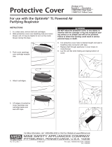
FILTER INSTALLATION
Filter Safety
• Do not use the respirator without the spark screen, pre-
filter, and the HE particulate filter (HEPA) installed. The
NIOSH approval of this PAPR is with the spark screen,
pre-filter and HE particulate filter installed using
respirator without any of these items is not in accordance
with NIOSH approval and may be dangerous to your
h
ealth.
• Replace air filters when damaged or clogged. DO NOT
wash, clean with compressed air or reuse dirty air filters.
• Use specific replacement filters specified in this manual.
Use of other filters is in violation of the NIOSH approval
of the respirator system. Refer to NIOSH respirator
approval label for system configuration.
Install the spark screen, pre-filter, and particulate filter in filter cover
exactly as shown.
Install the filter cover assembly to the blower unit by engaging tabs
on filter cover into bracket on blower unit and rotate assembly to
close. Push filter cover assembly down until latch clicks into position
securing filter cover assembly. Make sure the filter cover assembly
is secure to the blower unit body. Inspect both latching side of cover
and opposite side to see that the filter cover is properly secured.
To replace filter, push latch into release filter cover and replace filter
as shown in figure 3. Refer to NIOSH respirator approval label and/or
parts page at the back of this operator’s manual for proper filters to
be used with this respirator.
WARNING
VIKING PAPR 3350 WELDING HELMET
Particulate
Filter
Pre-Filter
Spark
Screen
Latch
Filter
Cover
FIGURE 3

12
BREATHING TUBE INSTALLATION
Breathing tube safety
•
Be sure breathing tube is properly installed or non-
filtered air may enter the helmet.
• Be sure o-ring is properly installed on tube connector and
there are no visible signs of cuts or tears on o-ring.
Replace o-ring if damaged.
• Do not use respirator if o-ring is missing.
Connecting breathing tube to blower
Align pins of tube connector with channels in blower unit receptacle.
Insert connector as far as it will go into blower unit and the turn
connector 1/8 of a turn clockwise to secure this end of breathing
tube.
Connecting breathing tube to helmet
Align pins of tube connector with channels in helmet receptacle.
Insert connector as far as it will go into helmet receptacle and the
turn connector 1/8 of a turn clockwise to secure this end of breathing
tube. If tube is twisted, disconnect one end of breathing tube.
Untwist tube and re-attach.
To remove breathing tube turn connector 1/8 of a turn counter
clockwise and pull connector out to release from helmet or blower
unit.
WARNING
VIKING PAPR 3350 WELDING HELMET
Breathing
Tube
Breathing
Tube Connector
Receptacle
O-Ring
FIGURE 4

13
SHOULDER STRAP INSTALLATION
Connect hooks (4 total) on shoulder strap assembly to belt attachment
points as shown.
VIKING PAPR 3350 WELDING HELMET
Shoulder Strap
Assembly
Hook
Belt Attachment
Location
FIGURE 5

14
RESPIRATOR CONTROLS
Respirator Use
If an alarm sounds or the blower vibrates, leave the work
area immediately. Do not remove the respirator until you
are in a safe area.
Starting the Respirator
Press ON button for 1 to 2 seconds until the blower is activated. An
audible sound will be heard and the user interface will light up. The
blower will always start at the low air flow setting (180 lpm).
Pressing the ON button again will switch to the high air flow setting
(210 lpm). The user interface will show the air flow setting chosen.
Stopping the Respirator
Press OFF button for 2 seconds until blower stops. When pressing
OFF button, an audible beeping sound indicates the OFF button has
been depressed. Beeping sound will stop and the user interface will
darken when blower unit is off.
Battery Level Indicator
This indicator gives the user an estimate of the battery life
remaining. When three full bars show up in the display, the battery
is fully charged.
Filter Life Indicator
This indicator gives the user an estimate of the filter life remaining.
When three full bars show up in the display, the filter is in need of
changing. When zero bars show up in the display, the particulate
filter is clean. As the bars appear, the filter is becoming clogged and
a reduction in battery life is expected. Operating respirator with
filter indicator showing a clogged filter will significantly reduce the
battery life/run time.
WARNING
VIKING PAPR 3350 WELDING HELMET
180
FIGURE 6

15
AIR FLOW ALARM OPERATION
Air Flow Alarm
• The control system of the blower unit maintains the air flow rates
consistently throughout the operating time. If the air flow alarm is
activated, the filter may need to be replaced and/or breathing tube
h
as become blocked.
• Always test air flow alarm prior to using respirator.
• If an alarm sounds or the blower vibrates, leave work area
immediately. Do not remove the respirator until you are in a safe
area.
Testing of Air Flow Alarm
Testing of air flow alarm must always be done in a safe enviroment.
Disconnect breathing tube from helmet. Start blower unit and block
air flow by placing your hand over the end of the breathing tube as
shown. Hold your hand over end of tube as shown until alarm sounds
and blower vibrates (approximately 15 to 30 seconds).
If the alarm does not activate return unit for repair and do not use.
VIKING PAPR 3350 WELDING HELMET
BLOCK AIR FLOW
WITH HAND
FIGURE 7

16
AIR FLOW CONTROL
Adjust Air Flow Baffle as shown. Air flow baffle allows for air to be
distributed to all three air outlets (open position) or to be shutoff
(closed position) to the forehead outlet pushing more air to the other
two side air outlets. Baffle can also be adjusted to reduce the amount
of air being delivered from the forehead air outlet. This allows the
user to adjust the amount of air delivered at multiple outlets to
provide maximum comfort. The default position for this baffle will be
open for air to be distributed to all three air outlets.
There is also a Front Air Director to change the direction of the air
exiting the front air outlet. The Front Air Director does not affect the
volume of air exiting the front air outlet but may be adjusted by the
user to enhance comfort.
NOTE: Varying the air flow baffle will not adversely affect respiratory
protection.
VIKING PAPR 3350 WELDING HELMET
FIGURE 8

17
PREPARING FOR USE
Before using Respirator – Check the Following Items
1. Blower Assembly
• Verify the air filter is proper for application and is NIOSH
approved for use with this respirator. Verify the spark screen,
pre-filter and particulate filter are properly installed and
securely latched.
2. Breathing Tube
• Make sure tube is not damaged and connected properly to the
blower unit and helmet.
3. Battery
• Verify connection to blower unit is secure and that battery is
fully charged.
4. Air Flow/Air Flow Alarms
• Start blower unit and verify air flow rate is being maintained by
checking for air flow alarm activation. Test to verify air flow
alarm is working (see page 15 for procedure).
5. Helmet/Hood
• Inspect helmet for damage and replace if necessary. If air from
blower is not being supplied to helmet, see troubleshooting
guide (page 15).
VIKING PAPR 3350 WELDING HELMET
FIGURE 9

18
DONNING PROCEDURE FOR RESPIRATOR
Respirator Safety
•
Do not enter a hazardous area until you are sure the
respirator equipment is functioning correctly and
properly worn.
• Leave the contaminated area immediately if the alarm
sounds or the blower vibrates. Do not remove
equipment until you are in a safe area.
• It is recommended that the user practice the donning
and wearing of the respirator before attempting to use
the respirator for respiratory protection.
• Do not use the powered air-purifying respirator without
all filter components or with blower turned off or
hazardous levels of oxygen and carbon dioxide may
accumulate in the helmet.
Donning respirator
NOTE: Make sure all procedures within preparing for use have
been completed, prior to donning.
1. Put the blower assembly on against your lower back with hose
extending upwards. Extend arms through shoulder straps, allow
straps to go over shoulders and belt around waist. Adjust
shoulder straps and belt so blower unit rests against lower back
properly.
2. Start the blower unit by pressing the ON button. Adjust air flow
rate.
3. Connect the hose to the helmet assembly. Put on helmet and
adjust so helmet fits snug on head. Tighten drawing string of face
covering to establish a seal around head.
Respirator removal
NOTE: Leave contaminated area before removing the helmet
and blower unit.
1. Take off helmet and disconnect hose from helmet.
2. Turn off blower unit by pressing OFF button.
3. Release belt, remove straps from shoulders and remove blower
unit off of your lower back.
After use, the respirator components must be cleaned, inspected
and prepared for reuse (battery charged).
Respirator Maintenance And Storage
•
Replace damaged or dirty air filters. Filters cannot be
washed or cleaned with compressed air. Never reuse a
dirty air filter.
• Never use solvents or abrasive cleaning solutions to
clean the respirator. Keep water and other fluids out of
blower assembly.
Maintain accurate records of filter replacement and respirator
maintenance.
The respirator components should be cleaned after each use. Use of
a soft cloth dampened with a mild soap and water solution to wipe all
external surfaces of blower unit clean. Allow to dry.
Factors including product usage and workplace contamination levels
affect the life of the filters. Replace filters if air flow is reduced
because of dirty filter and according to the filter change schedule
established by your Safety Director and an Industrial Hygienist.
Inspection of blower assembly and breathing tube after each use is
good practice. Replace breathing tube if damaged or if inside of tube
is dirty.
Storage of respirator should be in a clean, dry, cool place with the
filter and battery removed for blower assembly if respirator will not
be used for an extended period of time.
WARNING
WARNING
VIKING PAPR 3350 WELDING HELMET

19
PROBLEMS
(SYMPTOMS)
POSSIBLE
CAUSE
RECOMMENDED
COURSE OF ACTION
N
o air flow to helmet from blower.
Blower supplies insufficient air to
helmet.
Low airflow alarm (audible & vibrato-
ry).
Battery alarm (audible & vibratory).
User detects odor or taste of conta-
minants or feels eye or throat irrita-
tion.
Battery run time is too short.
The motor runs “faster than normal”
(increased sound level).
1
. Blower not ON.
2. Battery not charged.
3
. Battery connection not being
made.
4. Breathing tube blocked.
1. Breathing tube connections not
properly connected.
2. Clogged filter.
1. Breathing tube is blocked.
2. Filter inlet is covered.
3.Clogged filter.
1. Low battery.
1. Incorrect respirator for application.
2. Hose connections loose allowing
air to enter downstream of blower.
3. Filter
1. Inadequate charging.
2. Clogged filter.
3. Battery faulty.
1. Filter is getting clogged.
1
. Press ON button.
2. Charge battery.
3
. Verify battery pack is securely
latched into blower unit.
4. Clear obstruction from blower out-
let and/or hose.
1. Check breathing tube connections
to blower and helmet.
2. Replace filter.
1. Clear obstruction from blower out-
let and/or hose
2. Make sure inlet to filter not
restricted.
3. Replace filter.
1.Charge battery or replace battery
as required.
1. Consult onsite Industrial Hygienist
or safety director for proper equip-
ment for work environment.
2. Check hose connections to blower
and helmet.
3. Leave area wearing respirator.
Check filter and replace if neces-
sary.
1. Fully charge battery.
2. Replace filter.
3. Replace battery with new one.
1. Replace filter and pre-filter as
required.
TROUBLE SHOOTING GUIDE FOR RESPIRATOR
VIKING PAPR 3350 WELDING HELMET

20
AUTO-DARKENING HELMET SECTION
HELMET/LENS INFORMATION
The Auto-Darkening Lens in this welding helmet will automatically
change from light state (Shade 3.5) to dark state (5-13) when arc is
initiated.
The lens automatically returns to a light state when the arc stops.
Before welding, match your welding application to the shade
indicated on the shade guide setting chart. (See Page 20) Also adjust
the sensitivity setting to your welding application/environment.
This Auto-Darkening Welding Helmet is designed for use with
GMAW, GTAW, SMAW welding, or Plasma Arc and air carbon arc
cutting.
The Auto-Darkening Lens provides protection from harmful UV and
IR radiation, in both dark and light states. No matter what shade the
lens is set to, the UV/IR protection is always present.
The Auto-Darkening Lens contains four sensors to detect the light
from the welding arc, resulting in the lens darkening to a selected
welding shade.
• Do not use solvents or abrasive cleaning detergent.
• Keep the sensors and solar cell clean.
• If cover lens is spattered or covered with dirt, it should be replaced
immediately.
• Use only replacement parts specified in this manual.
• Do not use the helmet without inside and outside cover lenses
properly installed.
• Do not use the auto-darkening lens if damaged by shock, vibration
or pressure.
VIKING PAPR 3350 WELDING HELMET
/