Page is loading ...

T
T
-.-
I
!
_.
MODEL "G" TRACTOR-
Allis--Chalmers Mfg. Co.
d> - TRACTOR DIVISION
MILWAUKEE, WISCONSIN-
U. S. A.
.;~
#CU 279 Xl
-~"..•....
,. )

·. ~.
ALLIS-CHALMERS MANUFACTURING CO.
Milwaukee, Wisconsin
Allis-Chalmers Model "G"
Allis-Chalmers HD19H
ALLIS-CHALMERS MODEL "G"
Allis-Chalmers Mfg. Co., Milwaukee, Wis.-
1948-1958
1948
Air Cleaner: Donaldson, oil bath.
Battery: Auto-Lite.
Brakes: Two, operated by foot pedals.
Carburetor: Marvel-Schebler,
% in.
Clutch: Rockford, single dry plate.
Generator: Delco-Remy.
Governor: Continental, centrifugal.
Ignition: Delco-Remy, distributor and coil.
Lamps: Guide Lamp.
.Oil Filter: Own.
Radiator: Perfex or McCord, fin and tube.
Radiator Cover: .
Spark Plugs: Auto-Lite AN-7.
Starting: Delco-Remy.
Data: H.P.-Neb. Test No. (not tested).
Number of plows recommended: One,
12-in.
Engine: Continental N-62; 2%x3%, 1800
r.p.m., 4 cylinders, L-head, cast en bloc.
Piston displacement 62 cu. in.
Pulley: 6x4, 1950r.p.m. and 3070f.p.m. at
normal engine speed.
Speeds: M.P.H. Forward 1.58, 2.19, 3.46,
6.71 and 2.54 reverse.

1
-
,
, j
,'-"'"
"
SERVICE MANUAL FOR THE tv«:>DEL''0'' TRACTOR
The {'ngine for the model "c'· tractor is mounted in the rear of the tractor.
For purposes of identification, the engine will be referred to as crank end.
flywheel end, manifold side and generator side. The No. I cylinder will be
at the crank end of the engine.
The design of the model "C'· tractor lends itself to a variety of procedure
for following practical repair work. The following general procedure may
be followed in removing major assemblies from the complete machine.
The complete engine may be removed as a unit. The engine must be removed
to do any repair work on the dutch, throwout bearing. flywheel or oil pump.
:.': The engine and clutch housing may be removed as a unit if the differential
is to be removed or the transmission dismantled.
Removal of the complete engine assembly or of the clutch housing must be
~a~e if the belt pulley drive gear or engine intermediate gears need ser-
vIcIng.
The adjustment of the transmission shaft bearings and removal of the special
low reduction gear may be accomplished if the to rque tube is removed from
tractor.
If the complete transmission and differential is to be repa'ired. the torque
tube, the engine, clutch housing and the two wheel axle aStiemblies must be
removed.
• • •
C - I
•

MODEL "G" TRACTOR INDEX
(' .
·SUBJI-.CT
AIR CLEANER
A t-.1t-.tF: Tl:'. R
BATTF.RY
nf-~l.T PULU-;: Y
.BRAK~:S
BRAKf>PFDAL AD] USTMENT
CAMSHAr'T
.f:ARBURETOR
CONNF.CTING ROD
CLUTCH
CI.UTCH HOUSING
CLUTCH HOUSING & ENGINE REMOVAL
C l.UTe H THROWOUT BEARING 81 FORK
CRANKSHAFT
CRANKSHAFT OIL SEALS
CYLINDFR HEAD
DIAGNOSIS OF TRACTOR PROBLEMS
DlFFFRFNTlAL
DlST HIBUTOR
DHAWBAR
fo~NGINF.
F'.NGINI: OILING SYSTEM
1'~NGINr: RE:.MOVAL
I-:l.FCT RICAL SYSTEM
FAN BI-'.LT
FAN ASSEMBLY
FLYWHI-:1-2L
& RING GEAR
FRONT AXLE.
&I SPINDLE
FRONT W HEF:LS
FUr.'.L
FU~:L FILTER
FUI-:L TANK
GF.AR SHIFT
GF:NF.RATOR
GOVF.~RNOR
GOVERNOR WEIGHT ASSEMBLY
HOOD & HOOD SUPPORT
HYDRAULIC PUMP
IGNITION SWITCH
INTF.:R MEDIATE GEARS
LIGHTS
LIGHT SWITCH
LOW GEAR (SPECIAL)
MANIFOLD
OIL SEALS, FRONT'" REAR
OIL PUMP
OILING SYSTEM
OIL PRESSURE RELIEF VALVE
PISTONS
&. RINGS
RING GEAR
&. FLYWHEEL
RADIATOR
RE:I::L WHEEL
& AXLE HOUSING
SPF.CIFICA TIONS
STARTER
STEERING GEAR
SPARK PLUGS
SPECIAL LOW GEAR
TIMING GEAR COVER
TIMING E.NGINE
TRANSMISSION
VALVES
WIRING DIAGRAM
Supplement No. 28
G
SECTION
8
11
"" -'~. ~ 40'·;
19
19
lO
IZ
ZZ
zs
Z6
17
Z6
18
19
16
31
14
9
Z4
17
10
13
7
Z7
36
36
30
30
34
11
IS
16
7
39
11
Z6
I I
10
3Z
36
17
19
Z4
ZI
ZZ
Z7
S
Z8
3
Il
3S
3Z
15
14
3Z
ZI
10
G-Z
SPECIFICATIONS
3
3
3
3
4
3
3
3
S
5
5
5
3
4
S
S
4
.~.
,..f

SPECIFICAI1Ul""
ENGINF:
F:NGINF.
CRANKSHAFT
1.999 to 2.000
.0015" to .00l"
,0001"
,003"
Adjustable
.OOZ" &. ,DOh"
.003" to ,007"
75 to b5 ft. Ib~.
5 to 10 ft. Ibs.
.002"
& .020"
Type
C>'linders.
Bore
Stroke
Piston Displacement
},',nginc Speed Full Load
r~ngine Speed High Idle
Fngine Speed Low Idle
Conlpression Ratio
Prior to (....ng. l3988
I·:ff. On Eng.l3988
Firing Order
Rotation
Conlpression Pressure
(Starter Speed)
AIR CLEANER
L-Head 4 cycle
4
2-3/8"
3-1/2"
6l Cu. In.
1800 H.P.M.
2100 R.P.M.
500 R.P.M.
5-3/4 to 1
5-5/b to 1
1-3-4-2
Clockwise
90 to 95 lbs.
Main Bearings
Dia. Journal
Clearance
Maxin1um - Replace
Replace shaft if out of
round or taper
F~nd Thrust
Shims
I'~nd Clearance
Main Nut Torque
Pal Nut Torque
Undersize Bearings
CYLINDER BLOCK
Bore Size
Top
Z.376"
.00 1 "
CAMSHAFT
Type
Capacity
TSV - 13
Updraft
5/8" SAE
7/16"
1/4" from nearest edge
of float to top of bowl
approx. 1-7/8 turn
open
DISTRIBUTOR
Zl rol
3/ IE
Z-7/3
500 to ZIOO R,P.J
.0015" to .003"
.OOB"
3Zc
.OZO'
,18 to .Z3 Microfarad~
Battery distributo'
Clockwisl
Mark Advance 3
1 Z
1 5
Bottom 1.,3765" - .001"
Piston Clearance ,OOZ"
Rebore at .010" or mure
Ridge - Remove if replacing Rings
or bearings
Needle 8earing
Pivot Ball
Spring - free length
Speed Range
Gear 8acklash
Maximum
Cam Angle
Point Gap
Condensor
Type
Drive
C rank Pulley Timing
Advance - Auton1atic
Hunning Advance
GOVERNOR
Oil 8ath
1/2 pint
1- 3/4"
1-1/4"
.003" to .0045"
.007"
.147" to .149"
.005"
.007"
15 to lO ft. Ibs. torque
Journal Size
Front
&< Center
Rear
Clearance
Replace-maximum
Thrust Plate
F:nd Clearance
Replace at
Thrust Plate
Capscrews
Idle Needle Adj.
Marvel Schebler
Type
Throttle Flange
Venturi
Float Level
CARBURETOR
CONNECTING ROD
LUBRICATION
Length
Squirt Hole
Piston Pin Oil Hole
Capscrew
& Shake Proof
Lockwasher
Side Play
Replace at
Shims
Journal Size
Bearing Clearance
Maximum- Replace
Undersize Bearings
Capsc rew Torque
5- 3/4"
1/16"
5/3l"
5/16"
.006" to .010"
.0 14"
None used
1.499 to 1.500
.0015" to .00l"
.004"
.00l"
&< .0lO"
lO to l5 ft. Ibs.
G - 3
Type
Pump
Pressure
Capacity
Filter
Oil
(according to
Press\
Gear t~
7 to ZO 1
3-1/Z q
own-cotton wa
SAE lOW to SAE
load
&< temperatu

OIL PUMP
ENGINE SPECIFICATIONS (ContI d.)
PISTON RINGS
7-1/2
Clt, per min,
.001" to' .002"
.005"
.004"
.004"
.002" to .0035"
3 pe r pi"ston
Tapered
Indicates to p
Ventilated
Expander used
Expander used
,007" to ,Oil"
.0015" to .0035"
.0045"
Chromium Plate:!
Clearance
Number used
Type - l- roduction
Compression (2)
Pit Mark
Oil Control (I)
Standard Size Service
Top Compression
not tapered
Second Compression
tape red
Oil Control
Replace rings when gap inc reases above
,012", plus three times the bore wear,
F:nd Gap
Ring Land Clearance
-----R-eplace at
,006"
----- 7 Ibs,-
lO Ibs,
pailltt'd greell
1-15/16"
loose to ,DOl"
press
,0005" to ,0025"
loose
Treated
paper
,007" thick
Gt>ar Backlash
fv1axinmnl Gear Backlash
Tooth Tip to Body
Gear end clearanCE:
Drive Shaft Clearance
iI1 bushing
DJ-ive Shil-ft Clearance
in bushing maximunl
Driven Gear Shdft _001"
in body
Driven Gear Shaft
in block
Oil Pump to block gasket
Oil Pump cover to body
gasket - lead
Capacity
Pressure
Minimum
lvIaxirn_um
Spring (relief valve)
Length (free)
PISTON
Cdst Iron
Oversize Rings ,020"
&. .040"
Not to be used until block is rebored
.5433"
to- .5435"
,003" and ,005"
Light push fit
Very light push fit
.0003" loose or noisy
14 M.M.
.025"
A.C. 45 or autolite AN?
Size
Point Gap
Intake Tappet Clearance ,01
ZIt cold
Roto Exh. Tappet Clearance .01 Z" cold
Timing Marked gear
Inlet Opens T .D,C.
Inlet Closes
350 after B,D.C,
Exhaust opens 40° before B.D,C,
Exhaust closes T .D.C.
Seat Angle 450
Seat Diameter 57/64"
Maximum Seat Width 1/16"
Intake Stem to Guide Clearance .001-8"
Replace at .005" Maximum
Exhaust Stem to Guide Clearance ,0035"
Replace at .007" Maximum
Pilot Size 5/16"
Guide Length 1-21/32"
Location 25/32" from top of block
to top of guide
factory reamed to size
free length 1-13/16"
1-3/4"
Service Guides
Valve Springs
Replace if less than
VALVES
SPARK PLUGS
2.362" to 2,364"
2.3735"
to 2,3750"
2-9/31."
2,362" to 2,364"
2,3735" to 2.3750"
2-9/32"
Releived
,DOl"
.0035" ,.020", .040"
l/l" above skirt end
450 each side of pin
True Round
,0035", ,020", ,040"
Bosses releived at
F:nd of pin
Tapers Out
Tar_ers Out
Piston
Sizes
Dimensions
Top
Ski rt
Height
Carn Ground
Si
ze s
Dinlensions
Top
Skirt
Height
Aluminum
Diameter
Oversizes furnished
Fit in Piston
Fit in Rod
Replace
PISTON PIN
G-4

CHASSIS SPECIFICATIONS
Location Left Side
Speed 1950 at 1800 of engine
Ratio Pulley to Engine 1.08 to 1
High Idle 2275 R.P.M.
~ize 6" dia. 4" face
r
fO
r
1
i
BELT PULLEY
BRAKES
Diameter
CLUTCH
Type
Size
Springs - free length
COOLING SYSTEM
Type
CROP CLEARANCE
Optional Equipment
Internal expanding
7"
Dry Plate
6-1/2" dia.
1-9/16"
Thermo Syphon:
GENERAL DIMENSIONS
Tires
Front
Rear
Tire Pressure
Front
Rear
Wheel Spacing
Front
Rear
Wheel Base
Length - Overall
Height - Top of Steering Wheel
4 :00 x 12
6 x 30
15 lb.
12 lb.
36" to 64"
36" to 64"
68"
116"
56"
ELECTRICAL EQUIPMENT
Battery 6 volt 70 ampere hr.
Generator (Delco-Remy) 2 charging
rates
High Rate approximately 13 amp.
Low Rate approximately 3 amp.
Starter (De1co-Remy) 6 volt
Under Rear Axle
Under Drawbar
FAN
17-3/8"
13"
POWER
Drawhar
Belt
Recommended Load
RADIATOR
Type
Operating Pressure
Capacity
TRANSMISSION
8:00H.P.
10.5 H.P.
-12"plow
Pressure - Tubular
7 Ibs.
6-1/2
qt.
Type
Size
Blades
F an Speed at 1800
engine R.P .M.
Ratio-Crankshaft to
fan pulley
FRONT AXLE
Castor
Camber
Steering
Toe In
FUEL SYSTEM
Suction
ll"dia.
4
2900 R.P.M.
1 to 1.616
None
5 degrees
Semi-Reversible
None
Speeds
Low (Special - Optional)
First
Second
Third
Reverse
Lubricant Capacity
TURNING RADIUS
Nith'Brake
Without Brake
WEIGHT
1.6 M.P.H.
2.26 M.P.H.
3.57 M.P.H.
6.91 M.P.H.
1.96M.P.H.
b qt.
6-1/2
ft.
E-l/2 ft.
1400 Ibs.
Type feed
Fuel
Tank Capacity
Carburetor
Float Level
Fuel Filter
Gravity
Gasoline only
5 gal.
Updraft
1/4" from nearest
edge of float to top of bowl
Felt
& Bowl
G - 5

F:':'NGI~~HOODAND HOODSUPPORT
-0
Removal
The hood and hood suppc·rt IndY be' removed
together if the, capscrcws, attaching the hood
to the radiator are removed and the two
short capscrews, spal..ers,'the oue long cap-
screw and spacer are removed from the lower
portion of the hood support at the crank end
of the engine. Remove the tail light from the
hood support.
If the"hood alone is to be removed, the bolts
Inust be removed from the hood at the top of
the hood support •
.ELili...,ASSEMBLY
Removal
Loosen the gene rato:l."<'.adrnove it toward
engine in order to rt::nove tension h'orn the
fan belt. Remove the air cleaner and the
instrwnent box from the fan shaft bracket.
Remove the carburetor dir inlet pipe and
bracket from the cylind~r head. Remove
the four nuts attaching JQ~_fanshaft brackets
to the cylinder head. .. -.-- .
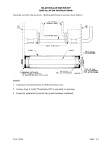
PULLING FAN~·· -~. __ ...•
To remove the fan
h-OlU the shaft, it is neces-
sary to remove the £.'Ulbnicket hon'l the bear-
ings and attach the OTC puller as shovmusing
a 1/2" x 2"spacer equipped with a 60° center
between the puller screw and the fan shaft.
The pulley may be removed irom the shc-.fi:
with the same tool. This wo;-k>:naybe done
more satisfactorily if a presE is available"
Inspection
Inspection of th{;
fiiIl may b~ acco!'l:l~li~~(>d
G - 7
without removing it from the engine. Check
the bearings for wear and roughness. They
should not be rough or worn more than .006'1.
Check the fan belt sheave contact surface for
wear caused by the fan belt. If the wear in-
dicates that the surfaces are curved or that
the belt bottoms in the sheave, the sheave
should be replaced. The fan shaft should be
straight. Check fan blades fa r loose rivets
or cracks.
lUBE OR SOCKET
TO FIT OVER SHAfT
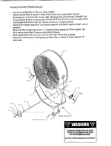
INSTALLING FAN SHEAVE
Assembly
Press the front bearing, bearing spacer and
fan sheave on the shaft until the sheave is
flush with the end of the shaft. Place the
front fan shaft bracket on the bearing and
instal: the snap ring. Press the rear bearings
and '::>racketsand fan blade as sembly on the
st.3!.f: until the bearing brackets measure ex-
actly 11-1/4" center to center between the
bearing bracket attaching holes. This method
must be followed in order that the fan sheaves
will line up with the generator and crankshaft
sheaves and to make sure that the bearing
bracket centers will fit the cylinder head
studs of the engine.

AIR QUT1ET TUBE DRAIN
16\,<:u.T~~";~
.............--- .•.._-,•....~
'Check the air inlet pipe, air outl·~t t.ube drain
filter and air cleaner for leaks. AnY'.1eaks
in
,air cleaner body or between body and car-
buh~tor will defeat the puqjosf'ot:the~air tlEian-
er':"Check tile drain hol~ at the "lowe'r-end'-of the
ca'rburetor
:air'inlet pipe ~ahd'rn.ake sure the
str'~'in'er'i s~;i
It 'pfac'(' -;-:'If'in i~li'i'ng -p¥ 'loC;s~" it
sh:p~~dhe'repla~ed-.Ba~kwash Hit;fiiter eI~n'lent,
ma..king :,S,urf.'tha,t all)oreigJ;l 1'1lat(;rial i:s re-
moved from"the' cl('ment and the i'nh~t side of
the ai r cleane
I' bod}'.: ";,':, ' ,
'R~moval.,
.oj;;
, L~16<>ien1;Oi'e~'hosec onri'ec t-i 0'0S"'<at!'e a~'h)~ri'd of
,;:th~~~r·D~-r~.fo·~·'air·· inleCpipe:~and\ i~in'o"vp2:>the
,>::twfivitufst:Jiltt"iCch"ihg:~the1ai'i4 inlet~lii:pe't:s'upport
io~tn~;:ytirider;·Il~'cid.;' Removeit~e'lW~l%::;ai:lii,~h-
~ng~~'[arJ!;dE!ane'r'Dodrto~fHe'r'€~f;<Icititl>ra-c ket.
".
- ,
,". ~
.. :;.1
, ~'- ..:,;.:o~,, -:-2'a:Wfr"~0n._..,
----~- "'...•....•. ""'''-:'-.~-~~~
;."jJ::,'i.'
-4;"-;; "H}Q
:~~)_!.~:i-$..5!1j' lr>
'{f--iC ~1::.F;' ~.hp~~.
-~' ..• "".::
~. ~.••""..f ~ ._
., ~ , ~~:. .
~..; .: ,>;- •• , •...•
~~ -J
l:::~d ~tij
~;. qo:!
';'
Removt' fue 1 tdnk and fender's as an assembly.
Rernove the engin~ hood and disconnect the
two brake rod return springs from the lowe r
side of radiator. Drain the radiator and re-
move the uppf'r and lower hose from radiator
inlet and outlet. Remove the two capsc rews
attachillg the radiator to the clutch housing.
The cooling system is of the thermo-syphon
type and to operate must have the cooling
solution maintained above the lower edge of
radiator inlet tube. The cooling solution tem-
perature will vary with the prevailing weather
temperature and will be hottest on the days
when the outside tempe rature is hottest. This
system is automatic and the speed of circulation
varies with the difference between temperature
of the radiator and the water jacket of the
engine. The engine will operate at a temperature
even in the coldest weather, which tends .to pre-
vent the formation of condensation in the crank ••
case. 1£the engine should overheat, check the
fan belt for slippage. Check the radiator for
leaks and accumulation of foreign material in
Removal.
Inspection
, ,
;.~~s~'.~..' -.;~;1;\:$..~
:: ..
--.~,-~.~
, ,..--:
RADIATOR
"
... '.-~.
the radiator core. l('h~r-d'::d~ alkaline water
has been used in the cooling :-Systme, check the
inside of the radiator and cylinder block for an
accwnulation of scale deposit., Check the hose
connections and hose for deteril'r'ation or col-
lapsing. The spring loaded pressure cap re-
tains approximately 7 lbs. of pressure in the
cooling system and raises the boiling point
to approximately
2300 Fahrenheit. The pressure
cap also incorporates a vacuwn valve which is
set at
1-1/2 ounces to relieve the system of
vacuum when it is cooling off. When draining
the cooling system, it is best to loosen the
radiator cap so the s}'stem will not become
air-bound, which rnight prevent dr-dining.
CA UTION: Do not remove the radiator cap
if the engine is overheated. Remo\'e cap \\iter
engine has cooled.
Assembly
Install the radiator on the tractor using a st:al-
ing compound at the hose connections to pr('vent
leaks. Due to the higher operating temperature
of the thern1o-syphon system, it is not advisable
to use alcohol as an anti-freeze. F,thylene-Clycol
or some similar solution should be used as an
anti-f ree ze.
G-8

Removal
DRAWBAR
nut from the drawbar pivot pin.
Remove the four capscrews attaching the
drawbar guide to the cylinder block anti re-
move the guide. Remove the cotter pin and
~.
G-9
For engine removal, remove drawbar ·guide
and swing drawbar to one side.

EU':CTRICAL SYSTEM
...•
RED TR.
CUTOUT RELAY
HEAD LIGHT
CONNECTOR
TAIL LIGHT
WIRING DIAGRA
~,-"--.j
-
}
-
III - Discharge side of anlmeter to cutout.
HZ - Resistor to generator field terminal.
1/3 - Ignition switch to coil to primary dis-
tributor lead.
#4 - Light switch to headlight
& tail light.
H5 - Change side of ammeter to starter .•
1/6- Generator armature terminal to cutout
relay.
#7 - Discharge side of ammeter to fuse.
#8 - Discharge side of ammeter to ignition
switch.
When any service is to be performed on the
electricAl ~ystem. the battE'ry ground strap
should be removed. Removal of the battery
ground strap will prevent shorting and damage
to Ammeter pr AOy pt the relative parts of
the e'ptire elettric;al system.
LIGHT SWITCH
The light switch is n'lounted on the instrument
panel which is located under the engine hood
and is attached to the front fan bracket. The
light sw-:'::h incorporates the generator con-
trol, which is of the two step system, having
a high and low charging rate. The fuse for
the lighting system is also mounted on the
light switch.
A fuse of either a 10 or 15 amp.
capacity can be used. The operation of the
light switch isas follows: When the switch
is all the way in, the lights are off and the
generator charge rate is at the low P?sition.
With the light switch pulled out to the fi
nt
stop the lights are on and the charging rate
is in the high position. With the light switch
pulled all of the way out, the lights are off and
the charging rate of the generator is in the
maximum position. This manuell control of
the charging rate is accomplished by a resis-
tance unit on the outside of the light switch
G-IO

IGNITION SWITC H
r
!-n
which is cut into or out of the circuit and
limits the arnoWlt of electrical current allowed
to pass ttnough the field coils of the genera:
The ignition switch is also mounted on the
instrument panel and is used to complete the
tor. The generator charging rate is approxi-
mately 3 amperes in low position and 13 am-
peres in high position.
ignition circuit.
AMMETER
The ammeter is mounted on the instrument
panel and indicat~s the rate of generator
charge or battery discharge to the electrical
system.
Inspection
Inspect all wires and make sure they are free
from cracks, broken wires or terminals and
free from deterioration. They should also be
I.
kept free of grease and dirt accumuiatibn
All grommets should be in place and ih good
condition.
Assembly
See the wiring diagram for the connections
which must be made to complete the wiring
system. Keep all connections clean, bright
and tight.
Removal
The headlight is mounted on the front frame
of the tractor and may be removed if the
headlight wi re is disconnected at the front
frame. If the wire is to be removed from the
torque tube, it is advisable to place an exten-
sion on the wire that may be left in torque
tube when the light wire is drawn out. With
this extra extension it is possible to replace
the head light wire without any difficulty.
HEADLIGHT AND TAIL LIGHT
Both lights use single contact 6 - 8 volt bulbs.
The headlight is 32cclndle power and the tail-
light is 15 candle power. With the single con-
tact bulbs, it is necessary to have all the
lamps and tractor parts which are used to
complete the circuit, clean, bright and tight.
Dull reflectors cause inefficient lighting.
The reflectors should be replaced if dull or
polished by the use of lamp black or silver.
polish. In polishing the reflector, use a soft
cloth that will not scratch the reflector. Al-
ways use a new gasket between the lamp and
The tail light is mounted on the hood support reflector to prevent any moisture from ac-
and the wire is connected directly to the light cumulating on the reflector surface.
swikh. GENERATOR
Removal
Remove the capscrew from the generator
brace and the wires from the field terminal
and ammeter or cutout terminals of the gen-
erator. Remove the two bolts from the lower
pivot point or the two nuts attaching the gen-
erator mOWltingbracket to the cylinder block.
Inspection
Refer to the general section of the Service
G-ll
Manual for details on the generator. The
generator should be repaired only by an
authoriz'ed service station.
The generator is driven by the fan belt. To
adjust tension, loosen clanlp screw and move
generator away from cylinder block. See
"fan belt".

STARTER
.;'
Removal
lnspectio n
. .
See the general section of the service mimual
for details on the starter. The starter should
be repaired only by an authorized service
station.
Ch(~ck the battery terminals for cleanliness
and tightness. All connections must be clean
" :c·_:.:' and tight.
lri~cold\,veatner ifthe Marte'i'does nof enga'ge
the flywheelprornptly ,''the :starter drive screw
threads should be washed out with kerosene.
,Do not lubricate the starter drive threads but
leave the kerosene as the only lubricant.
: ~ -.'. ~...-. .
When r~installirig battery cable, place it under
radiator and not around side of radiator.
-
0-
\
\
,
.-e =
'.
SHAFT
VALVE
CHOKl SHAFT
ROAT
CARBURETOR
The carburetor is a tv1arvel-Schebler TSV-13.
The']el sizes are not marked on the jets of
this carburetor and reference must be made
to part numbers to be sure the correct parts
are obtained.
ReITX>val
Remove the carburetor air inlet pipe, the
choke rod and the fuel line. Disconnect the
carburetor link rod to the 'governor. Remove
the two capscrews attaching the carburetor
to the intake manifold.
Inspection
Inspect the choke shaft and throttle shaft for
wear in the body. Any wear at these points
will allow the entrance of dirt to the engine
and cause uneven operation at low speeds.
Check the float and the float valve {or leak-
age. Check filter in intake pipe for loose
felt through which dirt might enter.
Assembly':
The float level should be set with the float
1/4" from the top edge of the bowl or 1/4"
between the bowl gasket and the nearest edge
of the float. The idle needle is set approxi-
mately 1-7/8 turns open. The float may be
set by bending very near the float axis, being
sure not to cause the float to stri'ke the edges
of the bowl.
With the engine heated to normal operating
temperature, the idl~ stop screws should be
adjusted to permit the engine to operate at
approximately 500 r .p.m. at low idle.
G - lZ
T

FAN BELT
Removal
I
i
Loosen the generator brace and move the
generator closer to the cylinder block. Re-
move the upper right capscrew and spacer
attaching the hood support to the cylinder
block.
Inspection
Checkthebelt andthe conditionof the sheaves.
The sheave side should be fiat and smooth
and the belt should not bottom in the sheave.
If the belt is grease-soaked, deteriorated or
broken, it should be replaced.
AssemblY.,
Check the fan belt tension opposite the gen-
erator pulley on the straight side of the belt.
The belt should move in or out approximately
one-half inch from the straight line. In-
sufficient tension causes belt l';lippage or
excessive tension places an overload on the
front fan shaft bearing or the generator bear-
ings.
G-13

DISTRIBUTOR
••..• -.-- .-t---
,..,.::.. ~.: '. -: '. -.- ..
CONDENSOR
--'-- ---' -_.
. ..~.
.- .....•... ~--- ..
',~!.~;~,DISTRIBUTOR CAP
;;~~~;~J:,','
j
,/
.__rP,'
"
.,
t,: .''.., ~.'.~ ~
,fi:.~'Q,:" ,
. ,
DUST SHIELD' ,;,' ROTOR
, , ,
,
,
Removal
Remove th~ spark plug wires and coil wire
wire from1:he top of the distributor. Dis-
connect the;primary coil wire from the coil
to the side' of the distributor. Loosen the
clamp screw at the base of the distributor
and pull distributor up out of engine.
Inspection
Check the breaker points for pitting or wear.
Assembly-'
To set the breaker point gap the distributor
rotor and the dust shield must be removed
from the distributor. Turn the distributor
until the points are separated to their widest
position.
Loosen the lock screw on the fixed point and
turn the cam screw until the points are sepa-
rated .020". Tighten lock screw and recheck
point adjustment.
To time the engine, turn the engine \mill No.1
cylinder is at top dead center on its com-
pression stroke and the timing mark on the
fan pulley is located in the center of the tim-
ing inspection opening directly below crank
support in the hood support. Hold the dis-
tributor with the coil wire terminal pointing
toward # 1 spark plug, and the rotor pointing
towards the clip farthest from terminal. Enter
the distributor into the engine block in this
position. As the distributor enters the block
and the gears mesh, the rotor will turn
slightly in a counter clockwise direction.
Clamp the distributor in place partially and
turn the distributor body in a counter clock-
wise direction until the points just start to
open. Clamp the distributor body securely
in this position. This will place vent in dust
shield downfor proper drainage. Place No. I
spark plug wire directly above the rotor and
then proceed around the distributor in a clock-
wise direction placing 3,4, l spark plug wires.
Place the high tension coil wire in the center
outlet of the distributor cap. Attach the bat-
tery lead wire from the coil terminal to the
terminal on the side of the distributor body.
Use a goodgrade of rubber cement or shellac
on the rubber nipples on the distributor to
spark plug wires and high tension coil lead.
The distributor is a Delco-Remy model
# 1111708 and all repair parts and service
should be obtained from United Motors
Service.
G - 14

r
rO
r
r
TIMING GEAR COVER
Removal
Remove the hood and hood support. Dis-
connect the carburetor link rod and the gov-
ernor spring. Remove crank jaw. Use twc
3/8" caps crews and pull crankshaft pulley
as shown. Do not run cnpscrew throug};
against die cast cover or pry against cover
as it may be easily damaged.
Inspection
See "governor" and oil seals.
Assembly-
Tighten capscrews to 15 ft. lbs. torque.
--"--- --~.
PULLING CRANKSHAFT PULLEY----
GOVERNOR & GOVERNOR WEIGHT ASSEMBLY
Removal
Remove the hood and hood support and the
fan belt. Pull the crankshaft fan drive sheave.
Disconnect the carburetor throttle link rod
from the carburetor and the governor spring
from the governor arm. Remove the timing
gear cover from the engine.
Reznovethe snap ring from the governor shaft
and turn the shaft until the tapered groove pin
can be driven out of the governor arm. The
shaft and lever assembly can be pulled from
the timing gear cover. A 3/16" thrust pivot
ball is used under shaft. The needle bearing
may be driven from the cover.
Assembly
If the needle bearing has been removed, it
should be replaced with a new part anc
pressed into place. Install the lever and
shaft assembly in the timing gear cover using
a newdust seal. Be sure pivot ball is in posi-
tion. At any time when the timing gear cover
is reznoved a new crankshaft oil seal must be
used. Tighten the timing gear cover capscre'l.\
to 15ft. lbs. torque.
To adjust the governor, back out the gover-
nor bumper spring adjusting screw entirely.
Place the throttle lever in the full speed po-
sition andhold the carburetor in the full speed
position. Adjust the carburetor link rod until
it just fits between the governor arm and the
carburetor. Adjust the ball joint at the end
of the carburetor throttle link rod until it is
free of all slack but not tight. The throttle
rod is provided with a stop to keep the en-
gine from being over speeded. Make sure
this cotter pin stop is in place. Be sure that
the throttle rod has not been bent at the spring
end which would cause interference with the
spring.
The governor bumper spring adjusting screw
is provided to eliminate surge from gove~-
nor. It is usually not necessary to use this
screw - however, if the engine does surge
G - 15

the screw should be turned in slowly until
surging is overcome. If the surge screw is
turned in too deeply, it will increase the
r.p.IX1oat which governor action takes place.
This increase would be from low idle to a
maximum of 700 r.p.m.
Governor Weight Assembly
Removal
Remove the timing gear cover and the gover-
nor thrust cup assembly. Remove the gover-
nor spider and weight assembly from the
timing gear.
Inspe-ction
The governor thrust cult assembly fits the
camshaft with from .OOZto .004" clearance.
It should be replaced if this·clearance -ex-
ceeds .OOS"or if-the cup is worn at the weight
riser contact surlace. Check the vent hole
in the camshaft behind the thrust cup shaft
and be sure it is clean and free of any foreign
material •. If this hole becomes plugged, the
governor wl1lbe inoperative due to the vacu-
um created behind the thrust cup shaft. Check
the governor weight for wear on the riser
and any wear at the hinge points. The assem-
bly should be replaced if the hinge pins are
worn more than .006" -
CYLINDER HEAD
Removal
Remove the hood and hood support, carbu-
retor air inlettube, air cleaner, instrument
panel, spark plug wire grommet holder !Uld
fan assembly. Drain the radiator and remove
the upper hose. Remove the balance of the
studs and nuts from the cylinder head.
Clean the carbon from the cylinder head and
check the head for leaks or cracks and scale
accUD1Ulation.
Assembly-
Install the head using a new gasket. Tighten
the stud to 55' pounds torsion following the
chart.
G - 16
(Qr15 (Qt-3 ©-4 <Q)-13
~6 ©-,o 2~ i:f719A])
17 ©rl 1,© ©,,8 20 0
(Q) @ @ (Q)
©r18 0 12 (Q(6 ~ 9 0 14-©)

Removal
OIL SUMP
oughly and inspect the screen for broken
mesh
Remove the drawbar guide and swing the
drawbar to one side. Drain the oil sump
and remove the small cover over the lower
portion of the clutch housing. Remove the
capscrews attaching the oil sump to the
cylinder block.
Inspe ction
Clean the oil sump and pump screen thor-
Assembly.
Use a sealer on the one side of the gasket
surface only. Tighten the end capscrews
which enter the die cast timing gear cover
and rear oil seals to 15 foot pounds torque.
To overtighten may strip threads from die
casting. Refill sump with fresh oil.
ENGINE REMOVAL
BALANCE POINT FOR CLUTCH
HOUSING AND ENGINE
".
'\\..'
. J;:
REMOVINGENGINE
The complete engine may be removed as a
unit as follows: Drain the cooling system
and the oil sump and shut off the fuel supply.
Remove the hood, hood support and radiator
Removal
Remove the carburetor air inlet tube. Dis-
connect the fuel line and governor link rod
and governor spring. Remove the throttle
rod guide. Remove the nuts attaching the
manifold to the cylinder block.
l~§J~ection
Check the manifold for carbon accumulation.
A partially plugged manifold will cause rapid
loss of power. Check the manifold for leaks
or cracks. Always use new gaskets.
hoses. Remove the drawbar guide. Remove
the starter and choke rods and the battery
cable at the starter - also disconnect the
headlight wire. The engine may be supported
from the fan shaft bearings, however, do not
hook in such manner as to pull bear ing
brackets closer together or to place a strain
on shaft. It is best to use a solid bar as
shown or a spreader must be placed between
the chain ends close to the fan shaft bearing
bracket. Disconnect the fuel line, remove
throttle rod, remove the bolts from the clutch
housing and swing engine awayfrom tractor.
Clutch Housing and Engine Removal
The small housing and engine may be re-
moved as a unit by following the engine re-
moval procedure and removing the clutch
pedal rod from the throwout bearing fork
and unhooking the brake return springs at
the bottom of the radiator support. The
same lift arrangement can be used excepting
the balance point for the engine and clutch
housing is about 4" closer to the flywheel
end of the engine. After attaching the engine
to the chain hoist, remove the capscrews
attaching the clutch housing to the trans-
mission housing.
MANIFOLD
Assembly'
Install manifold and tighten nuts to 20 to 25
ft. Ibs. torque.
Install the pin in the throttle rod ahead of the
throttle rod guide..This pin prevents the engine
from beingoverspeeded.
The intake manifoldvacuum is 18 to 19 inches
at low idle when the engine is in good me-
chanical condition and properly adjusted.
G- 17

CRANKSHAFT
. ,
PUlLEY
PULLING CRANKSHAFT GEAR
Removal
Remove the engine from the tractor. Re-
move the clutch and flywheel. Remove the
crankshaft fan pulley and the timing gea r
cover. The crankshaft pulley may be re-
moved by using two capscrews and the OTCpuller with a 1" x l-l/Z" spacer with a 600
center. Do not pry on die cast gear cover
or turn capscrews in against cover. ReInOve
the oil sump and the main bearing cap. Re-
move the connectinH rod bearing caps.
Check the crankshaft journals for wear,
scoring and out-of-round. The shaft should
be replaced if worn or out-of-round more
than .003". .OOZ"undersize bearing shells
are provided for service. The bearings do
not use shiIns, and if the shaft is worn under-
LOWER
.,: ;::1 ••
SEAL
INSERT
~-.) .'"..~
size the undersize bearings should be used
for service. Check the end of the crankshaft
at point contacted by oil seal and the crank-
shaft pulley at point contacted by oil seal. If
worn excessively at either place, they should
be replaced. The end clearance of the shaft
should be maintained within .003" to .007".
The clearance itmst be checked with all parts
in place including the crank jaw which is used
to retain the thrust washers in position. It
is best to check end clearance before dis-
assembly. It will not be necessary to dis-
mantle the engine to adjust end clearance
until such time as it is increased to .011".
However, if the engine is downfor any other
reason the end clearance should be adjusted
to the specified limit.
Assembly'
The main bearing inserts may be installed
without removing crankshaft if a small pin
is inserted in the crankshaft oil hole and the
upper shell rotated out of place. The main
bearing shell has an oil hole in the upper half
and is solid on the lower half. The spurs on
the shells to prevent turning in the block are
diametrically opposite. The main bearin~ oil
clearance should be from .0015"to .OOZ'and
shouldbe adjusted if it reaches .004"or more.
Do not file main bearing caps or inserts.
Tighten the main bearing nuts to 70 to 80foot
pounds. Tighten pal nuts to 10foot lbs.
Both thrust washers should be placed on the
shaft with the bevel on the inside diameter
towards the first crank throw of the shaft.
The steel thrust plate goes against the bronze
thrust washer with the large surface towards
G - 18

CRANKSHAFT OIL SEALS
T
T
!
r
the bronze washer •• 002" and .008" shims
are used between the steel thrust washer and
the shoulder on the crankshaft to adjust the
end clearance. Either the shaft tnust be re-
moved to adjust end play or a special puller
used to remove the crankshaft timing gear.
When installing the crankshaft, the crankshaft
The crankshaft seals are Neoprene seals,
spring loaded. They must be installed with
the lips toward the oil supply in the oil sump.
The seals must be replaced each time the crank-
shaft is removed or the timing gear cover
removed. The front seal has a felt seal installed
on the outside of the Neoprene seal. Shellac the
felt seal to the face of the Neoprene seal. When
replacing seals, be careful not to damage the die
cast retainer.
If difficulty is encoWltered with the seals seeping
or leaking oil, check the surface of the crank-
shaft at the flywheel end contacted by the oil
seal and the surface of the crankshaft fan pulley
contacted by the front seal. If these diameters
are worn too small for the seal to make a firm
contact, the parts should be replaced. Be sure
gear must be meshed with the camshaft gear
according to the marks. There is one mark
on the c rank gear and two on the ~am gear.
Place the single mark between the double mark.
The main bearing caps are marked No.1 and'
No.2 and the block correspondingly and these
marks should face the camshaft side of engine.
the regular oil sump capscrews are used in the
center hole of the rear oil seal retainer. If an
extra long capscrew is used on this position,
it will force the seal away fron1 the retainer.
OIL PUMP
Removal
Remove the engine from the tractor and remove
the clutch and flywheel. The pump is mounted
at the rear of the engine bloc~ and is driven by
the camshaft. The capsc rews that attach the
oil pump to the cylinder block also hold the
pump assembly together.
Inspec tion
Check the pump for gear back lash, which should
not be more than .005". The clearance between
the tips of the teeth and the pump body should
not exceed .004". The clearance between the
gear and cover for the side clearance of gears
should not exceed .004". The minimum per-
missable oil pressure is 7 pOWlds per sq. inch.
Later pumps have short idler shaft and no hold
in plate.
The drive shaft clearance should not exc\~ed
.006". The desired clearance is from .002' to
.003" •
Assembly.
A .007" thick lead gasket is placed between the
body and the cover and the treated paper gasket
is placed between the pump <lndcylinder block.
If oil pump strikes clutch housing it will cause
gears to cut into pump body, shearing drive pin.
When repai ring the pump, the oil sc reen and
suction line to the pump should be checked and
must be clear and free of leaks. The oil gallery
in the cylinder block must be clean to 15 foot
Ibs. Use a sealer on paper gasket between body
and block.
The desired oil pressure is 15 to 20 pounds
G-19
/