Page is loading ...

Instrument Air Conditioning Unit | SICK8024118/V1-0/2019-03/en 1
8024118/2019-03
SICK AG
Erwin -Sick-Straße 1
D-79183 Waldkirch
www.sick.com
USER INSTRUCTIONS en
All rights reserved. Subject to change without notice.
Conditioning of Instrument Air
for analyzer solutions
1. Intended use
The intended use of the Instrument Air Conditioning Unit, part No.
6070177, is to supply a measuring device with clean, ltered and
conditioned instrument air, see “Specications”.
2. About this document
This user instruction describes the the installation, connections
and maintenance work.
3. Supplementary documents
Refer to the documents from Donaldson on the enclosed data
volume. You can download additional documents from www.sick.
com. Enter the part number in the search eld.
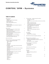
4. Hardware installation
The instrument air conditioning unit includes a stainless steel
ground plate, compressed air lters, automatic condensate sep-
arator and a membrane air dryer.
Steps
1. Place and attach the ground plate close to the measuring de-
vice using 8 dened xing holes, see “Dimensional Drawing”.
2. Connect the instrument air tube (10 mm) to the instrument air
inlet (1).
3. Connect the instrument air tube (10 mm) from the measuring
device (5) to the instrument air outlet (2).
1. Instrument air inlet
2. Instrument air outlet
3. Filter DFM-S 0070 OS
4. Filter DF-T 0050 OS
5. Measuring device:
instrument air inlet
Fig. 1: Connection overview: conditioning of instrument air
5. Electrical installation
The instrument air conditioning unit has to be fed with a
power supply of 95 … 240 V AC/±10% (50 … 60 Hz) or
100 … 125 V DC/±10%; refer to the user manual for Ultramat
UFM-D05.
Warning: Risk of death by electric shock
Risk of electric shock when working on electrical parts while
the unit is switched on.
b Before any action step ensure that the unit is turned o.
b A voltage separator (e. g. power plug or switch) must be pro-
vided close-by to separate all current carrying conductors.
5.1 Connections
Connect power supply
1. Check the supply voltage on the type plate of the condensate
separator UFM-D05 (left side; 1) to ensure the correct speci-
cations.
2. Loosen the screws (2) and remove the upper cover (3).
3. Unscrew the right threaded cable gland (4) and, if available
remove the plug and put through the cable (5).
4. Connect the power supply cable wires (5) to the terminal X1.
noco
nc
X2.3
321
X2
X2.1X2.2
X1.1X1.2
L(+)
N(–)
2
1
X1
X3.2X3.1
gnd
In1
2
1
X3
1. Condensate separator UFM-D05
2. Screw
3. Upper cover
4. Cable gland
5. Cable
Fig. 2: Electrical connections; see also terminal assignment
Connect fault indication and external test
Notice:
b Ensure a sucient clearance to other parts of the unit, or
suitable insulation.
5. Unscrew the left threaded cable gland (4) and, if available
remove the plug and put through the cable (5).
6. Connect the cable wires (5) to the terminal X2 and/or X3.
7. Tighten the threaded cable gland (4) slightly.
8. Put on the upper cover (3) and tighten the screws (2).
Terminal assignment
Terminal assignment for supply voltage (operating voltage)
Terminal X1 Terminal X2 Terminal X3
X1.1 X1.2 X2.1 X2.2 X2.3 X3.1 X3.2
L1 (+) N (–) NO CO NC IN1 GND
Phase Neutral Normally
open
Common Normally
closed
External
test
GND
Terminal assignment for potential-free contact and external test
Terminal X1 Terminal X2 Terminal X3
X1.1 X1.2 X2.1 X2.2 X2.3 X3.1 X3.2
L1 (+) N (–) NO CO NC IN1 GND
Power Neutral Normally
open
Common Normally
closed
External test GND
n.c.: Malfunction or power failure
n.o.: Normal operation
Potential-free contacts
Contacts closed: test active
Contacts open: test inac-
tive, no pot.-free contacts

Instrument Air Conditioning Unit | SICK8024118/V1-0/2019-03/en 2
6. Insert the new lter element (6)
to the marking (5) on the lter
bowl.
7. Grease the sealing rings at the
lter element (7) as shown.
Grease
8. Check marker at the lter top (8).
9. Grease the new lter bowl o-ring
on the lter top (9) and attach
the UFM-D05 housing.
10. Check that the nal position of
the lter housing is locked (ß).
Grease
7.3 Replacing the UFM-D05 maintenance kit
1. Remove UFM-D05 (2) by pressing
the arresting hook (1).
2. Unfasten UFM-D05 from the
outlet (5) and remove the design
shell (4).
3. Detach the maintenance unit (6)
from the tubing at the inlet by
removing the union nut.
4. Install the new maintenance unit
(6) in reverse order.
7.4 Replacing the lter element DF-T 0050 OS
1. Loosen and remove lower part
(bowl) of the lter housing (1).
2. Remove the lter element (2).
3. Insert the new lter element (4)
to the marking (3) on the lter
bowl.
4. Grease the sealing rings at the
lter element (5) as shown.
Grease
8. Specications
Instrument air specications
Particle (class 6/ISO 8573:2010) ≤ 100.000 solid particle [1 ... 5 µm]
Water vapor (class 4/ ISO 8573:2010) ≤ +3 °C pressure dew point (steam)
Total oil portion (class X/ ISO 8573:2010) ≤ 10 mg total oil (liquid, aerosol, fog)
Flow rate 1.3 Nm
3
/h
Pressure 12.5 bar
Operating temperature 1 ... 60 °C
Volume 1.5 l
8.1 Dimensional drawing
196 (7.72)
465 (18.31)
9 (0.35)
7 (0.28)
543 (21.38)
400 (15.75)
151 (5.94)
125 (4.92) 125 (4.92)125 (4.92)
6. Commissioning
b Before connecting the instrument air, blow the instrument air
into the environment for a few minutes. Check dryness with a
paper towel.
b Slowly apply pressure to the instrument air inlet. For the maxi-
mum limit value refer to “Specications”.
b Make sure that no pressure peaks occur. See manufacturer’s
documents attached.
7. Maintenance
7.1 Yearly maintenance work
Only the replacement of the lter elements of the maintenance
kit has to be carried out once a year.
Requirements: maintenance kit, part No. 5339994.
The maintenance kit consists of the components:
• Filter element DFM-S 0070 and housing sealing
• Maintenance kit for condensate separator UFM-D05 and
sealing
• Filter element DF-T 0050 and housing sealing
Overview of maintenance kits elements
1. Condensate separator UFM-D05
2. Filter DFM-S 0070 OS
3. Filter element DFM-S 0070 OS
4. Filter element DF-T 0050 OS
5. Filter DF-T 0050 OS
Fig. 3: Disassembly/assembly of maintenance kits components
Warning: Risk of death by electric shock
Risk of electric shock when working on electrical parts while
the unit is switched on.
b Before any action step ensure that the unit is turned o.
Caution: Risk of injury due to high pressure
When working on parts under pressure, it is possible that
parts come o unexpectedly or compressed air escapes.
b Before working on the unit, ensure an appropriate decom-
pression within the instrument air tubes.
7.2 Replacing the lter element DFM-S 0070 OU
1. Slowly reduce and stop the pressure supply at the instrument
air inlet.
2. Remove the UFM-D05 (2) by
pressing the arresting hook (1).
3. Reset UFM-D05: press the TEST
button (3) below the LED, hold it
for at least 5 sec. and switch o
the voltage supply.
4. Loosen and remove the lower part
(bowl) of the lter housing (3).
5. Remove the lter element (4).
/