Aiphone IX Series Owners & Installation Manual

Type
Owners & Installation Manual

Aiphone IX Series is a Networked Video Intercom System that seamlessly integrates audio, video, and door control, providing enhanced security and communication for residential and commercial properties. With its high-resolution camera, users can clearly see and speak with visitors at their door, while the door release feature allows for convenient access control. The system's microSD card slot enables local recording of video and images, adding an extra layer of security.

Aiphone IX Series is a Networked Video Intercom System that seamlessly integrates audio, video, and door control, providing enhanced security and communication for residential and commercial properties. With its high-resolution camera, users can clearly see and speak with visitors at their door, while the door release feature allows for convenient access control. The system's microSD card slot enables local recording of video and images, adding an extra layer of security.

Installation Manual
IX Series
Networked Video Intercom System
IX-DV, IX-DVF, IX-DVF-P, IX-DVF-2RA, IX-DVF-RA, IX-DVF-L,
IX-SSA, IX-SSA-2RA, IX-SSA-RA
Introduction
Read this manual before installation and connection. Read the "Setting Manual" and "Operation Manual". The manuals
can be downloaded from our homepage at “
https://www.aiphone.net/support/software-document/” free of charge.
After completing installation and connection, program the system according to the "Setting Manual". The system cannot
operate unless it is programmed.
After performing installation, review with the customer how to operate system. Leave documentation accompanying the
Master Station with the customer.
Perform installation and connection only after gaining sufficient understanding of the system and this manual.
The illustrations used in this manual may differ from the actual stations.
- 1 -
Literature information
The important information concerning correct operation and what you should observe is marked with the following
symbols.
Precautions
This symbol means that operating the device incorrectly or ignoring these precautions may
cause severe injury or death.
This symbol means that operating the device incorrectly or ignoring these precautions may
cause severe injury or property damage.
This symbol is intended to alert the user to prohibited actions.
This symbol is intended to alert the user to important instructions.
Warning
Negligence could result in death or serious injury.
Do not disassemble or modify the device.
May cause fire or electrical shock.
Do not use with a power supply voltage
above the specified voltage.
May cause fire or electrical shock.
Do not install two power supplies in parallel
to single input.
Fire or damage to the unit could result.
Do not connect any terminal on the unit to
AC power line.
Fire or electric shock could result.
For power supply, use Aiphone power supply
model specified for use with system.
If non-specified product is used, fire or
mulfunction could result.
Do not, under any circumstances, open up the
device.
Voltage within some internal components may
cause electrical shock.
The device is not designed to explosion-proof
specifications. Do not install or use in an
oxygen room or other such locations filled
with volatile gases.
May cause fire or explosion.
Caution
Negligence could result in injury to people or damage to property.
Do not install or connect the device with the
power on.
May cause electrical shock or malfunction.
Do not turn on power without first checking
to make sure the wiring is correct and there
are no improperly terminated wires.
May cause fire or electrical shock.
Do not put your ear close to the speaker when
using the device.
May cause harm to the ear if a sudden loud noise
is emitted.
Warning
Caution
- 2 -
General Precautions
Install low-voltage lines at least 30cm (11") away from high-voltage lines (AC100V, 200V), especially inverter air conditioner
wiring. Failure to do so may result in interference or malfunction.
When installing or using the device, give consideration to the privacy rights of subjects, as it is the responsibility of the system
owner to post signs or warnings in accordance with local ordinances.
Notice
If the device is used in areas where there are business-use wireless devices such as a transceiver or mobile phones, it may
cause malfunction.
If the device is installed close to a light dimmer, an inverter electrical appliance or the remote control unit of a hot-water system
or floor-heating system, it may create interference and cause a malfunction.
If the device is installed in an area with an extremely strong electrical field, such as in the vicinity of a broadcasting station, it
may create interference and cause a malfunction.
If warm air from inside the room enters the unit, the internal and external temperature difference may cause condensation on
the camera. Plugging of cable holes and other gaps where warm air might enter is recommended for preventing condensation.
Precautions for mounting
If installed in the place where the sound is easy to echo, it may be difficult to hear the conversation with echoed sounds.
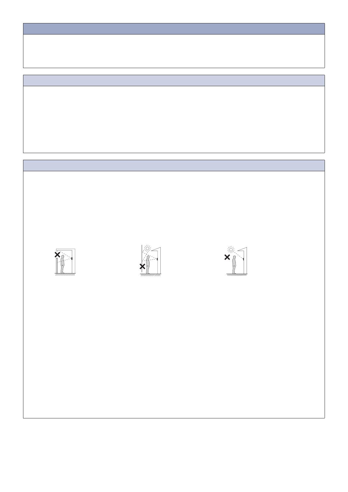
Installing the device in locations or positions such as the following may affect the clarity of the image:
Where lights will be shining directly into the camera at night time
Where the sky fills much of the background
Where the background of the subject is white
Where sunlight or other strong light sources will shine directly into the camera
In 50Hz regions, if a strong fluorescent light shines directly into the camera, it may cause the image to flicker. Either shield the
camera from the light or use an inverter fluorescent light.
Installing the device in the following locations could cause malfunction:
Locations that get hot
Close to a heater, boiler, etc.
Locations where there is risk of exposure to liquid, dust, oil, or chemicals
Locations with high humidity
Bathroom, basement, greenhouse, etc.
Locations with low temperature
Inside a cold storage warehouse, the front of a cooler, etc.
Locations directly exposed to steam or oil smoke
Next to heating devices or a cooking space, etc.
Sulphurous environments such as a hot spring area
Locations close to the sea or directly exposed to sea breeze
If existing wiring is used, the device may not operate properly. In that case, it will be necessary to replace the wiring.
Do not, under any circumstances, use an impact driver to fasten screws. Doing so may cause damage to the device.
Where the sky fills much of
the background
Where the background of
the subject is white
White
wall
Sky
Where sunlight or other strong light sources
will shine directly into the camera
- 3 -
Table of contents
Literature information ...................................................................................1
Precautions ..................................................................................................1
Example of System Configuration................................................................4
Part Names and Accessories.......................................................................5
Part Names .................................................................................................................. 5
Included accessories .................................................................................................... 8
IX-DV .............................................................................................................................................. 8
IX-DVF, IX-DVF-P, IX-DVF-2RA, IX-DVF-RA, IX-DVF-L, IX-SSA, IX-SSA-2RA, IX-SSA-RA ....... 8
Status Indicator ............................................................................................8
How to Install ...............................................................................................9
Video Door Station Installation ..................................................................................... 9
IX-DV (surface mount) ................................................................................................................... 9
IX-DVF, IX-DVF-P, IX-DVF-2RA, IX-DVF-RA, IX-DVF-L, IX-SSA, IX-SSA-2RA,
IX-SSA-RA (flush mount) ............................................................................................................. 10
Camera View Area and Mounting Location (IX-DV, IX-DVF, IX-DVF-P, IX-DVF-2RA,
IX-DVF-RA, IX-DVF-L) ............................................................................................... 11
Camera view adjustment .............................................................................................................. 11
Camera view range ...................................................................................................................... 11
How to Connect .........................................................................................12
Connection Precautions ............................................................................................. 12
Cat-5e/6 cable .............................................................................................................................. 12
Precautions regarding low-voltage line ........................................................................................ 12
Wiring Connection......................................................................................13
- 4 -
Example of System Configuration
LAN
PoE switch
(third party)
PC (third party)
PoE switch
(third party)
PoE switch
(third party)
Network video
recorder
(third party)
Network camera
(third party)
IX-DVFIX-DA
IX-MV
PoE switch
(third party)
PoE switch
(
third party
)
IXW-MA
PoE switch
(
third party
)
IX-SS-2G
IX-RS-BIX-MV7-HB
PoE switch
(third party)
- 5 -
Part Names and Accessories
Part Names
IX-DV
IX-DVF
IX-SSA
Under the Terminal cover
Moisture
drainage holes
Call Indicator
(Green)
Status indicator
(Orange/Blue)
Communication
Indicator (Orange)
Door release
Indicator (Green)
Speaker
Microphone
Camera
LED for night
illumination
Call button
Call Indicator
(Green)
Status indicator
(Orange/Blue)
Communication
Indicator (Orange)
Door release
Indicator (Green)
Speaker
Microphone
Camera
LED for night
illumination
Call button
Camera angle
adjustment lever
MAC address
Terminal cover
Reset button
microSD
card
eject button
Connectors
Camera angle
adjustment lever
MAC address
Terminal cover
Reset button
microSD
card
eject button
Connectors
LAN PoE PSE
Port (Out)
LAN PoE PD
Port (In)
microSD
card slot
Call Indicator
(Green)
Status indicator
(Orange/Blue)
Communication
Indicator (Orange)
Door release
Indicator (Green)
Speaker
Microphone
Call button
MAC address
Terminal cover
Reset button
microSD
card
eject button
Connectors
microSD
card slot
microSD
card slot
LAN PoE PSE
Port (Out)
LAN PoE PD
Port (In)
LAN PoE PSE
Port (Out)
LAN PoE PD
Port (In)
- 6 -
IX-DVF-2RA
IX-DVF-RA
IX-DVF-P
Call Indicator
(Green)
Status indicator
(Orange/Blue)
Communication
Indicator (Orange)
Door release
Indicator (Green)
Speaker
Braille
Microphone
Camera
LED for night
illumination
Call button
Call button
Camera angle
adjustment lever
MAC address
Terminal cover
Reset button
microSD
card
eject button
Connectors
LAN PoE PSE
Port (Out)
LAN PoE PD
Port (In)
microSD
card slot
Call Indicator
(Green)
Status indicator
(Orange/Blue)
Communication
Indicator (Orange)
Door release
Indicator (Green)
Speaker
Microphone
Camera
LED for night
illumination
Camera angle
adjustment lever
MAC address
Terminal cover
Reset button
microSD
card
eject button
Connectors
Emergency
call button
Emergency
call button
Braille
Call Indicator
(Green)
Status indicator
(Orange/Blue)
Communication
Indicator (Orange)
Door release
Indicator (Green)
Speaker
Microphone
Camera
LED for night
illumination
Camera angle
adjustment lever
MAC address
Terminal cover
Reset button
microSD
card
eject button
Connectors
Slot for HID
®
reader
(Please refer to the manufacturers specification for the details.)
Under the Terminal cover
microSD
card slot
microSD
card slot
LAN PoE PSE
Port (Out)
LAN PoE PD
Port (In)
LAN PoE PSE
Port (Out)
LAN PoE PD
Port (In)
- 7 -
IX-SSA-2RA
IX-SSA-RA
IX-DVF-L
Call Indicator
(Green)
Status indicator
(Orange/Blue)
Communication
Indicator (Orange)
Door release
Indicator (Green)
Speaker
Microphone
Camera
LED for night
illumination
Call button
Camera angle
adjustment lever
MAC address
Terminal cover
Hearing aid
unit
Reset button
microSD
card
eject button
Connectors
microSD
card slot
T-mode
hearing aid
indication
Name plate
(with backlight)
Call Indicator
(Green)
Status indicator
(Orange/Blue)
Communication
Indicator (Orange)
Door release
Indicator (Green)
Speaker
Microphone
Call button
MAC address
Terminal cover
Reset button
microSD
card
eject button
Connectors
microSD
card slot
Under the Terminal cover
Braille
Emergency
call button
Call Indicator
(Green)
Status indicator
(Orange/Blue)
Communication
Indicator (Orange)
Door release
Indicator (Green)
Speaker
Microphone
MAC address
Terminal cover
Reset button
microSD
card
eject button
Connectors
microSD
card slot
Braille
Emergency
call button
Setting switch*
ON
1 2
Switch setting
Output gain
1=OFF, 2=OFF
1=OFF, 2=ON
1=ON, 2=OFF
0 dB
-6 dB
-12 dB (Default setting)
1=ON, 2=ON
-14 dB
1=ON, 2=OFF
* Factory presetting
LAN PoE PSE
Port (Out)
LAN PoE PD
Port (In)
LAN PoE PSE
Port (Out)
LAN PoE PD
Port (In)
LAN PoE PSE
Port (Out)
LAN PoE PD
Port (In)
- 8 -
Included accessories
IX-DV
IX-DVF, IX-DVF-P, IX-DVF-2RA, IX-DVF-RA, IX-DVF-L, IX-SSA, IX-SSA-2RA, IX-SSA-RA
Status Indicator
Refer to "Operation Manual" for additional indicators not listed.
: Lit : Off
Anchors x 4 Wall-mounting screws x 4 Special screwdriver x 1
Installation Manual × 2 (English,
French)
Notice (IX Manuals and Software) x 1 Option connectors
(6pin x 1, 7pin x 1, 8pin x 1)
Ferrite cores x 2
Chinese RoHS declaration × 1
Back box x 1 Special screws x 4 Special screwdriver x 1
Installation Manual × 2 (English,
French)
Notice (IX Manuals and Software) x 1 Option connectors
(6pin x 1, 7pin x 1, 8pin x 1)
Ferrite cores x 2 Transparent name plates x 2
(IX-DVF-L only)
Chinese RoHS declaration × 1
Status (Pattern) Meaning
Orange flashing Normal flashing Booting
Rapid flashing Device error
Long interval flashing Communication failure
Long irregular flashing Firmware version updating
Long irregular flashing Mounting micro SD card,
unmounting micro SD card
Long irregular flashing Initializing
Blue light Standby
0.75 sec 0.75 sec
0.25 sec 0.25 sec
0.5 sec 4 sec
1
sec
0.25
sec
0.25
sec
0.25
sec
0.25
sec
0.25
sec
2
sec
0.25
sec
0.25
sec
0.25
sec
1
sec
0.25
sec
0.25
sec
0.25
sec
- 9 -
How to Install
Video Door Station Installation
IX-DV (surface mount)
The installation height of the equipment should not exceed more than 2m (Upper Edge) from the ground level.
1
4
5
2
Loosen the screw
with the special
screwdriver, and
remove the front
cover.
Loosen
Special
screwdriver
(included)
Vandal-resistant
front panel
Attach the front
cover to the unit by
hanging the upper
2 clips on the unit.
Tighten
Fasten the unit to the
mounting surface.
* Use anchors or concrete plugs
as needed.
Anchors (included) ×4
Option
connectors
(included)
Cat-5e/6 cable
Unit
Wall-mounting screws
(included) ×4
Open the terminal cover, and join
the option connectors (included) to
the low-voltage lines, and insert the
option connectors and Cat-5e/6
cable to the unit.
NOTE
Make room for threading a screw.
Screw mounting
hole ×4
Unit center
Unit
center
86.4 mm (3-3/8'')
60 mm (2-3/8")
30 mm (1-3/16")
182.6 mm (7-3/16'')
95 mm (3-3/4")
Ø 6 mm
(Ø 1/4")
35 mm
(1-3/8")
Moisture drainage holes ×3
Do not block the holes.
Recommended
Mounting height
1,500 mm (4' 11'')
(max.1,850mm (6' 3/4"))
(1) Slide the terminal cover down.
(2) Open up the terminal cover.
(3) Insert the option connectors and Cat-5e/6
cable to the unit, and replace the terminal
cover.
Low-voltage
lines
Clamp the ferrite cores to
Cat-5e/6 cables.
3
* Tighten the screw
with the cover
pressed to the wall.
Open the
ferrite core.
Thread
Cat-5e/6 cable
through the
ferrite core.
Option connectors
Ferrite cores (included) ×2
Cat-5e/6 cable
Option connectors
Cat-5e/6 cable
Be sure to close the terminal cover when
done. If left open, condensation or water
may enter, preventing heat dissipation and
causing damage.
- 10 -
IX-DVF, IX-DVF-P, IX-DVF-2RA, IX-DVF-RA, IX-DVF-L, IX-SSA, IX-SSA-2RA,
IX-SSA-RA (flush mount)
When installing the unit on a rough surface, please use sealant to seal the unit edges to prevent water entering the unit.
If the unit edges are left unsealed on a rough surface, IP65 ingress protection rating is not guaranteed.
ABCDEFG
5
1
4
2
3
Tighten
e.g.) IX-DVF-L
To insertion
opening
To insertion
opening
(1) Peel off the protective plastic on the plate
(both sides).
(2) Fill in the name on the transparent name plate.
· Be sure to leave 25 mm (1") of white space on the right end to account for insertion.
(3) Insert the filled-in transparent name plate at the specified insertion opening (indicated
with arrow to the right).
Install the back box in the wall.
Recommended Mounting height (box center)
1,500 mm (4'11'')
(max.1,850mm (6' 3/4"))
Insert the transparent name plate.
(IX-DVF-L only)
Loosen
Back box (included)
Vandal-resistant front panel with
the unit attached
148 mm *
(5-13/16'')
60 mm
(2-3/8
'')
267 mm **
(10-1/2
'')
Special screws (included) × 4
Special screwdriver
(included)
Fasten the front panel to the
back box with the special
screws.
Transparent name plate (included in IX-DVF-L only)
The back box must be installed at a depth of 5
mm (3/16
'') or more from the wall face.
Min.
5 mm (3/16
'')
Wall
Back box
* For IX-DVF and IX-SSA: 120 mm (4-3/4'')
** For IX-DVF and IX-SSA: 235 mm (9-1/4'')
Open the terminal cover, and join the option
connectors (included) to the low-voltage lines, and
insert the option connectors and Cat-5e/6 cable to
the unit.
(1) Slide the terminal cover down.
(2) Open up the terminal cover.
(3) Insert the option connectors and
Cat-5e/6 cable to the unit, and
replace the terminal cover.
Be sure to close the
terminal cover when done.
If left open, condensation
or water may enter,
preventing heat dissipation
and causing damage.
Option connectors
Cat-5e/6 cable
Clamp the ferrite cores to
Cat-5e/6 cables.
Open the
ferrite core.
Thread
Cat-5e/6 cable
through the
ferrite core.
Option connectors
Ferrite cores (included) ×2
Cat-5e/6 cable
Option connectors (included)
Low-voltage lines
25 mm (1")
2 mm (1/8
")
- 11 -
Camera View Area and Mounting Location (IX-DV, IX-DVF, IX-DVF-P,
IX-DVF-2RA, IX-DVF-RA, IX-DVF-L)
Camera view adjustment
Camera view range
The camera range as illustrated is only an approximate indication and may vary according to the environment.
IX-DV, IX-DVF
IX-DVF-P, IX-DVF-2RA, IX-DVF-RA, IX-DVF-L
When light enters the camera, the monitor screen may flicker brightly or the subject may become dark. Try to prevent
strong lighting from entering the camera directly.
Using the camera angle adjustment lever, the camera can be
tilted up or down (-8°, 0°, +13°). Adjust the camera to the
optimal position.
Back View
Camera angle adjustment lever
- 8°
+ 13°
Vertical
Camera angle 0° Camera angle 13° Camera angle -8°
1,900 mm (6' 2'')
1,200 mm (3' 11'')
700 mm (2' 3'')
500 mm
(1' 7'')
Center
of device
Center
of device
Center
of device
The dimensions are approximate in this page.
1,500 mm
(4' 11'')
1,400 mm
(4' 7'')
750 mm (2' 5'')
2,150 mm (7')
500 mm
(1' 7'')
1,500 mm
(4' 11'')
1,800 mm (5' 10'')
1,100 mm (3' 7'')
700 mm (2' 3'')
500 mm
(1' 7'')
1,500 mm
(4' 11'')
Horizontal
(When the object position is lowered due to a
stepped floor, etc.)
1,150 mm (3' 9'')
500 mm
(1' 7'')
Vertical
Camera angle 0° Camera angle 13° Camera angle -8°
1,950 mm (6' 4'')
1,250 mm (4' 1'')
700 mm (2' 3'')
500 mm
(1' 7'')
The dimensions are approximate in this page.
1,500 mm
(4' 11'')
1,400 mm
(4' 7'')
750 mm (2' 5'')
2,150 mm (7')
500 mm
(1' 7'')
1,500 mm
(4' 11'')
1,800 mm (5' 10'')
1,100 mm (3' 7'')
700 mm (2' 3'')
500 mm
(1' 7'')
1,500 mm
(4' 11'')
Horizontal
(When the object position is lowered due to a
stepped floor, etc.)
1,150 mm (3' 9'')
500 mm
(1' 7'')
Center
of device
Center
of device
Center
of device
- 12 -
How to Connect
Connection Precautions
Cat-5e/6 cable
For connection between devices, use a straight-through cable.
If necessary, when bending the cable, please observe the manufacturer's recommendations. Failure to do so could cause a
communication failure.
Do not strip away the cable insulation any more than is necessary.
Perform termination in accordance with TIA/EIA-568A or 568B.
Before connecting the cable, be sure to verify conduction using a LAN checker or similar tool.
A RJ45 covered connector cannot be connected to the LAN ports of the master stations or the door stations. Use cables without
covers on the connectors.
Be careful not to pull on the cable or subject it to excessive stress.
Precautions regarding low-voltage line
Use PE (polyethylene)-insulated PVC jacketed cable. Parallel or jacketed conductors, mid-capacitance, nonshielded cable is
recommended.
Never use twisted-pair cable or coaxial cable.
2Pr quad V twisted pair cables cannot be used.
When connecting low-voltage lines, perform the connection using either the crimp sleeve method or soldering, then insulate the
connection with electrical tape.
If the connector-attached lead wire is too short, extend the lead with an intermediate connection.
As the connector has polarity, perform the connection correctly. If the polarity is incorrect, the device will not operate.
When using the crimp sleeve method, if the end of the connector-attached lead wire has been soldered, first cut off the
soldered part and then perform crimp.
After completing connection of wires, check that there are no breaks or inadequate connections. When
connecting low-voltage lines in particular, perform the connection using either soldering or the crimp sleeve
method and then insulate the connection with electrical tape. For optimal performance, keep the number of
wiring connections to a minimum.
Simply twisting low-voltage lines together will create poor contact or will lead to oxidization of the surface of the low-
voltage lines over long-term use, causing poor contact and resulting in the device malfunctioning or failure.
Coaxial cableParallel cable
Crimp terminal
Solid
wire
Stranded
wire
Solid
wire
Stranded
wire
Electrical tape
Soldering
Electrical tape
Line up the solid wire
and stranded wire and
crimp them together.
1.
Overlap the tape by at
least a half width and
wrap the connection at
least twice.
2.
Twist the stranded
wire around the solid
wire at least 3 times.
1.
After bending down the
point, perform soldering,
with care that no wires
protrude from the
soldering.
2.
Overlap the tape by at
least a half width and
wrap the connection
at least twice.
3.
Crimp sleeve method Soldering method
Soldering method Crimp sleeve method
- 13 -
Wiring Connection
Insulate and secure unused low-voltage lines and the connector-attached lead wire.
S1 S2 S3 S4 S5 SE
NO1 COM1 NC1 NO2 COM2 NC2
IX-DVFIX-DV IX-SSA, etc
Door Stations
CN1
CN2
+
P
P
S6ES6
CN3
Brown
Red
Orange
Yellow
Green
Blue
Brown
Red
Orange
Yellow
Green
Blue
Brown
Red
Orange
Yellow
Green
Blue
CN4 CN5
24VDC
(AC Power adapter PS-2420)
Pre-installed Emergency button Pre-installed Hearing aid unit
(IX-DVF-L)
(IX-DVF-RA, IX-SSA-RA,
IX-DVF-2RA, IX-SSA-2RA)
- 14 -
LAN PoE PSE
LAN PoE PD
IEEE802.3af/at
Cat-5e/6 straight
IEEE802.3af
Cat-5e/6 straight
100m (330')
100m (330')
LAN PoE PSE *
4
LAN PoE PD (works only with LAN PoE PSE(IEEE802.3at)switch)
PE0.8(20AWG)-2C
PE0.8(20AWG)-2C
PE0.8(20AWG)-2C
PE0.8(20AWG)-2C
PE0.8(20AWG)-2C
15m (49')
15m (49')
Additional IP device
PoE switch
Contact Input 6 *¹
(IX-DV, IX-DVF, IX-DVF-P and
IX-SSA)
Audio Output *²
(to paging amplifier)
24 VDC
(AC Power adapter PS-2420) *
4
Non Polarized
Contact Input 1 to 5 *¹
Relay Output 1 *³
Relay Output 2 *³
- 15 -
*1 Contact Input Specifications
*2 Audio Output Specifications
*3 Relay Output Specifications
*4 The intercom unit can be powered by using a PoE switch or Aiphone PS-2420 power supply. In the case "PoE
PSE" output of the intercom unit is used to power other devices, IEEE802.3at compatible PoE switch must be used to
power the intercom unit.
In the case both a PoE switch and Aiphone PS-2420 power supply are used in combination to power the intercom
unit,PS-2420 can provide back-up power if the PoE power supply fails. this allows continuous recording function etc.
to continue operating.
Input method Programmable dry contact (N/O or N/C)
Level detection method
Detection time 100 msec or more
Contact resistance Make: 700 Ω or less
Break: 3 kΩ or more
Terminal short-circuit current 20 mA or less
Voltage between terminals 5 VDC or less (between open terminals)
Output impedance 600 Ω
Output audio level 300 mVrms (with 600 Ω termination)
Output method Form C dry contact (N/O or N/C)
Contact rating 24 VAC, 1 A (resistive load)
24 VDC, 1 A (resistive load)
Minimum overload (AC/DC): 100mV, 0.1mA
https://www.aiphone.net/
AIPHONE CO., LTD., NAGOYA, JAPAN
Issue Date: Feb.2019 FK2452 P0219 RQ 61265
  • Page 1 1
  • Page 2 2
  • Page 3 3
  • Page 4 4
  • Page 5 5
  • Page 6 6
  • Page 7 7
  • Page 8 8
  • Page 9 9
  • Page 10 10
  • Page 11 11
  • Page 12 12
  • Page 13 13
  • Page 14 14
  • Page 15 15
  • Page 16 16

Aiphone IX Series Owners & Installation Manual

Type
Owners & Installation Manual

Aiphone IX Series is a Networked Video Intercom System that seamlessly integrates audio, video, and door control, providing enhanced security and communication for residential and commercial properties. With its high-resolution camera, users can clearly see and speak with visitors at their door, while the door release feature allows for convenient access control. The system's microSD card slot enables local recording of video and images, adding an extra layer of security.

Ask a question and I''ll find the answer in the document

Finding information in a document is now easier with AI