Page is loading ...

Documentation
BK11x0, BK1250
EtherCAT Bus Coupler
4.1
25.04.2017
Version:
Date:


Table of contents
BK11x0, BK12504 Version: 4.1
Table of contents
1 Product overview - EtherCAT Bus Coupler ............................................................................................3
2 Foreword ....................................................................................................................................................7
2.1 Notes on the documentation........................................................................................................... 7
2.2 Safety instructions .......................................................................................................................... 8
2.3 Documentation issue status............................................................................................................ 9
2.4 Version identification of EtherCAT devices..................................................................................... 9
3 Product overview.....................................................................................................................................14
3.1 Introduction ................................................................................................................................... 14
3.2 Technical data .............................................................................................................................. 16
4 Basic principles .......................................................................................................................................17
4.1 System properties......................................................................................................................... 17
4.2 The Beckhoff Bus Terminal system .............................................................................................. 20
4.3 CoE Interface................................................................................................................................ 21
4.4 EtherCAT State Machine .............................................................................................................. 25
4.5 LEDs and connection.................................................................................................................... 28
4.5.1 LEDs ................................................................................................................................28
4.5.2 Connection BK1120 and BK1150 ....................................................................................32
4.5.3 Connection BK1250 .........................................................................................................33
5 Mounting and wiring ...............................................................................................................................34
5.1 Instructions for ESD protection ..................................................................................................... 34
5.2 Installation on mounting rails ........................................................................................................ 35
5.3 Installation instructions for enhanced mechanical load capacity .................................................. 38
5.4 Installation positions ..................................................................................................................... 39
5.5 Power supply, potential groups..................................................................................................... 40
5.6 Ethernet cable............................................................................................................................... 41
5.7 EtherCAT wiring............................................................................................................................ 43
5.8 ATEX - Special conditions (extended temperature range) ........................................................... 44
5.9 ATEX Documentation ................................................................................................................... 45
6 Parameterization and commissioning...................................................................................................46
6.1 Start-up behavior of the Bus Coupler ........................................................................................... 46
6.2 EKxxxx - Optional Distributed Clocks support .............................................................................. 46
6.3 KL register communication ........................................................................................................... 48
6.3.1 Parameterization of KL terminals.....................................................................................48
6.3.2 Configuration of KL terminals via EtherCAT ....................................................................50
6.3.3 Online parameterization of KL terminals via CoE ............................................................53
6.3.4 Online parameterization of KL terminals via AoE ............................................................55
6.3.5 Beckhoff coupler tables....................................................................................................56
6.4 TwinCAT System Manager........................................................................................................... 58
6.4.1 BK1120, BK1150 - configuration overview ......................................................................58
6.4.2 BK1250 - configuration overview .....................................................................................59
6.4.3 Inputs - configuration overview ........................................................................................60
6.4.4 Outputs - configuration overview .....................................................................................60
6.4.5 Status of the working counter (Wc state) - - configuration overview................................61
6.4.6 Online status (info data) - configuration overview............................................................62
6.4.7 ADS address (ADSAddr) - configuration overview ..........................................................63
6.4.8 EtherCAT cycle time - configuration overview .................................................................64

Table of contents
BK11x0, BK1250 5Version: 4.1
6.4.9 Object description ............................................................................................................64
6.4.10 Mapping the Bus Terminals .............................................................................................74
6.4.11 Process image example...................................................................................................75
6.5 KS2000 configuration software..................................................................................................... 76
6.5.1 Example: parameterization with the KS2000 configuration software...............................76
7 Error handling and diagnosis.................................................................................................................80
7.1 Error messages to the EtherCAT master...................................................................................... 80
8 Appendix ..................................................................................................................................................81
8.1 General operating conditions........................................................................................................ 81
8.2 ATEX Documentation ................................................................................................................... 82
8.3 UL notice....................................................................................................................................... 82
8.4 Test standards for device testing.................................................................................................. 84
8.5 Firmware compatibility .................................................................................................................. 85
8.6 Support and Service ..................................................................................................................... 86

Table of contents
BK11x0, BK12506 Version: 4.1

Foreword
BK11x0, BK1250 7Version: 4.1
2 Foreword
2.1 Notes on the documentation
Intended audience
This description is only intended for the use of trained specialists in control and automation engineering who
are familiar with the applicable national standards.
It is essential that the documentation and the following notes and explanations are followed when installing
and commissioning these components.
It is the duty of the technical personnel to use the documentation published at the respective time of each
installation and commissioning.
The responsible staff must ensure that the application or use of the products described satisfy all the
requirements for safety, including all the relevant laws, regulations, guidelines and standards.
Disclaimer
The documentation has been prepared with care. The products described are, however, constantly under
development.
We reserve the right to revise and change the documentation at any time and without prior announcement.
No claims for the modification of products that have already been supplied may be made on the basis of the
data, diagrams and descriptions in this documentation.
Trademarks
Beckhoff
®
, TwinCAT
®
, EtherCAT
®
, Safety over EtherCAT
®
, TwinSAFE
®
, XFC
®
and XTS
®
are registered
trademarks of and licensed by Beckhoff Automation GmbH.
Other designations used in this publication may be trademarks whose use by third parties for their own
purposes could violate the rights of the owners.
Patent Pending
The EtherCAT Technology is covered, including but not limited to the following patent applications and
patents: EP1590927, EP1789857, DE102004044764, DE102007017835 with corresponding applications or
registrations in various other countries.
The TwinCAT Technology is covered, including but not limited to the following patent applications and
patents: EP0851348, US6167425 with corresponding applications or registrations in various other countries.
EtherCAT
®
is registered trademark and patented technology, licensed by Beckhoff Automation GmbH,
Germany
Copyright
© Beckhoff Automation GmbH & Co. KG, Germany.
The reproduction, distribution and utilization of this document as well as the communication of its contents to
others without express authorization are prohibited.
Offenders will be held liable for the payment of damages. All rights reserved in the event of the grant of a
patent, utility model or design.

Foreword
BK11x0, BK12508 Version: 4.1
2.2 Safety instructions
Safety regulations
Please note the following safety instructions and explanations!
Product-specific safety instructions can be found on following pages or in the areas mounting, wiring,
commissioning etc.
Exclusion of liability
All the components are supplied in particular hardware and software configurations appropriate for the
application. Modifications to hardware or software configurations other than those described in the
documentation are not permitted, and nullify the liability of Beckhoff Automation GmbH & Co. KG.
Personnel qualification
This description is only intended for trained specialists in control, automation and drive engineering who are
familiar with the applicable national standards.
Description of symbols
In this documentation the following symbols are used with an accompanying safety instruction or note. The
safety instructions must be read carefully and followed without fail!
DANGER
Serious risk of injury!
Failure to follow the safety instructions associated with this symbol directly endangers the
life and health of persons.
WARNING
Risk of injury!
Failure to follow the safety instructions associated with this symbol endangers the life and
health of persons.
CAUTION
Personal injuries!
Failure to follow the safety instructions associated with this symbol can lead to injuries to
persons.
Attention
Damage to the environment or devices
Failure to follow the instructions associated with this symbol can lead to damage to the en-
vironment or equipment.
Note
Tip or pointer
This symbol indicates information that contributes to better understanding.

Foreword
BK11x0, BK1250 9Version: 4.1
2.3 Documentation issue status
Version Modifications
4.1 • Update chapter "Notes on the documentation"
• Update chapter "Technical data"
• Addenda chapter "Instructions for ESD protection"
• Chapter "ATEX - Special conditions" replaced with chapter
"ATEX - Special conditions (extended temperature range)"
• Update chapter "General operating conditions"
• Update revision status
4.0 • Migration
• Update structure
• Update revision status
3.0 • Update structure
• Notes regarding ET
2.9 • Note re status bits amended
2.8 • Update Technical data
2.7 • Addenda technical notes
2.6 • Update Technical data
2.5 • BK1150 added
2.4 • Extension of terminal diagnostics
2.3 • Correction Diagnostic LEDs
2.2 • CoE access, AoE
2.1 • Object descriptions amended
2.0 • BK1250 added; object descriptions and technical data
amended
1.0 • Object descriptions amended
0.2 • Technical data added
0.1 • First preliminary version
2.4 Version identification of EtherCAT devices
Designation
A Beckhoff EtherCAT device has a 14-digit designation, made up of
• family key
• type
• version
• revision
Example Family Type Version Revision
EL3314-0000-0016 EL terminal
(12 mm, non-
pluggable connection
level)
3314 (4-channel thermocouple
terminal)
0000 (basic type) 0016
ES3602-0010-0017 ES terminal
(12 mm, pluggable
connection level)
3602 (2-channel voltage
measurement)
0010 (high-
precision version)
0017
CU2008-0000-0000 CU device 2008 (8-port fast ethernet switch) 0000 (basic type) 0000

Foreword
BK11x0, BK125010 Version: 4.1
Notes
• The elements mentioned above result in the technical designation. EL3314-0000-0016 is used in the
example below.
• EL3314-0000 is the order identifier, in the case of “-0000” usually abbreviated to EL3314. “-0016” is the
EtherCAT revision.
• The order identifier is made up of
- family key (EL, EP, CU, ES, KL, CX, etc.)
- type (3314)
- version (-0000)
• The revision -0016 shows the technical progress, such as the extension of features with regard to the
EtherCAT communication, and is managed by Beckhoff.
In principle, a device with a higher revision can replace a device with a lower revision, unless specified
otherwise, e.g. in the documentation.
Associated and synonymous with each revision there is usually a description (ESI, EtherCAT Slave
Information) in the form of an XML file, which is available for download from the Beckhoff web site.
From 2014/01 the revision is shown on the outside of the IP20 terminals, see Fig. “EL5021 EL terminal,
standard IP20 IO device with batch number and revision ID (since 2014/01)”.
• The type, version and revision are read as decimal numbers, even if they are technically saved in
hexadecimal.
Identification number
Beckhoff EtherCAT devices from the different lines have different kinds of identification numbers:
Production lot/batch number/serial number/date code/D number
The serial number for Beckhoff IO devices is usually the 8-digit number printed on the device or on a sticker.
The serial number indicates the configuration in delivery state and therefore refers to a whole production
batch, without distinguishing the individual modules of a batch.
Structure of the serial number: KKYYFFHH
KK - week of production (CW, calendar week)
YY - year of production
FF - firmware version
HH - hardware version
Example with
Ser. no.: 12063A02: 12 - production week 12 06 - production year 2006 3A - firmware version 3A 02 -
hardware version 02
Exceptions can occur in the IP67 area, where the following syntax can be used (see respective device
documentation):
Syntax: D ww yy x y z u
D - prefix designation
ww - calendar week
yy - year
x - firmware version of the bus PCB
y - hardware version of the bus PCB
z - firmware version of the I/O PCB
u - hardware version of the I/O PCB
Example: D.22081501 calendar week 22 of the year 2008 firmware version of bus PCB: 1 hardware version
of bus PCB: 5 firmware version of I/O PCB: 0 (no firmware necessary for this PCB) hardware version of I/O
PCB: 1
Unique serial number/ID, ID number
In addition, in some series each individual module has its own unique serial number.
See also the further documentation in the area

Foreword
BK11x0, BK1250 11Version: 4.1
• IP67: EtherCAT Box
• Safety: TwinSafe
• Terminals with factory calibration certificate and other measuring terminals
Examples of markings
Fig.1: EL5021 EL terminal, standard IP20 IO device with batch number and revision ID (since 2014/01)
Fig.2: EK1100 EtherCAT coupler, standard IP20 IO device with batch number
Fig.3: CU2016 switch with batch number

Foreword
BK11x0, BK125012 Version: 4.1
Fig.4: EL3202-0020 with batch numbers 26131006 and unique ID-number 204418
Fig.5: EP1258-00001 IP67 EtherCAT Box with batch number 22090101 and unique serial number 158102
Fig.6: EP1908-0002 IP76 EtherCAT Safety Box with batch number 071201FF and unique serial number
00346070
Fig.7: EL2904 IP20 safety terminal with batch number/date code 50110302 and unique serial number
00331701

Foreword
BK11x0, BK1250 13Version: 4.1
Fig.8: ELM3604-0002 terminal with ID number (QR code) 100001051 and unique serial number 44160201

Product overview
BK11x0, BK125014 Version: 4.1
3 Product overview
3.1 Introduction
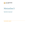
EtherCAT coupler for K-bus Terminals
BK1120, BK1150
Fig.9: Bus Couplers BK1120 and BK1150
The Bus Couplers BK1120 and BK1150 connect EtherCAT with the tried and tested Beckhoff K-bus
terminals (KLxxx). A station consists of a BK1120 / BK1150 Bus Coupler, any number of K-bus terminals (up
to 64, or up to 255 with K-bus extension) and a bus end terminal. The Bus Coupler recognizes the connected
terminals and automatically allocates them into the EtherCAT process image. The Bus Coupler is connected
to the network via the upper Ethernet interface. The lower RJ45 socket may be used to connect further
EtherCAT devices in the same segment. In the EtherCAT network, the BK1120 / BK1150 Bus Coupler can
be installed anywhere in the Ethernet signal transfer section (100BASE-TX) – except directly at the switch.
The Bus Couplers BK9000 (for K-bus terminals) and EK1000 (for E-bus terminals) are suitable for
application at the switch.

Product overview
BK11x0, BK1250 15Version: 4.1
BK1250
Fig.10: BK1250
Fig.11: K-bus_E-bus
The BK1250 is a "Bus Coupler in the terminal housing" for mixed application of EtherCAT terminals (ELxxxx)
and standard Bus Terminals (KLxxxx) in a bus station. It allows implementation of compact and cost-effective
control solutions. The wide range of more than 300 available Bus Terminals (incl. special terminals) can thus
be optimally combined with the communication speed and large bandwidth of EtherCAT terminals. Up to 64
Bus Terminals (with K-bus extension up to 255) can be connected to a BK1250. The Bus Coupler recognizes
the connected Bus Terminals and automatically allocates them into the EtherCAT process image.

Product overview
BK11x0, BK125016 Version: 4.1
3.2 Technical data
Technical data BK1120 BK1150 BK1250
Task in the EtherCAT system Coupling of standard Bus Terminals (KLxxxx) to 100BASE-TX EtherCAT
networks
Number of K-bus terminals 64 (255 with K-bus extension interface KL9020 and KL9050)
Max. number of bytes,
fieldbus
1024bytes input and 1024bytes output
Digital peripheral signals 8192 inputs/outputs
Analog peripheral signals 256 inputs/outputs
Protocols EtherCAT
Baud rate 100Mbaud
Configuration KS2000 configuration software, TwinCAT System Manager or via EtherCAT
(ADS)
Bus connection 2 x RJ45 via E-bus contacts
Power supply 24V
DC
(-15%/+20%)
Current consumption 70mA + (K-bus current)/4, max. 500mA 70mA + (K-bus current)/4,
max. 200mA
K-bus power supply (5 V) max. 1750mA max. 2000mA max. 500mA
Power contacts max. 24V
DC
, max. 10A
Electrical isolation 500V (power contact/supply voltage/Ethernet)
Weight approx. 170g approx. 55g
Permissible ambient
temperature range during
operation
-25°C ... +60°C (extended temperature range)
Permissible ambient
temperature range during
storage
-40°C ... + 85°C
Permissible relative humidity 95%, no condensation
Dimensions (W x H x D) approx. 49mm x 100mm x 70mm approx. 15mm x 100mm x
70mm (width aligned: 12mm)
Mounting on 35mm mounting rail conforms to EN 60715
Vibration/shock resistance conforms to EN 60068-2-6 / EN 60068-2-27,
see also installation instructions for enhanced mechanical load capacity
[}38]
EMC immunity/emission conforms to EN 61000-6-2 / EN 61000-6-4
Protection class IP20
Installation position variable
Approval CE
ATEX [}44]
cULus [}82]

Basic principles
BK11x0, BK1250 17Version: 4.1
4 Basic principles
4.1 System properties
Protocol
The EtherCAT protocol is optimized for process data and is transported directly within the Ethernet frame
thanks to a special Ether-type. It may consist of several sub-telegrams, each serving a particular memory
area of the logical process images that can be up to 4 gigabytes in size. The data sequence is independent
of the physical order of the Ethernet terminals in the network; addressing can be in any order. Broadcast,
Multicast and communication between slaves are possible. Transfer directly in the Ethernet frame is used in
cases where EtherCAT components are operated in the same subnet as the control computer.
However, EtherCAT applications are not limited to a subnet: EtherCAT UDP packs the EtherCAT protocol
into UDP/IP datagrams. This enables any control with Ethernet protocol stack to address EtherCAT systems.
Even communication across routers into other subnets is possible. In this variant, system performance
obviously depends on the real-time characteristics of the control and its Ethernet protocol implementation.
The response times of the EtherCAT network itself are hardly restricted at all: the UDP datagram only has to
be unpacked in the first station.
Fig.12: EtherCAT Telegram Structure
Protocol structure: The process image allocation is freely configurable. Data are copied directly in the I/O
terminal to the desired location within the process image: no additional mapping is required. The available
logical address space is with very large (4 GB).

Basic principles
BK11x0, BK125018 Version: 4.1
Topology
Line, tree or star: EtherCAT supports almost any topology. The bus or line structure known from the
fieldbuses thus also becomes available for Ethernet. Particularly useful for system wiring is the combination
of line and junctions or stubs. The required interfaces exist on the couplers; no additional switches are
required. Naturally, the classic switch-based Ethernet star topology can also be used.
Fig.13: EtherCAT Topology
Maximum wiring flexibility:
with or without switch, line or tree topologies, can be freely selected and combined.
Wiring flexibility is further maximized through the choice of different cables. Flexible and cost-effective
standard Ethernet patch cables transfer the signals in Ethernet mode (100Base-TX). The complete
bandwidth of the Ethernet network - such as different optical fibers and copper cables - can be used in
combination with switches or media converters.
Distributed Clocks
Accurate synchronization is particularly important in cases where spatially distributed processes require
simultaneous actions. This may be the case, for example, in applications where several servo axes carry out
coordinated movements simultaneously.
The most powerful approach for synchronization is the accurate alignment of distributed clocks, as described
in the new IEEE 1588 standard. In contrast to fully synchronous communication, where synchronization
quality suffers immediately in the event of a communication fault, distributed aligned clocks have a high
degree of tolerance vis-à-vis possible fault-related delays within the communication system.

Basic principles
BK11x0, BK1250 19Version: 4.1
With EtherCAT, the data exchange is fully based on a pure hardware machine. Since the communication
utilizes a logical (and thanks to full-duplex Fast Ethernet also physical) ring structure, the mother clock can
determine the run-time offset to the individual daughter clocks simply and accurately - and vice versa. The
distributed clocks are adjusted based on this value, which means that a very precise network-wide timebase
with a jitter of significantly less than 1 microsecond is available.
However, high-resolution distributed clocks are not only used for synchronization, but can also provide
accurate information about the local timing of the data acquisition. For example, controls frequently calculate
velocities from sequentially measured positions. Particularly with very short sampling times, even a small
temporal jitter in the displacement measurement leads to large step changes in velocity. With EtherCAT new,
extended data types are introduced as a logical extension (time stamp and oversampling data type). The
local time is linked to the measured value with a resolution of up to 10 ns, which is made possible by the
large bandwidth offered by Ethernet. The accuracy of a velocity calculation then no longer depends on the
jitter of the communication system. It is orders of magnitude better than that of measuring techniques based
on jitter-free communication.
Performance
EtherCAT reaches new dimensions in network performance. Protocol processing is purely hardware-based
through an FMMU chip in the terminal and DMA access to the network card of the master. It is thus
independent of protocol stack run-times, CPU performance and software implementation. The update time
for 1000 I/Os is only 30 µs - including terminal cycle time. Up to 1486 bytes of process data can be
exchanged with a single Ethernet frame - this is equivalent to almost 12000 digital inputs and outputs. The
transfer of this data quantity only takes 300 µs.
The communication with 100 servo axes only takes 100 µs. During this time, all axes are provided with set
values and control data and report their actual position and status. Distributed clocks enable the axes to be
synchronized with a deviation of significantly less than 1 microsecond.
The extremely high performance of the EtherCAT technology enables control concepts that could not be
realized with classic fieldbus systems. For example, the Ethernet system can now not only deal with velocity
control, but also with the current control of distributed drives. The tremendous bandwidth enables status
information to be transferred with each data item. With EtherCAT, a communication technology is available
that matches the superior computing power of modern Industrial PCs. The bus system is no longer the
bottleneck of the control concept. Distributed I/Os are recorded faster than is possible with most local I/O
interfaces. The EtherCAT technology principle is scalable and not bound to the baud rate of 100 Mbaud –
extension to Gbit Ethernet is possible.
Diagnostics
Experience with fieldbus systems shows that availability and commissioning times crucially depend on the
diagnostic capability. Only faults that are detected quickly and accurately and which can be precisely located
can be corrected quickly. Therefore, special attention was paid to exemplary diagnostic features during the
development of EtherCAT.
During commissioning, the actual configuration of the I/O terminals should be checked for consistency with
the specified configuration. The topology should also match the saved configuration. Due to the built-in
topology recognition down to the individual terminals, this verification can not only take place during system
start-up, automatic reading in of the network is also possible (configuration upload).
Bit faults during the transfer are reliably detected through evaluation of the CRC checksum: The 32 bit CRC
polynomial has a minimum hamming distance of 4. Apart from breaking point detection and localization, the
protocol, physical transfer behavior and topology of the EtherCAT system enable individual quality
monitoring of each individual transmission segment. The automatic evaluation of the associated error
counters enables precise localization of critical network sections. Gradual or changing sources of error such
as EMC influences, defective push-in connectors or cable damage are detected and located, even if they do
not yet overstrain the self-healing capacity of the network.
Integration of standard Bus Terminals from Beckhoff
In addition to the new Bus Terminals with E-Bus connection (ELxxxx), all Bus Terminals from the familiar
standard range with K-bus connection (KLxxxx) can be connected via the BK1120 or BK1250 Bus Coupler.
This ensures compatibility and continuity with the existing Beckhoff Bus Terminal systems. Existing
investments are protected.

Basic principles
BK11x0, BK125020 Version: 4.1
4.2 The Beckhoff Bus Terminal system
Up to 256 Bus Terminals, with 1 to 16I/O channels per signal form
The Bus Terminal system is the universal interface between a fieldbus system and the sensor / actuator
level. A unit consists of a Bus Coupler as the head station, and up to 64 electronic series terminals, the last
one being an end terminal. Up to 255 Bus Terminals can be connected via the K-bus extension. For each
technical signal form, terminals are available with one, two, four or eight I/O channels, which can be mixed
as required. All the terminal types have the same mechanical construction, so that difficulties of planning and
design are minimized. The height and depth match the dimensions of compact terminal boxes.
Decentralized wiring of each I/O level
Fieldbus technology allows more compact forms of controller to be used. The I/O level does not have to be
brought to the controller. The sensors and actuators can be wired decentrally, using minimum cable lengths.
The controller can be installed at any location within the plant.
Industrial PCs as controllers
The use of an Industrial PC as the controller means that the operating and observing element can be
implemented in the controller's hardware. The controller can therefore be located at an operating panel, in a
control room, or at some similar place. The Bus Terminals form the decentralized input/output level of the
controller in the control cabinet and the subsidiary terminal boxes. The power sector of the plant is also
controlled over the bus system in addition to the sensor/actuator level. The Bus Terminal replaces the
conventional series terminal as the wiring level in the control cabinet. The control cabinet can have smaller
dimensions.
Bus Couplers for all usual bus systems
The Beckhoff Bus Terminal system unites the advantages of a bus system with the possibilities of the
compact series terminal. Bus Terminals can be driven within all the usual bus systems, thus reducing the
controller parts count. The Bus Terminals then behave like conventional connections for that bus system. All
the performance features of the particular bus system are supported.
Mounting on standardized mounting rails
The installation is standardized thanks to the simple and space-saving mounting on a standardized mounting
rail (EN50022, 35mm) and the direct wiring of actuators and sensors, without cross connections between
the terminals. The consistent labelling scheme also contributes.
The small physical size and the great flexibility of the Bus Terminal system allows it to be used wherever a
series terminal is also used. Every type of connection, such as analog, digital, serial or the direct connection
of sensors can be implemented.
Modularity
The modular assembly of the terminal strip with Bus Terminals of various functions limits the number of
unused channels to a maximum of one per function. The presence of two channels in one terminal is the
optimum compromise of unused channels and the cost of each channel. The possibility of electrical isolation
through potential feed terminals also helps to keep the number of unused channels low.
Display of the channel state
The integrated LEDs show the state of the channel at a location close to the sensors and actuators.
K-bus
The K-bus is the data path within a terminal strip. The K-bus is led through from the Bus Coupler through all
the terminals via six contacts on the terminals' side walls. The end terminal terminates the K-bus. The user
does not have to learn anything about the function of the K-bus or about the internal workings of the
terminals and the Bus Coupler. Many software tools that can be supplied make project planning,
configuration and operation easy.
/