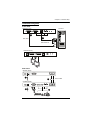
ATEN CE604 is a DVI Dual View KVM Extender that allows you to control two computers from a single console (keyboard, mouse, and monitor) up to 50m away. It supports high-definition video resolutions up to 1920 x 1200 @ 60Hz, ensuring stunning visual quality. The extender features front panel pushbuttons for easy port selection and status monitoring, and a built-in RS-232 port for connecting peripherals like barcode scanners or serial printers.
ATEN CE604 is a DVI Dual View KVM Extender that allows you to control two computers from a single console (keyboard, mouse, and monitor) up to 50m away. It supports high-definition video resolutions up to 1920 x 1200 @ 60Hz, ensuring stunning visual quality. The extender features front panel pushbuttons for easy port selection and status monitoring, and a built-in RS-232 port for connecting peripherals like barcode scanners or serial printers.


-
 1
1
-
 2
2
-
 3
3
-
 4
4
-
 5
5
-
 6
6
-
 7
7
-
 8
8
-
 9
9
-
 10
10
-
 11
11
-
 12
12
-
 13
13
-
 14
14
-
 15
15
-
 16
16
-
 17
17
-
 18
18
-
 19
19
-
 20
20
-
 21
21
-
 22
22
-
 23
23
-
 24
24
-
 25
25
-
 26
26
-
 27
27
-
 28
28
-
 29
29
-
 30
30
-
 31
31
-
 32
32
-
 33
33
-
 34
34
-
 35
35
-
 36
36
-
 37
37
-
 38
38
-
 39
39
-
 40
40
-
 41
41
-
 42
42
-
 43
43


ATEN CE604 is a DVI Dual View KVM Extender that allows you to control two computers from a single console (keyboard, mouse, and monitor) up to 50m away. It supports high-definition video resolutions up to 1920 x 1200 @ 60Hz, ensuring stunning visual quality. The extender features front panel pushbuttons for easy port selection and status monitoring, and a built-in RS-232 port for connecting peripherals like barcode scanners or serial printers.
Ask a question and I''ll find the answer in the document
Finding information in a document is now easier with AI
Related papers

Other documents
-
iogear GCE616U User manual
-
Newstar NS560UTP User manual
-
ATEN Technology CE-300 User manual
-
Black Box ACS1009A User manual
-
Fisher & Paykel CE302 Series User guide
-
-
Grace Spacebar User manual
-
 Grace Design spacebar stereo User manual
-
-
 Alto-Shaam HSM-24/5S User manual

