Page is loading ...

1
Contents
© 1994, 1995 by Motorola, Inc., Radio Products Group
8000 W. Sunrise Blvd., Ft. Lauderdale, FL 33322
Printed in U.S.A. 04/95. All Rights Reserved.
, Motorola, JT 1000, Private-Line, Digital Private-Line, PAC•RT, Quik-Call II,
Channel Scan, Touch-Code, and Single Tone are trademarks of Motorola, Inc.
Introduction
Inspection and Unpacking............................................................................1
Warnings, Cautions, and Notes ...................................................................1
Getting Started
Antennas..................................................................................................2
Battery Installation.....................................................................................3
Battery Removal........................................................................................3
Belt Clip Installation and Removal (on Nickel-Cadmium Batteries Only) ................4
Universal Connector Seal Removal................................................................6
Controls, Switches, Indicators, and Connectors..............................................6
Keypad.....................................................................................................7
Display.....................................................................................................7
Display Light .............................................................................................7
Status Annunciators...................................................................................8
Basic Radio Operation
Radio On/Off, Power-Up .............................................................................9
Selective Channel Display and HOME Key.......................................................9
Monitoring..............................................................................................10
Receiving a Transmission..........................................................................10
Transmitting............................................................................................11
Low-Battery Alert.....................................................................................11
Radio Operation with Features
General..................................................................................................12
Coded Squelch Operation ..........................................................................12
Variable RF Power ...................................................................................12
Programmable Features ...........................................................................12
Channel Scan
TM
Features...........................................................................16
Quik-Call II
TM
Decode Signalling....................................................................20
Touch-Code
TM
, Dual-Tone Multi-frequency (DTMF)...........................................21
Repeater Talkaround ................................................................................22
Smart PTT..............................................................................................22
Time-Out Timer........................................................................................23
PAC•RT
TM
...............................................................................................23
Receive-Only Channel................................................................................23
Single Tone
TM
Signalling .............................................................................23
Batteries and Accessories
Battery Information..................................................................................24
Recharging Nickel-Cadmium Batteries.........................................................24
Charging Temperature..............................................................................24
Short Circuit ...........................................................................................24
Memory Effect (Reduced Charge Capacity)...................................................24
Battery Disposal......................................................................................25
Nickel-Cadmium Battery Recycling Facilities..................................................26
Accessories List......................................................................................27

Contents (cont.)
MAEPF-
MAEPF-
MAEPF-
MAEPF-
MAEPF-
MAEPF-
MAEPF-
MAEPF-
2
General Information
Transmitting Distance...............................................................................29
Radio Care .............................................................................................30
Safety Standards .....................................................................................31
Restrictions ............................................................................................32
Service...................................................................................................33
Express Service Plus (ESP), U.S.A. only.......................................................34
Product Service Information ......................................................................35
Parts Information.....................................................................................35
Computer Software Copyrights ..................................................................36
Patent Disclosure ....................................................................................36

1
1 Introduction
Welcome to the Motorola JT 1000 Portable Radio. JT 1000 radios are
sophisticated, state-of-the-art communication units, with models available in VHF
and UHF frequency ranges, with up to 16 user-programmable channels.
Pioneering the latest technology in radio electronics, Motorola JT 1000 radios
provide features that were once only available in more expensive radios. Intelligent
and flexible software increases the radio’s capability, decreases the radio's
physical size, and permits many of the radio's features to be customized for your
specific needs.
Inspection and Unpacking
Inspect the shipping carton for any signs of damage. Remove and check the
contents to be sure that all ordered items have been shipped. If items have been
damaged during transit, report the damage to the shipping company immediately.
An operational procedure, practice, or condition, etc., which may
result in injury or death if not carefully observed.
!
WARNING
An operational procedure, practice, or condition, etc., which may
result in damage to the equipment if not carefully observed.
!
Warnings, Cautions, and Notes
Throughout this publication, you will notice the use of WARNINGS,
CAUTIONS, and Notes. These notations are used to emphasize that safety
hazards exist, and care must be taken or observed.
CAUTION
Note: An operational procedure, practice, or condition, etc., which is
important to emphasize.
JT 1000
HOME
2
ABC
1
3
DEF
6
MNO
5
JKL
4
GHI
7
PRS
8
TUV
9
WXY
0
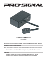
Radio Packing Box Contents:
• Radio
• Antenna
• Nickel-Cadmium Battery
• Belt Clip (with Nickel-
Cadmium Battery Only)
• Help Card (with some
shipments)
• Radio Information Sheet
• Operating Instructions
Manual
• Universal Connector
Seal

VHF
Wide Band
Helical
VHF
Helical
UHF
Helical
UHF
Wide Band
Whip
EDITO
R
EH
JW
B
2 Getting Started
2
Antennas
Radio/Antenna Identification
An information label is attached
to the back of your radio (chassis),
just under the battery contacts. A
radio model number is identified on
this label. A typical model number
might be H01KDH9PA3AN. The
fourth position of the model number
(in this case “K”) identifies the
Radio Operating-Frequency Chart
Fourth-Position Frequency
Character Band
K 136 - 178 MHz
R 403 - 470 MHz
S 450 - 512 MHz
Antennas are frequency sensitive and are color coded according to the
frequency range of the antenna. The color code indicator is the insulator in the
center of the base of the antenna. The following illustrations and chart will help
identify the antenna, antenna frequency range, and corresponding color code.
Refer to the Radio Operating-Frequency Chart and the Antenna Identification
Chart on this page to ensure that the match between your radio and antenna is
correct.
Antenna Installation
Screw the threaded end of the antenna into the antenna receptacle located on
top of the radio. Rotate the antenna clockwise until it fits firmly against the bushing.
Antenna Approx. Insulator Frequency Antenna
Type Length Color Code Range Kit No.
In. MM
VHF Wide Band 8.1 203 RED 136-178MHz NAD6563
Helical
VHF 7.8 195 YELLOW 136-151MHz NAD6566
Helical 7.3 183 BLACK 151-162MHz NAD6567
6.9 172 BLUE 162-178MHz NAD6568
UHF Wide Band 5.2 130 GREY 403-520MHz NAE6549
Whip
UHF 3.3 83 RED 403-435MHz NAE6546
Helical 3.2 80 GREEN 435-470MHz NAE6547
3.2 79 BLACK 470-520MHz NAE6548
Antenna Identification Chart
operating frequency band of the radio. The Radio Operating-Frequency Chart lists all
fourth-position alpha characters and corresponding frequency band.

4 Getting Started (cont.)
Belt Clip Installation and Removal
(on Nickel-Cadmium Batteries Only)
Installing the Belt Clip
1. Insert a pencil or equivalent size
instrument between the inside of the belt
clip and the metal clip assembly to hold
the metal clip partially sprung (metal clip
should be approximately parallel with the
plastic portion of the belt clip).
2. Align the metal tabs of the belt clip with
the plastic slots of the battery housing.
3. Slide the belt clip onto the battery,
pushing firmly until you hear a click.
4. Remove the pencil from the clip.
Removing the Belt Clip
1. Insert a pencil or equivalent size
instrument between the inside of the belt
clip and the metal clip assembly to hold
the metal clip partially sprung (metal clip
should be approximately parallel with the
plastic portion of the belt clip).
2. Push the flat blade of a #2 slotted
screwdriver (or like instrument) between
the battery housing and the belt clip
release tab.
3. While performing step 2, slide the belt
clip out and away from the battery, and
remove the screwdriver.
4. Remove the pencil from the clip.
3 Getting Started (cont.)
Battery Installation
1. Turn off the radio and hold it with the
back of the radio facing up.
2. Place the two tabs of the battery
(located at the inside base of the
battery) into the metal cutouts of the
radio (located at the inside base of the
radio).
3. Rotate the battery toward the radio and press
the top of the battery into the radio until both
battery release levers “click” into place.
Note: The battery is shipped uncharged. Batteries
must be charged before use. (See Battery Information
section.)
Battery Removal
1. Turn off the radio and hold it such that the battery side
of the radio is tilted down.
2. Press down on the two battery release levers.
3. With release levers pulled down, the top of the
battery will fall away from the radio.
4. Remove the battery from the radio.
MAEPF 22056 A
MAEPF-22057-B
MAEPF 22058 B
!
CAUTION
Installation and removal of the belt
clip assembly should be done with
the battery removed from the radio
or damage could be done to the
radio housing.
!
CAUTION
The disposable, non-rechargeable
alkaline battery (NTN7319) can be
used with the JT 1000 Model Only.

6 Getting Started (cont.)
5 Getting Started (cont.)
Figure 1.
Controls, Switches,
Indicators, and
Connectors
JT 1000
4 three-position
(ABC) toggle switch
5 indicator LED
6 orange top button
2 channel selector
1 on/off/volume control
13 universal
connector
7 side button 1
8 side button 2
9 side button 3
10 push-to-talk
(PTT) switch
12 microphone
14 noise-
cancelling
port
A
B
C
11 display
3 two-position concentric switch
1
3
5
7
13
15
9
11
HOME
2
ABC
1
3
DEF
6
MNO
5
JKL
4
GHI
7
PRS
8
TUV
9
WXY
0
15 keypad
Feature
3-Position Toggle
Top
Side Button
2-Position Keypad
ABC
Button
123
Concentric Menu
Carrier Squelch X* X*
Change Squelch Setting X
DTMF Access/Exit X*
Keypad Lock X*
Light X X X
Mode-Slaved Squelch X*
Monitor X X X*
Mon/Scan Program Status X X X
Multiple Select PL X*
PAC•RT X X X
Repeat/Talkaround X X X
Single Tone Encode X X X
Scan On/Off X X X X X X
Scan/Program Status X X X
Scan/Scan Program X X X X X
Sel/Program/Number–Edit X*
Variable RF Power X X X X
Table 1. Switch, Button, and Keypad Programming
Note: * = Feature is programmed at shipment to this switch or button.
X = Feature can be programmed to this switch or button.
If the universal connector seal is attached to
the radio:
1. Turn the radio off when removing the
seal.
2. Grasp the radio as illustrated, and push
your thumb against the tabbed portion of
the seal with enough force to unsnap the
universal connector seal from the radio.
3. Rotate the seal around the antenna to
move it away from the universal
connector; slide the seal off of the
antenna and completely away from the
radio.
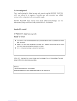
Controls, Switches, Indicators, and Connectors
(Refer to Table 1/Figure 1 for Switch and Button Programming Information)
1 On/Off/Volume Control – Turns the radio on and off, and adjusts the volume
level.
2 Channel Selector – Selects the operating channel (1-16).
3 Two-Position Concentric Switch ( ) - Keypad Lock, orange button (DTMF),
and Multiple Select PL lock/unlock.
4 3-Position Toggle Switch (A B C) – RSS programmable. User selects feature.
5 LED Indicator – Indicates the radio operating status; green/red light-emitting
diode (LED).
6 Orange Top Button – DTMF mode enable/disable.
7 Side Button 1 (Blue/Teal) – Radio Service Software programmable, serves as
a program/edit button.
8 Side Button 2 – Radio Service Software programmable, and inputs Multiple
select PL.
9 Side Button 3 – Radio Service Software programmable, default from factory is
monitor.
10 Push-To-Talk (PTT) Switch – Engages the transmitter and puts the radio in the
transmit mode.
11 Display – Provides visual information to the user.
12 Microphone Port – Accepts voice input to the radio’s microphone.
13 Universal Connector – Provides access for Radio Service Software
programming and side-connector programming key, testing, and accessory
connections.
14 Noise-Cancelling Port – Reduces background noise during transmit.
15 Keypad – Provides control and data interface.
Universal Connector Seal Removal
When not in use, keep the side connector covered using the
universal connector seal provided.
Touching the top two contacts of the universal connector when
transmitting could result in a radio frequency burn.
!
WARNING
Universal
Connector
Seal
Push
Off

7
7 Getting Started (cont.)
HOME
2
ABC
1
3
DEF
6
MNO
5
JKL
4
GHI
7
PRS
8
TUV
9
WXY
0
Keypad
The radio includes a 15-button keypad that
activates or inputs data. The keypad’s upper 12 keys
are arranged, and function, like a standard telephone
keypad. In addition, the keypad’s top three keys access
menu selections. The keypad’s bottom three keys are
the left arrow key, HOME key, and right arrow key. The
left and right arrow keys are used to enter the
Programming Features mode.
The left arrow key is
also used for editing when you are entering information
manually from the keypad when in program mode.
Pressing the left arrow key will backspace and erase the
display, one character at a time.
Display
The radio has a 14-character, one-line liquid crystal display (LCD), which
displays either alphanumeric messages or feature-selection information. Above
the character displays are status annunciators that indicate some of the radio’s
operating conditions.
Display Light
If poor light conditions make the display difficult to read, turn on the radio’s
display backlight by pressing the HOME button. The light will remain on for a
preprogrammed time period before it turns off automatically. If, while the light is
on, any key or button is pressed (except for the PTT switch), any knob is turned
(except for On/Off volume control), or any toggle switch is moved, the light will
remain on for an additional time period.

8 Getting Started (cont.)
MAEPF-
MAEPF-
MAEPF-
MAEPF-
MAEPF-
MAEPF-
MAEPF-
MAEPF-
8
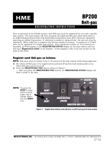
Status Annunciators
The status annunciators indicate the status of the following radio functions:
• Battery Status ( ) – Indicates the state of the radio’s battery. Flashes
when the battery is low.
• Coded Squelch ( ) – Indicates the type of receive squelch that is in
effect for the active conventional channel; ON = CARRIER SQUELCH;
OFF = CODED SQUELCH.
• Call Received ( ) – Flashes when a Quik-Call II page is received.
• Scan ( ) – Indicates when the radio is scanning; ON = SCANNING;
OFF = NOT SCANNING.
• Priority Scan ( ) – The presence of a dot along with the scan annunciator
indicates the scanning of a priority mode; FLASHING DOT = PRIORITY
• Programming Mode ( ) – A flashing annunciator box Indicates that the
radio is in the programming mode; FLASHING = IN PROGRAMMING MODE;
OFF = NOT IN PROGRAMMING MODE.
• Keypad Lock ( ) – Disables the keypad, orange top button (DTMF), and
Side Button 2 (Multiple Select PL). The annunciator does not flash.
• Direct ( ) – Indicates whether you are talking directly to another radio
(talkaround), or through a repeater; ON = DIRECT; OFF = REPEATER.
LCD and Status Annunciators

MAEPF-
MAEPF-
MAEPF-
MAEPF-
MAEPF-
MAEPF-
MAEPF-
MAEPF-
9
9 Basic Radio Operation
Radio On/Off, Power-Up
Turn the radio on by rotating the on/off/volume
control 1/4-turn clockwise. The LED on top of the radio
will light green, and a SELF TEST screen will appear on
the LCD to indicate that the radio is performing a self
test. A high-pitched tone (Radio Service Software
programmable) is generated to indicate that the radio
has passed the self test. If a low-pitched tone, screen
display FAIL 01/82, or any combination of the two
occurs (indicating a malfunction), turn the radio off,
check the battery, and turn the radio back on.
Note: The power-up self test verifies the
operational status of the microprocessor-based
systems but does not check all of the radio
frequency components and does not check the
operation of all customer specific features.
Motorola recommends that the functionality of the
radio be periodically checked by an authorized
Motorola service shop.
Selective Channel Display and HOME Key
After power-up, a selective channel display is
shown. This display is a per radio feature programmed
by Radio Service Software one of two ways:
• one way, the dispatch display, shows the channel
number (selected by the channel selector) and a
number that represents the squelch code assigned
to that receive channel. If the PTT is pressed while
viewing the dispatch display, the display will not
change.
• the other way, the numeric display, shows the
receive frequency of the channel (selected by the
channel selector) and the squelch type or squelch
code assigned to that receive frequency. If the PTT
is pressed while viewing the numeric display, the
display will change to show the transmit frequency
and the transmit squelch type or squelch code.
When in the programming mode, if no keys are
pressed in 15 seconds (Radio Service Software
programmable), the radio will automatically exit that
mode and return to the selective channel display.
The HOME key is used to exit the current menu
screen and return to the previous menu screen. If the
existing menu allowed data entry and side button 1 was
not pressed, pressing the HOME key will cause that data
to be lost.
On/Off
Volume Control
Do not remove the battery from the radio
during power-up or during any programming
sequence. This could corrupt codeplug data.
!
CAUTION
OR

10 Basic Radio Operation (cont.)
MAEPF-
MAEPF-
MAEPF-
MAEPF-
MAEPF-
MAEPF-
MAEPF-
MAEPF-
10
PTT
side
button 3
side
button 2
Monitoring
Turn the radio on, momentarily press side button 3
(default setting from factory), and listen for channel activity.
To place the radio in the permanent, forced-monitor mode,
press and hold side button 3 for approximately five seconds
(time programmable via Radio Service Software). The radio
emits a brief high-pitched tone as it enters the forced-
monitor mode. To return the radio to its original squelch
state, one of the following can be done: press side button 3
again (silent-monitor mode on carrier squelch channels),
press the PTT, change channels, or turn the radio off and
on.
Receiving a Transmission
1. Turn the radio on and set the channel selector to the
desired channel position.
2. Listen for a transmission and adjust the volume control
to a comfortable listening level. If no transmission is
heard, press the monitor button to unsquelch the
radio, and adjust the background noise to a
comfortable listening level.
Note: The squelch level is a per-channel setting that
can be reprogrammed using the keypad. Refer to Radio
Operation with Features section, Front Panel
Programming,
Adjust Squelch
for details.
3. Your radio is now set to receive transmissions on the
selected frequency.
4. Refer to Radio Operation with Features section, Coded
Squelch Operation paragraph for Tone Private-Line
®
(PL) and Digital Private-Line™ (DPL) operation.
Notes:
• If the channel selector control is placed on an
unprogrammed channel (blank channel), an error
tone is emitted until the channel selector control is
rotated to a programmed (valid) channel.
• The LED will blink red in the receive mode to
indicate that the channel is busy.

MAEPF-
MAEPF-
MAEPF-
MAEPF-
MAEPF-
MAEPF-
MAEPF-
MAEPF-
11
11 Basic Radio Operation (cont.)
Transmitting
1. Turn the radio on and set the channel selector
to the desired channel position.
2. Listen for a transmission and adjust the
volume control to a comfortable listening level.
If no transmission is heard, press side button
3 to unsquelch the radio, and adjust the
background noise to a comfortable listening
level.
3. Do not interrupt another user. If the channel
on which you are transmitting is programmed
for coded squelch operation, ensure that the
channel is not in use by momentarily
depressing the monitor button to listen for
activity, or check for the LED to be flashing
red.
4. To transmit, hold the radio in a vertical
position with the microphone two to three
inches away from the lips. When the channel
is clear, press and hold the PTT on the side of
the radio and speak slowly and clearly into the
microphone area. The LED will be red while in
the transmit mode. When your transmission is
completed, release the PTT to listen.
Note: Avoid blocking the noise-cancelling port
while transmitting to take full advantage of the
noise-cancelling feature.
Low-Battery Alert
While in transmit mode, the LED will blink red
if the battery falls below a low voltage level (Radio
Service Software programmable, blinking LED is
factory default). The radio can be programmed via
Radio Service Software to emit a double-chirp tone
to indicate a low-battery condition. If a low-battery
condition exists, the tone will be emitted when the
PTT is released in transmit mode, and when the
low-battery condition is detected in receive mode.
Also, in the transmit and receive modes, when
a low-voltage level is detected, the LCD battery-
status annunciator will blink.
Note: If the JT 1000 radio is using an NTN7319
Alkaline battery pack, the low-battery alert point is
automatically reconfigured.
1
3
5
7
13
15
9
11
A
B
C
LED, red
Control Top
Low-Battery
Annunciator Display
13
15
1
3
5
7
9
11
Channel Selector

12 Radio Operation with Features
MAEPF-
MAEPF-
MAEPF-
MAEPF-
MAEPF-
MAEPF-
MAEPF-
MAEPF-
12
General
All discussions of radio features assume specific combinations of the 3-
position toggle switch, side button programming, and radio model capability.
Your particular radio operation may vary depending on these choices.
Coded Squelch Operation
Tone Private-Line (PL), Digital Private-Line (DPL), and carrier squelch
operation are all available in the same radio, on a per-channel basis. When
operating in carrier squelch mode, all traffic on that channel is heard. When
operating PL or DPL, your radio hears those messages intended for you. When
this feature is channel-slaved, PL, DPL, or carrier squelch is programmed to
each transmit and receive frequency, and you need not move any switches for
activation. Alternatively, this feature can be programmed to the 3-position
toggle switch. See Table 2 toward the rear of this manual.
Variable RF Power
Transmit power on JT 1000 radios is programmed on a per channel
basis, one or more channels (as required) for high power and other channels
for low power. Programming of this feature can be done by:
• the user, via the keypad and display (see page 15), or by
• Radio Service Software.
Note: Unless programmed otherwise by Radio Service Software, JT 1000
radios will transmit low power only when using an alkaline battery.
Programmable Features
The JT 1000 Radio uses the display and keypad to give you quick access
to the following features, programmable per channel:
• multi-selectable PL/DPL/CSQ,
• squelch level adjust, and
• power selection.
Important Note: While programming any one of these features, all transmit
and receive functions are disabled.
Once the radio is turned on and the HOME display
is shown, pressing either the left ( ) or the right
arrow key ( ) prompts the radio to show two softkey
features (SQL and PWR) on the 14-character display,
with key-like outlines, known as “softkeys,” to make them look like keys.
Selecting the SQL or PWR feature is accomplished by pressing the softkey
button directly below it. The softkey buttons ( , , ) are the top row of
keys on the keypad. The left key controls the left feature and the middle key
controls the middle feature. For detailed information, refer to “Adjust Squelch
(SQL)” and “Select Power (PWR”) paragraphs on page 15.
3
DEF
2
ABC
1

MAEPF-
MAEPF-
MAEPF-
MAEPF-
MAEPF-
MAEPF-
MAEPF-
MAEPF-
13
13 Radio Operation with Features
SQUELCH = 4
LOW POWER
(1 - 8)
OR
QUIT ?
PRESS HOME
LCD Display/Menu Screen Tree

MAEPF-
MAEPF-
MAEPF-
MAEPF-
MAEPF-
MAEPF-
MAEPF-
MAEPF-
14
14 Radio Operation
with Features (cont.)
• Multi-Selectable PL/DPL/CSQ Mode
A numeric-display screen and a dispatch-
display screen,(see Basic Radio Operation
section) apply to Multi-Selectable
PL/DPL/CSQ Mode. For the description of
Multi-Selectable PL/DPL/CSQ Mode, the
dispatch-display screens are used.
Turn the radio on and select a channel, for
example channel 3. The screen will display the
channel number and the squelch code
assigned to that channel (CH 3 3). The
squelch code is for both transmit and receive.
Press side-button 2; the display will show the
channel number, indicate the type of squelch,
and display the DPL code or PL frequency if
applicable. For example (CH 3 = #131). The #
sign signifies DPL squelch. Use the arrow keys
to scroll through and select any of the other
channel codes to be moved to the channel
that you are on. For example, while scrolling,
the screen would display: CH 3 = C4, CH 3 =
C5, CH 3 = C6, etc. Stop on the desired
channel code (for example CH 3 = C5) and
press side button 2 again to move channel 5’s
squelch code to channel 3. Channel 5’s code
will remain on channel 3 even if the radio is
turned off and back on. To return to original
channel programming, press the key
followed by the key within two seconds.
This function is enabled from the factory, but
can be disabled by Radio Service Software.
Note: Multi-Selectable channel programming
can be cleared (reset) on the selected channel
by pressing the HOME key while in the Multi-
Selectable PL/DPL/CSQ Mode.
• Program Edit Mode
Turn the radio on and select a channel. The
LCD shows the channel number and the
squelch code assignment. To enter the
program edit mode, press either one of the
arrow keys on the keypad. The SQL PWR
softkey menu screen will be displayed. When
in this menu, pressing the key changes the
display to QUIT?, which lasts for two seconds.
The screen changes to display YES NO.
Press softkey button to return to radio
operation. Press softkey button and return
to the SQL PWR softkey menu.
Note: Programming/editing will be only for
the channel selected.
HOME
HOME
0
1
3
DEF

MAEPF-
MAEPF-
MAEPF-
MAEPF-
MAEPF-
MAEPF-
MAEPF-
MAEPF-
15
Adjust Squelch
(SQL) - Press softkey button
. The display will show the current
squelch setting on the selected channel for two
seconds (for example SQUELCH = 4). The screen
will prompt for a new setting. Enter new setting (1-
8), 4 nominal, and press the top side (blue/teal,
edit) button. Choose setting 1 for loose squelch, 8
for tight squelch. The display returns to the
SQL PWR menu screen. Repeat for each channel
as applicable.
Select Power
(PWR) - Press softkey button
. The display will show the current
power selection for two seconds (for example
LOW POWER). The screen will prompt for a new
selection (LOW HIGH). Press the softkey under
the desired power setting if a power setting change
is desired. The display returns to the SQL PWR
menu screen.
15 Radio Operation
with Features (cont.)
1
2
ABC

MAEPF-
MAEPF-
MAEPF-
MAEPF-
MAEPF-
MAEPF-
MAEPF-
MAEPF-
16
16 Radio Operation
with Features (cont.)
Channel Scan™ Features
A. Description
The scan feature allows the user to monitor activity on different channels.
The radio is capable of scanning up to 16 channels in the scan list, with one list
available per radio. A radio can be programmed via Radio Service Software for
either non-priority or priority channel scan with PL/DPL or carrier squelch
operation.
Notes:
• A radio programmed for non-priority channel scan, will not have priority-
channel capability.
• With scan on, the menu system and the DTMF feature are both
non-functional.
Non-priority channel scan means no scan channel has priority over another.
The scanner stops on the first scan channel with activity. When activity is over
and the “hang time” has expired, scan proceeds to the next active channel. Hang
time is the amount of time that the radio user has to respond to a received
transmission. Hang time is programmable on a per-radio basis.
Priority channel scan means that any one of the radio's scan channels may
be designated as a priority channel. The priority channel is checked for activity
more frequently than non-priority channels. If the radio is locked on a non-priority
channel and activity is detected on the priority channel, the radio will leave the
non-priority channel and lock onto the priority channel. An alert tone is generated
to indicate that a priority message is being received.
Note: With scan on, the channel selected automatically becomes a member
of the scan list.
Three types of scan are available:
1. Automatic Scanning (Auto Scan) – is preprogrammed in the radio using
Radio Service Software, and slaved to one or more channels. A radio with
auto scan will automatically begin scanning whenever the auto scan channel
position is selected. When auto scan is programmed to a channel, that
channel will always operate in the scan mode. The number of auto-scan
channels is equal to one less than the number of channels in the radio.
2. Preprogrammed Conventional Channel Scan – is preprogrammed in the
radio using Radio Service Software.
3. Operator-Selectable Conventional Channel Scan - lets the user program the
scan list by using a combination of side buttons or toggle switch, and the
channel selector knob. The programming procedure is explained, in detail, in
paragraphs titled “Programming Operator-Selectable Channel Scan.”
Transmitting (pressing the PTT) while in the scan mode is accomplished in
one of three ways (programmed via Radio Service Software):
• Revert to Selected Mode – lets you transmit while scanning is in
progress. The transmission will occur on the channel selected by the
channel selector.

MAEPF-
MAEPF-
MAEPF-
MAEPF-
MAEPF-
MAEPF-
MAEPF-
MAEPF-
17
17 Radio Operation
with Features (cont.)
Channel Scan
TM
Features (cont.)
• Talk-Back Scan – lets the user respond on the channel with activity
within a specified “hang-time”. Hang time is the amount of time that the
radio user has to respond to a received transmission. If the user misses
the allotted time and tries to transmit, transmission occurs on the
channel currently selected by the channel selector.
• Designated Tx Channel – transmission will always occur on this channel,
whether or not there is activity on a scan channel.
B. Operation
How to Turn Channel Scan On
Turn the radio on and place the radio in the scan-on mode (for units with
preprogrammed and/or operator-selectable channel scan), or rotate the channel
selector and stop on the preprogrammed scan channel (for units with auto scan).
Scanning begins.
During scan, the display shows the channel that the rotary knob is set on.
When activity is detected on a channel, the radio locks onto it, monitors the
conversation, and the display shows the active scan channel. When activity is
over and the “hang time” (programmable) has expired, the scanner proceeds to
the next active channel.
Scan Annunciators
When scan is turned on, the scan status
annunciator on the display turns on, and remains on
until scan is turned off. If scanning stops on a priority
channel, the priority scan status annunciator (dot) will
be flashing.
How to Turn Channel Scan Off
Place the 3-position switch in the scan off position
or press the scan off button (for units with
preprogrammed and/or operator-selectable channel
scan), or rotate the channel selector to any position
other than a channel with channel scan (for units with
auto scan). Scanning stops.
How to Delete a Nuisance Channel from the Scan
List
While in channel scan operation, if conversation on
a particular non-priority channel (nuisance channel)
bothers you, temporarily delete that channel from the
scan list by pressing side button 1 when the radio is
locked onto the channel. The channel will be temporarily
deleted from the list until scan is turned off. The
channel is put back into the list upon re-entry into scan.
The channel is also put back into the scan list if you
change modes by rotating the channel selector. All
scan list channels except one, may be nuisance
deleted. The priority channel may not be nuisance
deleted.
side
button 1

MAEPF-
MAEPF-
MAEPF-
MAEPF-
MAEPF-
MAEPF-
MAEPF-
MAEPF-
18
18 Radio Operation
with Features (cont.)
1
3
5
7
13
15
9
11
A
B
C
LED, red
Channel Scan
TM
Features (cont.)
Programming “Operator-Selectable
Channel Scan”
1. Enter the scan programming mode in
one of two ways, programmed by Radio
Service Software:
• by placing the 3-position toggle switch
in the scan program position, or
• by selecting the proper side button.
An alert tone will sound and the display will
show SCAN PROGRAM.
Note: The SCAN PROGRAM display is shown
for the duration of scan programming. The
display does not indicate scan programming
status. Scan programming status is indicated
by the LED.
2A. Add a non-priority scan channel to the
scan list by rotating the channel selector
to the desired channel to be added, and
press the select button. The LED will
illuminate green to indicate that the
channel is now in the scan list. Add
another non-priority scan channel to the
scan list by rotating the channel selector
to the next channel to be added. Press
the select button to enter the channel as
a non-priority channel, and again the LED
will illuminate green to indicate that the
channel is in the scan list. A total of 16
non-priority channels can be entered into
the scan list in this manner.
2B. Add a priority scan channel to the scan
list by rotating the channel selector to
the desired channel.
If the selected channel is already in the
scan list (LED illuminated green),
pressing the select button again makes
that channel the priority channel. The
LED will change from green to red.
If the selected channel is not already in
the scan list (LED off), add it by pressing
the select button. The LED will
illuminate.green. Press the select button
again to select this channel as the
priority channel. The LED will change
from green to red.
1
3
5
7
13
15
9
11
A
B
C
LED, green

MAEPF-
MAEPF-
MAEPF-
MAEPF-
MAEPF-
MAEPF-
MAEPF-
MAEPF-
19
19 Radio Operation
with Features (cont.)
Channel Scan
TM
Features (cont.)
3. Change the priority scan channel in the same manner as you would add
a priority scan channel. When any scan channel is made the priority
channel, the previous priority channel automatically becomes a non-
priority channel.
4A. Delete a non-priority scan channel from the scan list as follows:
• Ensure that the radio is in the scan program mode.
• Rotate the channel selector to the channel you want to delete. The
LED should be green, indicating that the channel selected is in the
scan list.
• Press the select button twice to delete the channel from the list. On
the first press, the LED will illuminate red and on the second press,
the LED will go off.
4B. Delete the priority scan channel from the scan list by rotating the
channel selector to the priority channel (LED illuminated red). Press the
select button. The channel will be deleted from the scan list, and the
LED will go off. Add the channel back to the scan list as a non-priority
scan channel by pressing the select button again (LED will illuminate
green).
5. Exit the scan programming mode in one of two ways:
• If scan is Radio Service Software programmed to the 3-position
switch, place the switch in the off position, thus selecting another
radio function, or
• If scan is Radio Service Software programmed to a side button, press
the button again.
A tone is generated and SCAN PROGRAM is removed from the display
to indicate that scan programming has been exited.

MAEPF-
MAEPF-
MAEPF-
MAEPF-
MAEPF-
MAEPF-
MAEPF-
MAEPF-
20
Quik-Call II™ Decode Signalling
A. Description
Quik-Call II decode is a convenient way for a
dispatcher to voice page an individual or group. Quik-
Call II decode also eliminates the need for you to
listen to traffic that is of no concern. This feature is
enabled on a per-channel basis, and available as
individual call, group call, or dual call.
B. Operation
To turn on and operate Quik-Call ll:
1. Turn the radio on.
2. Activate Quik-Call II by placing the 3-position
toggle switch in the (A) position (if so
programmed), or by rotating the channel
selector to the desired channel with Quik-Call ll
programmed. The display will show QC.
3. When a page is received, the LED flashes green,
the call-received annunciator flashes, and an
interrupted alert tone (individual call) or
continuous alert tone (group call) is heard. A
voice message will follow. The LED will continue
to flash for the entire length of the message.
4. Return the radio to the Quik-Call II paging mode
by pressing the monitor button. If the monitor
button is not pressed, the radio will “auto-reset”.
The Quik-Call II feature is factory programmed
for auto-reset. When carrier is detected, the
automatic reset timer is stopped; when carrier
is lost, the auto-reset timer is started over.
Notes:
• Quik-Call II auto-reset is cancelled when the
monitor button is pressed or when the
channel is changed. The auto-reset timer is
started over if it was running when a Quik-Call
II was decoded, or when a successful
transmission was initiated.
• Quik-Call II will be decoded and an alert
generated regardless of the PL or DPL
squelch configuration on that channel.
A
B
C
20 Radio Operation
with Features (cont.)
/