Page is loading ...

D00951 Revision C
Electrostatic Discharge Simulator
ETS PinPulse™ Model 9910
Operating Manual

D00951 Revision C - Page 2
3101 Mt Carmel Ave. Glenside, PA
│
833
-
ESD
-
GURU (833
-
373
-
4878)
Table of Contents
I. IMPORTANT SAFETY INFORMATION AND INSTRUCTIONS ......................... 3
II. Description of Components ................................................................................ 5
III. Set-Up Guide ................................................................................................... 7
IV. Quick Start Guide ............................................................................................. 8
V. Operating Instructions ..................................................................................... 10
A. Waveform Verification Procedures ................................................................. 10
B. Device Testing ............................................................................................... 10
C. Testing Hints .................................................................................................. 15
VI. Calibration, Maintenance, Troubleshooting ................................................... 16
VII. Warranty ....................................................................................................... 16
Appendix A - ESD Testing Background ............................................................. 17
Appendix B - Model 9910 components - Detailed description ............................ 21
Appendix C - Waveform Verification – Detailed Procedures .............................. 27

D00951 Revision C - Page 3
3101 Mt Carmel Ave. Glenside, PA
│
833
-
ESD
-
GURU (833
-
373
-
4878)
I. IMPORTANT SAFETY INFORMATION AND INSTRUCTIONS
The equipment described in this Manual is designed and manufactured to operate according to
defined procedures and within defined design limits. Any misuse may result in electric shock, fire,
injury, or damage. For safe operation, the following rules must be observed for installation, use,
and maintenance. Read the following safety instructions before operating the instrument.
POWER
POWER CORD: Use only the power cord specified for this equipment and certified for the
country of use. If the power (mains) plug is replaced, follow the wiring connections specified
for the country of use. When installing or removing the power plug hold the plug, not the
cord.
The power cord provided is equipped with a 3-prong grounded plug (a plug with a third
grounding pin). This is both a safety feature to avoid electrical shock and a requirement for
correct equipment operation. If the outlet to be used does not accommodate the 3-prong plug,
either change the outlet or use a grounding adapter.
FUSES: The Model 9910 utilizes switching power supplies that operate over the voltage range
of 90-260VAC, 50/60Hz. This unit incorporates resettable fuses. To reset, the instrument must
be powered down for 10 seconds before turning the power back on.
POWER LINE VOLTAGE (MAINS): If the line (mains) voltage is changed or isolated by an
autotransformer the common terminal must be connected to the ground (earth) terminal of the
power source.
OPERATION CAUTION!
THE MODEL 9910 DISCHARGE SIMULATOR IS CAPABLE OF PRODUCING HIGH
VOLTAGE OUTPUT PULSES UP TO 8,250 VOLTS AT A STORED ENERGY LEVEL OF
ABOUT 75x10
-4
JOULES. WHEN IT IS NECESSARY TO HANDLE THE DUT OR ANY OF
THE OUTPUT INTERCONNECT TEST LEADS, IT IS RECOMMENDED THAT THE HIGH
VOLTAGE ON/OFF SWITCH BE PLACED IN THE OFF POSITION. THIS IS INDICATED BY
“VOLTAGE OFF” BEING DISPLAYED AND THE RED LED ABOVE THE HV ON/OFF
BUTTON TURNED OFF.

D00951 Revision C - Page 4
3101 Mt Carmel Ave. Glenside, PA
│
833
-
ESD
-
GURU (833
-
373
-
4878)
DO NOT TOUCH OR COME IN CONTACT WITH THE EQUIPMENT WHILE IN USE. Voltages used in the
equipment may cause serious discomfort, injury, or death. ESD testing, by definition, involves hazardous
voltage and unenclosed wiring. Power down and discharge all circuitry before contact.
DO NOT OPERATE WITH COVERS OR PANELS REMOVED. Voltages inside the equipment may pose a
further threat of serious discomfort, injury, or death.
DO NOT OPERATE IN THE PRESENCE OF A PACEMAKER OR OTHER MEDICAL OR LIFE-
SUSTAINING ELECTRONICS. The equipment produces high-voltage discharges which may cause
malfunction of nearby electronic circuits.
DO NOT OPERATE WITH SUSPECTED EQUIPMENT FAILURES. If any odor or smoke becomes apparent
turn off the equipment and unplug it immediately. Failure to do so may result in electrical shock, fire,
explosion, or permanent damage to the equipment. Contact the factory for maintenance instructions.
DO NOT OPERATE IN AN EXPLOSIVE ATMOSPHERE: Operating the equipment in the presence of
flammable gases or fumes constitutes a definite safety hazard and may cause explosion or fire. For
equipment designed to operate in such environments the proper safety devices must be used such as dry
air or inert gas purge, intrinsically safe barriers and/or explosion-proof enclosures.
DO NOT USE IN ANY MANNER NOT SPECIFIED OR APPROVED BY THE MANUFACTURER:
Unapproved use may result in damage to the equipment or present an electrical shock or
fire hazard.

D00951 Revision C - Page 5
3101 Mt Carmel Ave. Glenside, PA
│
833
-
ESD
-
GURU (833
-
373
-
4878)
II. Description of Components
For a detailed description of all components, see Appendix B.
Included in the standard Model 9910 package are the following:
Item
Qty.
Description
Model 9910 PinPulse system
1 Main control unit. See Figure 2.1
9910 DUT board holder 1 DUT board holder, 30 degree. See Figure 2.1
9910 40-pin DIP DUT adapter 1 PC board with 40-pin ZIF socket. See Figure 2.1
9910 Universal DUT holder 1 PC board with clamp to secure DUT. See Figure 2.2
Programming Pins 50 Gold plated, Red insulated, .025 x 0.30”. See Figure 2.3.
9910 Output Cable Set 1 Set of 6 “e-z hook” cables with ferrite cores. See Figures 2.1 and 2.3.
Cable, RS232 1 DB9F-DB9F, 6 ft. length
Cable, AC line 1 USA standard, 6 ft. length, 18 AWG, black
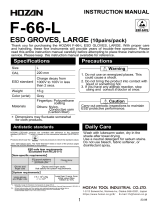
The Model 9910 Electrostatic Discharge Simulator, shown in Figure 2.1, is designed to produce
discharge pulses that meet the requirements of the respective HBM, MM and HMM standards to
perform required ESD sensitivity testing.
Figure 2.1. Model 9910 PinPulse ESD Simulator
Atop the 9910 enclosure is the ergonomically-designed 30⁰ DUT board holder. This fixture accommodates
the 40-pin DIP adapter or the Universal DUT holder.
Mode
l 9910
40
-
pin DIP
Adapter
DUT board
holder

D00951 Revision C - Page 6
3101 Mt Carmel Ave. Glenside, PA
│
833
-
ESD
-
GURU (833
-
373
-
4878)
The Universal DUT Holder secures the device under test so test leads can be connected directly to the
appropriate pin pair.
Figure 2.2. Universal DUT Holder
A set of 50 programming plugs is provided for the DUT mounting boards.
Figure 2.3. Programming Pins.
A set of dedicated color-coded cables, is included to provide waveforms that meet the specified
HBM, HMM and MM requirements.
HBM HMM MM
Figure 2.3. Output cables

D00951 Revision C - Page 7
3101 Mt Carmel Ave. Glenside, PA
│
833
-
ESD
-
GURU (833
-
373
-
4878)
III. Set-Up Guide
Step 1 – Connect the HV cables to 9910
For HBM testing, select the Red/Black HV cable
pair and plug the color-coded banana plugs into
the 9910 output panel jacks marked “HBM” and
“GND”.
Step 2 – Connect the power cable to 9910
With the front panel power switch OFF, Connect
the 3-pin power plug into the connector located
on the rear panel.

D00951 Revision C - Page 8
3101 Mt Carmel Ave. Glenside, PA
│
833
-
ESD
-
GURU (833
-
373
-
4878)
IV. Quick Start Guide
Step 1 – Verify Setup
Ensure the AC cable is connected, the HV test
cables are plugged in, and the front panel
power switch is OFF. Place the
“Computer/Keypad” switch in the Keypad
position. This switch selection is applied when
power is switched ON, and has no effect at
other times
Step 2 - Turn On Power
Switch the unit ON using the front panel
switch. When the system is initially turned on,
it reads the “Computer / Keypad” switch and
defaults to the HBM MANual mode with
Voltage OFF and the system in the Charge
mode.
Step 3 – Select Voltage
Depress the V PROG or Program Voltage button
and key in the desired voltage.
Press the ENTer key.
The selected voltage will be displayed and the
red LED next to the V ON/OFF button will turn
on.
To turn the voltage OFF, depress the V ON/OFF
(3) button. Press the key again to turn the
voltage back ON.
To change polarity, depress the V +/- (2) button.
HV LED

D00951 Revision C - Page 9
3101 Mt Carmel Ave. Glenside, PA
│
833
-
ESD
-
GURU (833
-
373
-
4878)
Step 4 - Initiate a Discharge
When the voltage is turned on, the storage
capacitor becomes charged.
To initiate a discharge, depress the DISCHG
key. In the MANual mode a single discharge
will occur with each keystroke. (In the AUTO
mode, depressing the DISCHG key will
initiate the discharge/interval sequence
programmed.) Each discharge will be
counted on the display.

D00951 Revision C - Page 10
3101 Mt Carmel Ave. Glenside, PA
│
833
-
ESD
-
GURU (833
-
373
-
4878)
V. Operating Instructions
A. Waveform Verification Procedures
See Appendix C for the detailed procedures for Waveform Verification.
Human Body Model (HBM) – Mil-Std 883E, Method 3015.8, ANSI/ESD/JEDEC JS-001-2010
(formerly ANSI/ESD-STM5.1 & JESD A114B). SEE SECTION C.1
These test methods require system calibration utilizing the discharge pulse current waveform. The
Human Body Model is C=100pF and R=1500 Ohms.
Machine Model (MM) – ANSI/ESD-STM5.2, JEDEC 22-A11C. SEE SECTION C.2
These standards require system calibration utilizing the discharge pulse waveform obtained from a
200pF capacitor discharged through 0 Ohms to ground. The same oscilloscope and current transducer
setup used for HBM verification are used for the MM verification waveforms.
Human Metal Model (HMM) - IEC 61000-4-2. SEE SECTION C.3
This international standard is primarily used for evaluating the ESD susceptibility of electronic
equipment, and more recently to evaluate the electronic devices themselves. The 150pF/330 contact
model simulates a charged person holding a tool such as a screwdriver discharging to an electronic
component or system. The discharge waveform shown in Figure 5.0-10 are the requirements specified
for contact discharge.
B. Device Testing
Place the system in Keypad Mode:
In keypad mode, the ESD Simulator is controlled by the 16-button keypad shown in Figure 5.1
keypad. (To enter keypad mode, switch the front panel power switch OFF, set the rear panel toggle
switch to keypad, and switch power ON.)
Figure 5.1: Keypad

D00951 Revision C - Page 11
3101 Mt Carmel Ave. Glenside, PA
│
833
-
ESD
-
GURU (833
-
373
-
4878)
Turn On the Power
When the system is initially turned on, it defaults to the HBM MANual discharge mode with Voltage
OFF and the system in the Charge mode.
Figure 5.2. Power up display.
Select the Testing Model
To select HBM testing, depress the HBM (4) key, then ENTer. Make sure that the HBM
cable set (RED & BLACK) is used and are plugged into the HBM output jack on the
Output panel. Otherwise, incorrect waveforms will be obtained. This test is limited to
8250V.
To select MM testing, depress the MM (5) key, then ENTer. Make sure that the MM cable
set (YELLOW & GREEN) is used and are plugged into the MM output jack on the
Output panel. Otherwise, a incorrect waveforms will be obtained. This test is limited to
1000V.
To select HMM testing, depress the HMM (6) key, then ENTer. Make sure that the HMM
cable set (BLUE & ORANGE) is used and are plugged into the HMM output jack on
the Output panel. Otherwise, a incorrect waveforms will be obtained. This test is limited
to 4250V.
(CDM Testing is an Optional mode, used with the ETS Model 9903 CDM Test Fixture).
To select CDM testing the Model 9903 Charge Device Model Test Fixture must be used
and the 9910 configured for this test. Depress the CDM (6) key then ENTer. This test
is limited to 1000V.
Select the Voltage
Depress the PROG V button and key in the desired voltage. The maximum voltage
will be determined by the discharge Model selected.
Press the ENTer key.
The selected voltage will be displayed and the red LED next to the V ON/OFF button
will turn on.

D00951 Revision C - Page 12
3101 Mt Carmel Ave. Glenside, PA
│
833
-
ESD
-
GURU (833
-
373
-
4878)
To turn the voltage OFF, depress the V ON/OFF (3) key. Press the key again to turn
the voltage back ON.
To change polarity, depress the V +/- (2) button.
Preset Voltages
The voltage automatically turns on when the PRESET V and a preset key from 1-9 is selected.
To turn off the voltage depress the V ON/OFF (3) key. Press the key again to turn the voltage
back on.
The preset voltages are initially set at the factory as follows:
Key Preset Voltage Verification V Model
1 100 MM
2 200 MM
3 400 MM
4 800 MM
5 500 HBM, HMM
6 1000 HBM, HMM
7 2000 HBM, HMM
8 4000 HBM, HMM
9 8000 HBM
To change the preset voltage, proceed as follows:
Depress the PROG V button and key in the desired voltage.
Depress the PRESET V then press and hold the desired preset location (key 1-9) for
approximately 5 sec.
Release the key to save the selected voltage.
To select a preset voltage, depress the PRESET V (1-9) key to select the desired preset
voltage (keys 1-9).
Initiating a Discharge – Manual Mode
When the voltage is turned on the storage capacitor becomes charged.
To initiate a discharge depress the DISCHG key. In the MANual mode a single discharge will
occur with each keystroke. Each discharge will be counted on the display.
Auto Mode
To select the AUTO mode, depress the AUTO/MAN (1) key. The display will show that the AUTO mode
has been selected and defaults to 3 discharges at 1 second interval.
If another sequence is desired, depress the AUTO MODE SETTING key. The display will ask “Number
of discharges”. Key in any number from 1-9 then press ENTer.

D00951 Revision C - Page 13
3101 Mt Carmel Ave. Glenside, PA
│
833
-
ESD
-
GURU (833
-
373
-
4878)
The display will then ask for “Interval”. This is the time in seconds between discharges. Key in the
desired number from 1-99 seconds then press ENTer.
The display will look similar to the example shown in Figure 3.0-2.
At the end of a discharge sequence, the last discharge will be displayed that corresponds to the
number of discharges selected.
To stop the AUTO mode sequence, depress the CLR button. The display will show “Stop at x”.
Error Correction: To correct an entry, depress the CLR button. To clear an entire function, depress
and hold the CLR button for approximately 5 seconds. The system returns to the default settings.
Initiating a Discharge – Auto Mode
When the voltage is turned on the storage capacitor becomes charged.
To initiate a discharge depress the DISCHG key. In the AUTO mode, depressing the DISCHG key
will initiate the discharge/interval sequence programmed. Each discharge will be counted on the
display.
Computer Control (User Programming Guide)
The Model 9910 with computer control capability has an embedded microcontroller that is currently
capable of RS232 serial communication. In order to fully control ETS equipment using this link, the user
MUST select the COMPUTER mode using the KEYBOARD/COMPUTER toggle switch located on the
rear panel and then cycle the power. The main POWER switch cannot be controlled automatically. The
user MUST turn the unit on and off manually.
RS232 parameters
Baud rate 9600 1 stop bit
8 data bits no flow control
even parity Communication cable: NULL cable (pin 2 to 3; pin 3 to 2)
Character codes:
1. Start code, control-B, ascii STX, hex 02, which is abbreviated below as * . This character is used to
start all messages to ETS devices.
2. : (colon). This is the delimiter character used to separate the parts of a command.
3. Command Code, an abbreviation for the function requested, XXX (three upper case characters). This
denotes a particular command or operation. The 3-character code is created from the description of
the command for ease of memorization. For example: SHB is the abbreviation for the command
SetHumanBodymodel to select HBM testing.
4. , (comma). A delimiter character used only between a command and its argument.
5. value (integer number). This number is the desired numeric value for the entered command.

D00951 Revision C - Page 14
3101 Mt Carmel Ave. Glenside, PA
│
833
-
ESD
-
GURU (833
-
373
-
4878)
6. End code, control-I, ascii TAB, hex 09, which is abbreviated below as HT. This is the horizontal tab
character typed as CTRL-I on a standard computer keyboard. This is a non-printing control character
that is used to end all messages to ETS equipment.
Command Structure:
There are two types of commands.
Function Command Parameter Command
*:XXX:HT *:XXX,value:HT
Parameter commands must be followed by a comma and an argument.
For example: SVP must have a number (such as 10, 2000, etc.), the requested voltage.
Any valid command received by the 9910 will create the reply “String received. Wait for
execution.” An invalid command will receive a “?” reply.
For commands starting with S (abbreviation for “Set…”), a valid command will receive a “done”
return message after it is executed successfully. An invalid command will receive a “?” return
message.
For a command starting with G (abbreviation for “Get…”), the return message will be the value
that end user is looking for. An invalid command will receive a “?” return message.
Replies from the 9910 end with [CR][LF]. (Hex [0D][0A], keyboard [CTRL-M][CTRL-J])
List of Commands:
Command name Syntax 9910 1
st
Reply 9910 Finished reply
SetVoltageNegative: *:SVN,value:HT String received. Wait for execution. done
SetVoltagePositive: *:SVP,value:HT String received. Wait for execution. done
SetHumanBodymodel: *:SHB:HT String received. Wait for execution. done
SetHumanMetalmodel: *:SHM:HT String received. Wait for execution. done
SetMachineModel: *:SMM:HT String received. Wait for execution. done
SetDisCharge: *:SDC:HT String received. Wait for execution. done
GetVolTage: *:GVT:HT String received. Wait for execution. XXXX
GetModeL: *:GML:HT String received. Wait for execution. HBM/HMM/MM
A special command implements the IEEE identification scheme:
Identify Command: *IDN HT String received. Wait for execution. ETS,9910,<software version>

D00951 Revision C - Page 15
3101 Mt Carmel Ave. Glenside, PA
│
833
-
ESD
-
GURU (833
-
373
-
4878)
Examples:
1. To set voltage to +1000V, send string [*:SVP,1000:HT]
2. To set voltage to -1000V, send string [*:SVN,1000:HT]
3. To select HBM, send string [*:SHB:HT]
4. To select HMM, send string [*:SHM:HT]
5. To select MM, send string [*:SMM:HT]
6. To discharge, send string [*:SDC:HT]
7. To get current voltage setting, send string [*:GVT:HT]
8. To get current model, send string [*:GML:HT]
Notes:
Any valid command string will receive the reply “String received. Wait for execution.”
An invalid string will receive a ”?” almost immediately.
After task is completed, the reply “done” is sent by the 9910.
If using Hyper Terminal, type ^I for the tab character.
It can take up to 5 seconds to switch polarities.
C. Testing Hints
Testing requirements are often specified in terms of levels. The recommended stress levels are slightly
different between the JEDEC and ANSI/ESD specifications as listed in the table below.
Level
JESD Level V
ANSI/ESD Level V
1
100
125
2
200
250
3
500
500
4
1000
1000
5
2000
1500
6
-
2000

D00951 Revision C - Page 16
3101 Mt Carmel Ave. Glenside, PA
│
833
-
ESD
-
GURU (833
-
373
-
4878)
VI. Calibration, Maintenance, Troubleshooting
The Model 9910 Electrostatic Discharge Simulator, like all precision electronic instruments,
should be returned to the factory once a year for calibration.
There is no user maintenance or adjustment required. Always handle the HV output
connection cables with care. If the instrument needs to be moved, provide padding and
protection to avoid applying any shock to the unit.
If a waveform problem is found, re-check that the HV output cables are securely plugged
into the correct receptacles and the clips are clean and making proper contact with the test
fixture.
If using the Keypad/Computer switch, remember to power cycle the unit after setting the
switch.
If the 9910 reports difficulty in charging to a voltage, contact the factory for assistance.
VII. Warranty
Limited Warranties. Seller warrants that all goods manufactured and delivered
hereunder shall (a) conform to any samples, drawings, specifications or other
written documents provided to Seller by Buyer, or approved by Buyer to Seller
and (b) be free from all defects in workmanship and material. Buyer’s sole
remedy against Seller for breach of either of the specifically mentioned warranty
shall be the repair or replacement, at Seller’s sole option, of the defective
workmanship or material. Seller expressly disclaims all other warranties, express
and/or implied, including but not limited to those of merchantability and fitness for
a particular purpose. In no event shall Seller be liable, under either warranty or
otherwise, to Buyer in excess of the purchase price of the products paid to Seller
by Buyer. In no event shall Seller be liable for any loss or damage arising directly
or indirectly from the use of the product or for consequential or incidental
damages. Seller’s specified warranties will expire and lapse (i) for renewable
items (such as gloves, iris ports and desiccants), sixty (60) days from date of
shipment and (ii) for all standard equipment and otherwise nonrenewable items,
one year from date of shipment.

D00951 Revision C - Page 17
3101 Mt Carmel Ave. Glenside, PA
│
833
-
ESD
-
GURU (833
-
373
-
4878)
Appendix A - ESD Testing Background
The rapid advancement in the electronics industry during recent decades has placed increasing
importance on the understanding of electrostatics and its effect on electronic devices and systems.
Electrostatic discharge (ESD) is a common cause of microelectronic circuit failure. Many devices can be
seriously damaged or destroyed by an electrostatic discharge below 20 Volts. The sensitivity to ESD of
other components has also become evident through use, testing and failure analysis. The trend in
technology towards greater complexity and increased packaging density, hence thinner dielectrics
between active elements results in parts becoming ever more sensitive to ESD.
Failure mechanisms of electrical and electronic parts due to ESD typically include thermal breakdown,
metallization melt and bulk breakdown that are power dependent; dielectric breakdown, metallization to
metallization arc over, surface breakdown and surface inversion that are voltage dependent.
ESD can also induce latent failure mechanisms in both MOS structures and bipolar junctions in both
discrete devices and microcircuits. This latent failure mechanism results in performance degradation and
eventually a failure.
Personnel are prime sources of ESD for damaging electrical and electronic parts. Electrostatic charges
generated by rubbing or separating materials are readily transmitted to a person’s conductive sweat layer
charging that person. When a person handles or comes in close proximity to an ESD sensitive part, that
part can then be damaged from a direct discharge by touching the part or by subjecting the part to an
electrostatic field. The ESD from a human body can be reasonably simulated for test purposes from the
circuit shown in Figure A.1.
Figure A.1: Basic Human Body Model equivalent circuit

D00951 Revision C - Page 18
3101 Mt Carmel Ave. Glenside, PA
│
833
-
ESD
-
GURU (833
-
373
-
4878)
This circuit is specified in Mil-Std-883H, Method 3015.8 and ANSI/ESDA/JEDEC JS-001-2010
(formally ANSI/ESD-STM 5.1 and JEDEC TEST METHOD A114.A) to represent a human body
discharge for ESD testing. The human body capacitance may be as high as several hundred
picofarads, but more typically, ranges between 60 to 500pF. Studies have shown that
approximately 80% of the population that was tested has a capacitance of 100pF or less. The
variation in human capacitance is due to factors such as the amount and type of clothing and
footwear worn by personnel and differences in floor materials.
Human body resistances can range from 100 to 100,000 Ohms, but is typically between 500
and 5,000 Ohms for actions that are considered pertinent to holding or touching ESD sensitive
parts or containers of ESD sensitive parts. The variation in human body resistance is due to
factors such as the amount of moisture, salt and oils at the surface, contact area and pressure
of the skin. A value of 1,500 Ohms provides a reasonable lower human body resistance value.
In view of the above, Mil-Std-883H specifies a Human Body Model (HBM) using 100pF
discharged through 1,500 Ohms.
For power sensitive parts, a change to a worst case Human Body Model capacitance (i.e.,
greater than 100pF) could result in damage to ESD sensitive parts at voltage levels below
those shown in Mil-Std-883H, Appendix 1. Therefore, a component that has been classified as
non-ESD sensitive could actually become ESD sensitive under more stringent Human Body
Model conditions. For voltage sensitive ESD parts, a variation in the capacitance value in the
test circuit generally will not affect ESD sensitivity. However, a decrease in Human Body Model
resistance will increase the voltage and power delivered to the part that could adversely affect
voltage and power sensitive ESD sensitive parts at lower HBM voltage levels. The Human
Body Model specified is considered a reasonable test circuit for evaluating the sensitivity of
ESD sensitive parts because personnel are generally the most common source of damaging
ESD.
The Model 9910 Electrostatic Discharge Simulator is an instrument specifically designed to
simulate the electrostatic discharge produced by human handling and meets all of the testing
requirements specified in Mil-Std-883H, Method 3015.8, ANSI/ESDA/JEDEC JS-001-2010,
and other specifications based on the Mil-Std-883H model.
The Machine Model (MM) as defined in ANSI/ESD-STM 5.2 and JEDEC 22-A11C is “An
electrostatic discharge simulation test based on a discharge network consisting of a charged
200 picofarad capacitor and (nominally) 0 (zero) Ohms of series resistance. Actual series
resistance and inductance are specified in terms of the current waveform through a shorting
wire. The simulation test approximates the electrostatic discharge from a machine.” The Machine
Model network is standard with the Model 9910.
Another model commonly used is the Hand/Tool model also referred to as the Human Metal
Model (HMM) that is specified in IEC 61000-4-2. This model simulates a person holding a tool
when discharging to a device. It is typically used for system ESD testing, but is now also being

D00951 Revision C - Page 19
3101 Mt Carmel Ave. Glenside, PA
│
833
-
ESD
-
GURU (833
-
373
-
4878)
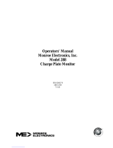
used to evaluate components and devices. The standard model is 150pF/330, but other
models such as 150pF/150 and 150pf/2000 are also specified. The Model 9910 incorporates
the 150pF/330 model as standard. The other models are available as options.
Human Body Model (HBM) Machine Model (MM) Human Metal Model (HMM)
(100pF/1,500) (200pF/0) (150pF/330)
Figure A.2: Typical HBM, MM and HMM waveforms
However, another type of discharge that is far more severe than the discharge from a person
touching a device is the Charge Device Model (CDM). This occurs when the device itself
becomes charged then touches ground resulting in a very fast rise time discharge.
The Charged Device Model (CDM) as defined in ANSI/ESD-STM 5.3, JEDS22-C101C and
AEC-Q101-005 is when a component is slowly charged to a given voltage and then discharged
to ground through one or more leads of the device. The Model 9903 Charge Device Model
Test Fixture that connects to the Model 9910 is available as an option.
Figure A.3: Basic Charge Device Model equivalent circuit
Charge
DUT
Touch to
GND for
discharge
GND

D00951 Revision C - Page 20
3101 Mt Carmel Ave. Glenside, PA
│
833
-
ESD
-
GURU (833
-
373
-
4878)
Available as an optional accessory, the Model 9902 Remote Discharge Probe shown in
Figure A.4 can be used as a handheld device or with the addition of remote cables, be
attached to an automatic test system. The Probe operates only in the LO Range (up to
1000V) for the HBM and MM models.
Figure A.4: ETS Model 9902 Remote Discharge Probe
/